MPLS over ATM: VC Merge
Available Languages
Contents
Introduction
This document provides a sample configuration of Multiprotocol Label Switching (MPLS) over ATM using Virtual Circuit (VC) merge.
Prerequisites
Requirements
Before you attempt this configuration, ensure that you have a basic understanding of ATM, MPLS, and Open Shortest Path First (OSPF).
Components Used
Use one of these routers in order to implement this configuration:
-
Edge Label Switch Router (LSR)—Any ATM router that runs Cisco IOS® Software Release 12.0 or later, with MPLS features. This configuration uses Cisco 3600 series routers that run Cisco IOS Software Release 12.1(3)T and a Cisco 7200 router that runs Cisco IOS Software Release 12.0(8)S.
-
ATM LSR—Any ATM switch such as the LightStream 1010 or Catalyst 85xx MSR. Cisco recommends that you use software version WA4.8d or later. The LightStream 1010 requires a Feature Card PerFlow Queueing (FC-PFQ).
You can find a more precise description of the supported platforms in Designing MPLS for ATM.
The information in this document was created from the devices in a specific lab environment. All of the devices used in this document started with a cleared (default) configuration. If your network is live, make sure that you understand the potential impact of any command.
Conventions
For more information on document conventions, refer to the Cisco Technical Tips Conventions.
Refer to these links for more information on MPLS configuration and conventions:
-
The VC merge facility is standardized in the Internet Engineering Task Force (IETF) Multiprotocol Label Switching Architecture and MPLS using Label Distribution Protocol (LDP) and ATM VC Switching documents. You can access both of these documents from the IETF MPLS Charter
 .
. -
You can find configuration instructions in the MPLS over ATM documentation.
-
The dimensioning of the number of VCs used in an MPLS network is covered in the Dimensioning MPLS Label VC Space section of Designing MPLS for ATM.
Background Information
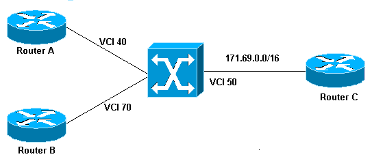
The VC merge facility allows a switch to aggregate multiple incoming flows with the same destination address into a single outgoing flow. Wherever VC merge occurs, several incoming labels are mapped to one single outgoing label. Cells from different Virtual Channel Identifiers (VCIs) that go to the same destination are transmitted to the same outgoing VC with the use of multipoint-to-point connections. This sharing of labels reduces the total number of VCs required for label switching. Without VC merge, each path (with the same Ingress router and same Forwarding Equivalent Class (FEC)) consumes one label VC on each interface along the path. VC merge reduces the label space shortage by sharing labels for different flows with the same destination, that is, the same FEC.
This figure shows an example of VC merge. In this figure, Routers A and B send traffic to prefix 171.69.0.0/16 on Router C. The ATM switch in the middle is configured with a single outbound VCI 50 bound to prefix 171.69.0.0/16. Data flows from Routers A and B congregate in the ATM switch and share the same outgoing VC. Cells that come from VCI 40 and VCI 70 are buffered in the input queues of the ATM switch until complete AAL5 frames are received. The complete frame then is forwarded to Router C on VCI 50.

Configure
In this section, you are presented with the information to configure the features described in this document.
Note: To find additional information on the commands used in this document, use the Command Lookup Tool (registered customers only) .
Network Diagram
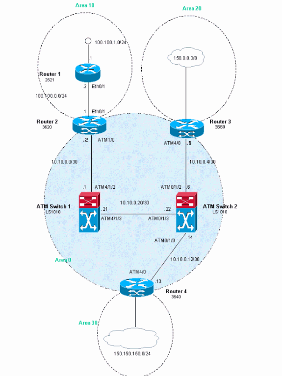
This document uses this network setup.

Configurations
In this example, ATM Virtual Path Identifiers (VPIs) 2, 3, or 4 are used. But, it is not mandatory to specify which Virtual Paths (VPs) are used for MPLS.
Configure the IP Cisco Express Forwarding (CEF) on the routers. If you use a Cisco 7500 router, you must ensure that the ip cef distributed command is enabled.
This document uses these configurations.
| Router 1 |
|---|
! interface Loopback0 ip address 223.0.0.12 255.255.255.255 ! interface Loopback1 ip address 100.100.1.1 255.255.255.0 ! interface FastEthernet0/1 ip address 100.100.0.2 255.255.255.0 duplex auto speed auto ! router ospf 1 network 100.100.0.0 0.0.0.255 area 10 network 100.100.1.0 0.0.0.255 area 10 network 223.0.0.12 0.0.0.0 area 10 ! |
| Router 2 |
|---|
! ip cef ! interface Loopback0 ip address 223.0.0.11 255.255.255.255 ! interface Ethernet0/1 ip address 100.100.0.1 255.255.255.0 ! interface ATM1/0 no ip address no atm scrambling cell-payload no atm ilmi-keepalive ! interface ATM1/0.1 label-switching ip address 10.0.0.2 255.255.255.252 label-switching atm vpi 2-4 label-switching ip ! router ospf 1 network 10.0.0.0 0.0.0.255 area 0 network 100.100.0.0 0.0.0.255 area 10 network 223.0.0.11 0.0.0.0 area 0 ! |
| Router 3 |
|---|
! ip cef ! interface Loopback0 ip address 223.0.0.21 255.255.255.255 ! interface Loopback1 ip address 200.200.0.1 255.255.255.255 ! interface ATM4/0 no ip address no atm scrambling cell-payload no atm ilmi-keepalive pvc qsaal 0/5 qsaal ! pvc ilmi 0/16 ilmi ! ! interface ATM4/0.1 label-switching ip address 10.0.0.6 255.255.255.252 label-switching atm vpi 2-4 label-switching ip ! router ospf 1 redistribute static network 10.0.0.0 0.0.0.255 area 0 network 200.200.0.0 0.0.0.255 area 20 network 223.0.0.21 0.0.0.0 area 0 ! ip route 158.0.0.0 255.0.0.0 Null0 ! |
| Router 4 |
|---|
! ip cef ! interface Loopback0 ip address 223.0.0.3 255.255.255.255 no ip directed-broadcast ! interface Loopback1 ip address 150.150.1.1 255.255.255.0 no ip directed-broadcast ! interface ATM4/0 no ip address no ip directed-broadcast no ip mroute-cache no atm ilmi-keepalive ! interface ATM4/0.1 label-switching ip address 10.0.0.13 255.255.255.252 no ip directed-broadcast label-switching atm vpi 2-4 label-switching ip ! router ospf 1 network 10.0.0.0 0.0.0.255 area 0 network 150.150.0.0 0.0.255.255 area 30 network 223.0.0.3 0.0.0.0 area 0 ! ip route 150.150.150.0 255.255.255.0 Null0 ! |
| ATM Switch 1 |
|---|
! interface Loopback0 ip address 223.0.0.1 255.255.255.255 no ip directed-broadcast ! interface ATM4/1/2 ip address 10.0.0.1 255.255.255.252 no ip directed-broadcast no ip route-cache cef no atm ilmi-keepalive label-switching atm vpi 2-4 label-switching ip ! interface ATM4/1/3 ip address 10.0.0.21 255.255.255.252 no ip directed-broadcast no ip route-cache cef no atm ilmi-keepalive label-switching atm vpi 2-4 label-switching ip ! router ospf 1 network 10.0.0.0 0.0.0.255 area 0 network 223.0.0.1 0.0.0.0 area 0 ! |
| ATM Switch 2 |
|---|
! interface Loopback0 ip address 223.0.0.2 255.255.255.255 no ip directed-broadcast ! interface ATM0/1/0 ip address 10.0.0.14 255.255.255.252 no ip directed-broadcast no ip route-cache cef no atm ilmi-keepalive label-switching atm vpi 2-4 label-switching ip ! interface ATM0/1/2 ip address 10.0.0.5 255.255.255.252 no ip directed-broadcast no ip route-cache cef no atm ilmi-keepalive label-switching atm vpi 2-4 label-switching ip ! interface ATM0/1/3 ip address 10.0.0.22 255.255.255.252 no ip directed-broadcast no ip route-cache cef no atm ilmi-keepalive label-switching atm vpi 2-4 label-switching ip ! router ospf 1 network 10.0.0.0 0.0.0.255 area 0 network 223.0.0.2 0.0.0.0 area 0 ! |
Verify
This section provides information you can use in order to confirm that your configuration works properly.
Certain show commands are supported by the Output Interpreter Tool (registered customers only) , which allows you to view an analysis of show command output.
-
show tag-switching atm-tdp capability
-
show tag-switching atm-tdp bindings
-
show atm vc
Issue the show tag atm-tdp command in order to obtain information on VC merging. This output, generated by the show tag-switching atm-tdp capability command, shows that VC merging is enabled on these interfaces:
ATMswitch2#show tag-switching atm-tdp capability

               VPI           VCI           Alloc   Odd/Even VC Merge
ATM0/1/0       Range         Range         Scheme  Scheme   IN   OUT
  Negotiated   [2 - 4]       [33 - 1023]   UNIDIR           -    -
  Local        [2 - 4]       [33 - 16383]  UNIDIR           EN   EN
  Peer         [2 - 4]       [33 - 1023]   UNIDIR           -    -

               VPI           VCI           Alloc   Odd/Even VC Merge
ATM0/1/2       Range         Range         Scheme  Scheme   IN   OUT
  Negotiated   [2 - 4]       [33 - 1018]   UNIDIR           -    -
  Local        [2 - 4]       [33 - 16383]  UNIDIR           EN   EN
  Peer         [2 - 4]       [33 - 1018]   UNIDIR           -    -

               VPI           VCI           Alloc   Odd/Even VC Merge
ATM0/1/3       Range         Range         Scheme  Scheme   IN   OUT
  Negotiated   [2 - 4]       [33 - 16383]  UNIDIR           -    -
  Local        [2 - 4]       [33 - 16383]  UNIDIR           EN   EN
  Peer         [2 - 4]       [33 - 16383]  UNIDIR           -    -
You also can check the VC merge for one particular FEC – for example, 100.100.1.1/32 – as seen in this output:
ATMswitch2#show tag atm-tdp bindings
Destination: 100.100.1.1/32
    Transit ATM0/1/2 2/47 Active -> ATM0/1/3 2/52 Active
    Transit ATM0/1/0 2/47 Active -> ATM0/1/3 2/52 Active

ATMswitch2#show atm vc
Interface  VPI  VCI   Type   X-Interface     X-VPI X-VCI Encap  Status
ATM0/1/0    2    47   TVC(I) ATM0/1/3          2   52           UP
ATM0/1/2    2    47   TVC(I) ATM0/1/3          2   52           UP
ATM0/1/3    2    52   TVC(O) ATM0/1/2          2   47           UP
                             ATM0/1/0          2   47           UP
If VC merge does not work (or if it is disabled with the no tag-switching atm vc-merge command), you receive this command output:
ATMswitch2#show tag atm-tdp bindings
Destination: 100.100.1.1/32
    Transit ATM0/1/2 2/38 Active -> ATM0/1/3 2/35 Active
    Transit ATM0/1/0 2/43 Active -> ATM0/1/3 2/43 Active

ATMswitch2#show atm vc
Interface  VPI  VCI   Type   X-Interface     X-VPI X-VCI Encap  Status
ATM0/1/0   2    43    TVC(I) ATM0/1/3          2   43           UP
ATM0/1/2   2    38    TVC(I) ATM0/1/3          2   35           UP
ATM0/1/3   2    35    TVC(O) ATM0/1/2          2   38           UP
ATM0/1/3   2    43    TVC(O) ATM0/1/0          2   43           UP
You can see from this output that disabling the VC merge function leads to the system using many more VCs.
Troubleshoot
There is currently no specific troubleshooting information available for this configuration.
Related Information
Revision History
| Revision | Publish Date | Comments |
|---|---|---|
1.0 |
05-Jun-2005 |
Initial Release |
Contact Cisco
- Open a Support Case

- (Requires a Cisco Service Contract)
 Feedback