MPLS over VP Tunnels
Available Languages
Contents
Introduction
A service provider normally gives you one or more virtual path (VP) tunnels to connect your devices together instead of a point-to-point physical link. This document explains the steps necessary to configure Multiprotocol Label Switching (MPLS) when you use VP tunnels.
Prerequisites
Requirements
There are no specific requirements for this document.
Conventions
Refer to Cisco Technical Tips Conventions for more information on document conventions.
Configure
In this section, you are presented with the information to configure the features described in this document.
Note: Use the Command Lookup Tool (registered customers only) to find more information on the commands used in this document.
Network Diagram
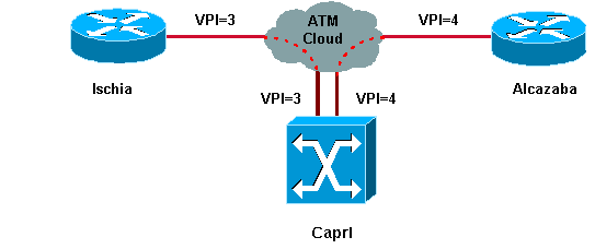
This document uses this network setup:

In this setup, the service provider has furnished two VP tunnels:
-
One between Ischia and Capri with VPI = 3 (virtual path identifier)
-
One between Alcazaba and Capri with VPI = 4
Ischia and Alcazaba are two Cisco 7200 routers that run Cisco IOS® Software Release 12.1(3a)E. Capri is a Catalyst 8540 Multiservice Switch Router (MSR) that runs release 12.0(10)W5(18c). Capri is a Tag Distribution Protocol (TDP) neighbor of Alcazaba and Ischia.
Note: You must run release 12.0(3)T or higher in order to configure this feature.
The configurations used here are for a Catalyst 8500 MSR, or LightStream 1010, and a router.
Configurations
This document uses these configurations:
| Ischia |
|---|
ip cef ! interface Loopback0 ip address 1.1.1.1 255.255.255.0 ! interface ATM2/0.3 tag-switching ip address 3.0.0.1 255.255.255.0 tag-switching atm vp-tunnel 3 tag-switching ip ! router ospf 6 log-adjacency-changes network 1.1.1.1 0.0.0.0 area 0 network 3.0.0.0 0.0.0.255 area 0 |
| Alcazaba |
|---|
ip cef ! interface Loopback0 ip address 2.2.2.2 255.255.255.0 ! interface ATM4/0.4 tag-switching ip address 4.0.0.1 255.255.255.0 tag-switching atm vp-tunnel 4 tag-switching ip ! router ospf 6 log-adjacency-changes network 2.2.2.2 0.0.0.0 area 0 network 4.0.0.0 0.0.0.255 area 0 |
| Capri |
|---|
interface ATM3/1/1 no ip address no ip directed-broadcast no ip mroute-cache no atm ilmi-keepalive atm pvp 3 atm pvp 4 ! interface ATM3/1/1.3 point-to-point ip address 3.0.0.2 255.255.255.0 no ip directed-broadcast no atm ilmi-keepalive tag-switching ip ! interface ATM3/1/1.4 point-to-point ip address 4.0.0.2 255.255.255.0 no ip directed-broadcast no atm ilmi-keepalive tag-switching ip |
Note: This configuration is similar to standard router configurations you can find here. The only difference is that you have to specify to the router that you use a VP tunnel. You can do this with the tag-switching atm vp-tunnel vpi command, where vpi is the VPI value that is associated with the tunnel that ends on this router.
Note: For the LightStream 1010 and Catalyst 8500 MSR, you need to configure one or more permanent virtual paths (PVPs) for each VP tunnel with the atm pvp vpi command. See here for a sample configuration. A subinterface is associated with each of these tunnels. For instance, the atm 3/1/1.3 interface is associated with PVP=3. You must configure this subinterface with tag-switching, as you do on the main interface.
Verify
Use these tag-switching show commands to test that your network operates properly:
-
show tag-switching tdp neighbor
-
show tag-switching atm-tdp bindings — This shows dynamic ATM tag information.
-
show tag-switching forwarding-table — This shows the Tag Forwarding Information Base (TFIB).
-
show tag-switching interfaces atm [int number] detail — This shows detailed tag switching information for each interface.
The Output Interpreter Tool (registered customers only) (OIT) supports certain show commands. Use the OIT to view an analysis of show command output.
This output is a result of these commands entered on the devices shown in the network diagram.
Ischia#show tag-switching tdp neighbor
Peer TDP Ident: 10.200.10.57:1; Local TDP Ident 1.1.1.1:1
        TCP connection: 3.0.0.2.11001 - 3.0.0.1.711
        State: Oper; PIEs sent/rcvd: 92/93; ; Downstream on demand
        Up time: 01:16:52
        TDP discovery sources:
          ATM2/0.3

Ischia#show tag-switching atm-tdp bindings
 Destination: 4.0.0.0/24
    Headend Router ATM2/0.3 (1 hop) 3/33  Active, VCD=127
 Destination: 1.1.1.0/24
    Tailend Router ATM2/0.3 3/33 Active, VCD=127
 Destination: 2.2.2.2/32
    Headend Router ATM2/0.3 (2 hops) 3/34  Active, VCD=128

Ischia#show tag-switching forwarding-table
Local  Outgoing    Prefix            Bytes tag  Outgoing   Next Hop
tag    tag or VC   or Tunnel Id      switched   interface
26     3/33        4.0.0.0/24        0          AT2/0.3    point2point
27     3/34        2.2.2.2/32        0          AT2/0.3    point2point

Ischia#show tag-switching interfaces detail
Interface ATM2/0.3:
        IP tagging enabled
        TSP Tunnel tagging not enabled
        Tagging operational
        Tagswitching turbo vector
        MTU = 4470
        ATM tagging:
                Tag VPI = 3 (VP Tunnel)
                Tag VCI range = 33 - 65535
                Control VC = 3/32

Capri#show tag-switching atm-tdp bindings
 Destination: 4.0.0.0/24
    Tailend Switch ATM3/1/1.3 3/33 Active -> Terminating Active
 Destination: 1.1.1.1/32
    Transit ATM3/1/1.4 4/33 Active -> ATM3/1/1.3 3/33 Active
 Destination: 3.0.0.0/24
    Tailend Switch ATM3/1/1.4 4/34 Active -> Terminating Active
 Destination: 2.2.2.2/32
    Transit ATM3/1/1.3 3/34 Active -> ATM3/1/1.4 4/33 Active

Capri#show tag-switching tdp neighbor
Peer TDP Ident: 1.1.1.1:1; Local TDP Ident 10.200.10.57:1
        TCP connection: 3.0.0.1.711 - 3.0.0.2.11001
        State: Oper; PIEs sent/rcvd: 95/94; ; Downstream on demand
        Up time: 01:18:49
        TDP discovery sources:
          ATM3/1/1.3
Peer TDP Ident: 2.2.2.2:1; Local TDP Ident 10.200.10.57:2
        TCP connection: 4.0.0.1.711 - 4.0.0.2.11002
        State: Oper; PIEs sent/rcvd: 93/95; ; Downstream on demand
        Up time: 01:18:22
        TDP discovery sources:
          ATM3/1/1.4

Capri#show tag-switching interfaces detail
Interface ATM3/1/1.3:
        IP tagging enabled
        TSP Tunnel tagging not enabled
        Tagging operational
        MTU = 4470
        ATM tagging: Tag VPI = 3, Control VC = 3/32
Interface ATM3/1/1.4:
        IP tagging enabled
        TSP Tunnel tagging not enabled
        Tagging operational
        MTU = 4470
        ATM tagging: Tag VPI = 4, Control VC = 4/32
This output is similar to standard tag-switching output, but one important difference is that it points to the VP tunnel interface.
Related Information
Revision History
| Revision | Publish Date | Comments |
|---|---|---|
1.0 |
20-Sep-2018 |
Initial Release |
Contact Cisco
- Open a Support Case

- (Requires a Cisco Service Contract)
 Feedback