Frequently Requested Information to Troubleshoot Optical Issues
Available Languages
Contents
Introduction
This document provides information that customers often request in order to effectively troubleshoot their network issues. The information that customers request can vary based on the severity of the issue.
Prerequisites
Requirements
There are no specific requirements for this document.
Components Used
This document is not restricted to specific software and hardware versions.
The information in this document was created from the devices in a specific lab environment. All of the devices used in this document started with a cleared (default) configuration. If your network is live, make sure that you understand the potential impact of any command.
Conventions
Refer to Cisco Technical Tips Conventions for more information on document conventions.
ONS 15454 Multi-service Provisioning Platforms (MSPP)
15454 Outage Data Collection
In order to troubleshoot an outage, you must collect the diagnostic files and list of failed circuits during the outage. You can collect the other items listed in this section after the outage clears.
Identify which circuits failed, and gather detailed information about the source and destination of each circuit. Select the Circuits tab and save the circuit list in the HTML format. Highlight the failed circuits. Save the file. The suggested file name is failed_circuits.html.
Collect detailed information on the source, destination and route on several of the failed circuits. Complete these steps:
-
Select one of the failed circuits from the Circuits list.
-
Click Edit.
-
Check the Show Detailed Map check box.
-
Use the PRINT SCRN key to capture the screen that displays the detailed circuit map.
-
Save the screen capture file as failed_curcuit_x.jpg, where x represents the number to identify the failed circuit.
-
Repeat Steps 1 through 5 for each failed circuit.
Figure 1 indicates the procedure to troubleshoot the issue.
Figure 1 – Flow Chart 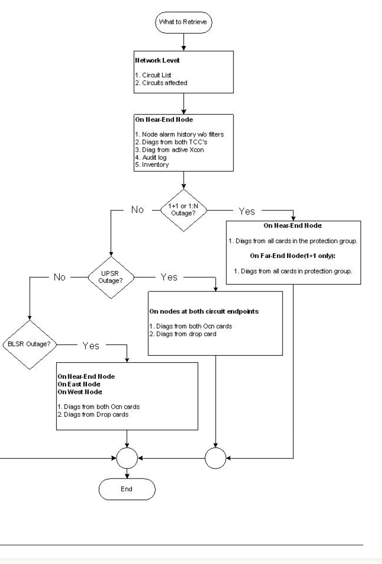
Tech-support.exe
Cisco TAC provides the Tech-support.exe utility.
Tech-support.exe is a command line utility that enables you to retrieve diagnostic information from Cisco ONS 15454/SONET, 15454/SDH and 15327 nodes. You can retrieve diagnostics or debug information from any card that is plugged into the node. The Tech-support.exe utility eliminates the need to manually establish a telnet connection to the card and type the commands. Tech-support.exe requires IP connectivity between the node and the PC, either directly or through a GNE. Close any active telnet session to the node before you run this utility.
In an ENE/GNE scenario, if the nodes run 3.XX software, you must disable the firewall on ENEs for the script to work.
The format to run Tech-support.exe is:
tech-support.exe --user "username" --pass "password" --all IP address nodename_diagnostic.cms
Note: Replace username, password, and IP address with the user name, password and IP address that you use.
Note: Here is a description of the parameters:
-
--user "username"
This parameter is optional unless you have secured SUPERUSER access with a non-standard user name. This option is only applicable to versions 2.3.3, 3.2.1 and later for ONS 15454 and 3.30 and later for ONS 15327. The default username applies to all other versions. Username must be double-quoted.
-
--pass "password"
This parameter is optional unless you have secured SUPERUSER access with a password. This option is only applicable to versions 2.3.3, 3.2.1 and later for ONS 15454, and 3.30 and later for ONS 15327. The default password applies to all other versions. Password must be double-quoted.
-
--slot <slot_numbers>
This parameter is optional. This parameter contains a comma-separated list of slot numbers from which you can retrieve diagnostic information. By default, you can retrieve diagnostics only from active and standby TCCs on 15454 nodes, and active and standby XTCs on 15327 nodes. You can use this option to override the default behavior and retrieve diagnostics from user-specified slots.
-
--all
This parameter is optional, and retrieves diagnostic information from all the slots provisioned in the NE.
-
--network
This parameter is optional, and collects IP diagnostic information from every node in the DCC domain.
-
--gateway GNE hostname or IP Address
This parameter is optional. Use this option to reach an ENE through a GNE that has a firewall enabled and runs proxy server. This parameter applies to version 3.30 and later.
Here are some examples:
Tech-Support.exe cet-126 mydiagfile
Tech-Support.exe --user "administrator" --pass "admino15%" 10.92.58.128 diag_128
Tech-Support.exe --slots 14,16 rio-21 diagfile
Tech-Support.exe --network cet-126 diagfile
Tech-Support.exe --user “Admin” --pass “abcd” --gateway 10.77.30.234
 --all 10.77.30.235 diag_235
Current Alarms
-
Ensure that no filters are in service, and that all severity tabs are checked.
-
Ensure that the NUM and REF columns appear. Right click on the label bar, and select Show.
-
Name the file nodename_alarms.html.

Conditions
-
Ensure that no filters are in service, and that all severity tabs are checked.
-
Name the file nodename_conditions.html

History
-
Ensure that no filters are in service, and that all severity tabs are checked.
-
Ensure that the NUM and REF columns appear.
-
Name the file nodename_history.html.

Audit Log
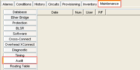
Select Maintenance > Audit in the shelf view to access the audit log (see Figure 5).
-
Ensure that all columns appear.
-
Name the file nodename_audit.html.
Network Diagram
A screen capture from the Network View is helpful, but does not include everything necessary to troubleshoot the network.
The network diagram requires:
-
IP addresses
-
Subnet masks
-
Network topology
-
Cards/ports for each span
If your network uses the Bidirectional Line Switch Ring (BLSR) topology, identify which cards are East-oriented and which cards are West-oriented.
Name the file nodename_diagram.xxx, where xxx represents the file type used.
Circuit List
Click the Circuits tab. Name the file nodename_circuits.html.
Figure 6 – Circuit List 
Node Database Backup
Select the Maintenance tab, and click Backup in the Database section in the shelf view.
Name the file nodename_backup.dat.
Figure 7 – Database Backup 
Inventory List
Click the Inventory Tab. Name the file nodename_inventory.html.
Figure 8 – Inventory 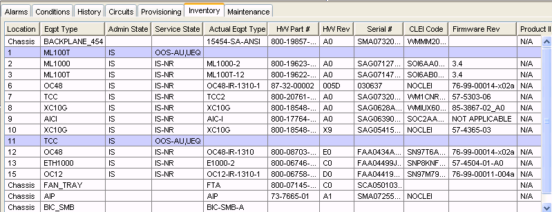
CTC Software Version
You can find the CTC software version in the left side top section of the shelf view (see Figure 9). Name the file nodename_CTC.html.
Figure 9 – Software Version 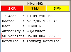
Performance Tab (Monitoring)
Click the Performance tab in the card view. Name the file nodename_cardxxyy_performance.html, where xx represents the slot number, and yy represents the port number.
Figure 10 – Performance 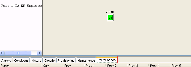
ONS 15454 Multi-service Transport Platforms (MSTP)
In order to troubleshoot issues, you must collect all items listed in the ONS 15454 Multi-service Provisioning Platforms (MSPP) section, and the Metro Planner file.
Metro Planner File
The Cisco Metro Planner software package generates a Metro Planner file for each 15454 MSTP node in the network configuration. The Metro Planner file is usually available from the network configuration designer.
ONS 15454 Multi-Layer (ML) Card
In order to troubleshoot issues, you must collect all items listed in the ONS 15454 Multi-service Provisioning Platforms (MSPP) section in addition to:
-
show tech command output
-
show log command output
-
show cdp neigh command output
ONS 15530/15540
Gather these items:
-
show tech command output
-
show log command output
-
show alarm command output
Related Information
Revision History
| Revision | Publish Date | Comments |
|---|---|---|
1.0 |
05-Jan-2006 |
Initial Release |
Contact Cisco
- Open a Support Case

- (Requires a Cisco Service Contract)
 Feedback