MSTP System APC-OUT-OF-RANGE Alarm Troubleshoot
Available Languages
Contents
Introduction
This document describes the steps used in order to troubleshoot the APC-OUT-OF-RANGE alarm raised on Multiservice Transport Platform (MSTP) systems.
Prerequisites
Requirements
Cisco recommends that you have knowledge of these topics:
- MSTP systems, concepts, and hardware
- Cisco Transport Controller (CTC)
- Cisco Transport Planner (CTP)
- Automatic Power Control (APC) mechanism, such as that it uses Automatic Node Setup (ANS) parameters and the number of active channels used in order to control optical power levels
Components Used
The information in this document is based on these software and hardware versions:
- CTC
- Block Diagrams of Optical Cards
The information in this document was created from the devices in a specific lab environment. All of the devices used in this document started with a cleared (default) configuration. If your network is live, make sure that you understand the potential impact of any command.
Related Products
This document can also be used with these hardware and software versions:
- Cisco ONS 15454 MSTP
- Network Convergence System 2000 (NCS 2000)
Background Information
APC is the greatest feature on Cisco MSTP systems that compensates for changes in optical power levels by Gain and Variable Optical Attenuators (VOA) adjustments of optical cards like amplifiers, demimultiplexer (D-MUX), multiplexer (MUX), Add-Drop cards, and Wavelength Cross Connect Cards.
The APC-OUT-OF-RANGE condition is raised when the APC system fails to regulate the optical levels because of card parameter limitations, insufficient optical power levels, or because of APC Disabled (the APC does not work).
This condition only arises on the ports that can be regulated through VOA or Gain. There are various root causes for this condition, and this document describes the most probable ones.
Troubleshoot APC-OUT-OF-RANGE
Use these methods in order to troubleshoot this condition.
APC-OUT-OF-RANGE on Amplifiers
This alarm can be seen on these optical amplifier built cards:
- 15454-OPT-PRE=
- 15454-OPT-BST=
- 15454-OPT-BST-E=
- 15454-OPT-AMP-C=
- 15454-OPT-AMP17-C=
- 15454-OPT-EDFA-24=
- 15454-OPT-EDFA-17=
- 15454-40-SMR1-C=
- 15454-40-SMR2-C=
APC-OUT-OF-RANGE is generally raised on the output port of the amplifier card.
For example:
- For OPT-PRE, it is seen on the COM-TX port.
- For OPT-BST, it is on the LINE-TX.
- Because SMR2C has two in-built amplifiers, PRE and BST, it can be on the LINE-TX or the EXP-TX or on both.
In order to understand this, check the block diagram of each card from Cisco ONS 15454 DWDM Configuration Guide, Release 9.6.x.
When you see this alarm, check the Total Output Power required as per design and the optical amplifier gain requirement.
Here is the formula to calculate that:
Total output power = Per Channel Power + 10Log (N)
- Where the Per Channel Power = can be obtained from the ANS parameters (Node view > Provisioning > WDM-ANS > Provisioning) or from Card view > Provisioning > Opt.Ampli.Line > Channel Power Ref.
- Where N = The number of active channels. Check the Opt.Ampli.Line field under card view. There should be a number of active channels given for the card.
Consider a scenario where the number of active channels is 10 and the per channel power reference is 2dBm. Then, the Total Output Power = 2 + 10Log (10) = 12dBm.
Now, you must determine how much gain is required in order to achieve this Total Output Power. For this, check how much optical power the card receives. Refer to the block diagram in order to confirm which port to examine. For example, for OPT-PRE, check COM-RX; and for SMR1C, check Line-RX.
If you assume that the received optical power is -10dBm, the gain required is 22dB.
Gain = incoming optical power - total output power required; so, in this scenario, Gain = -10 -12 =-22. You remove the "-" sign because gain is always in +ve.
There are two parameters related to gain on the CTC. One is Gain that is actual current gain used by the card and the other is Gain set point, which is given by the controller card after the calculation is made by same method used here.
At this point, you know there is an alarm on the card, the gain set point should be 22dB, and the actual gain should also be 22dB. Now, you must refer to the amplifier specifications in order to determine if this amount of gain is possible for the card. Refer to this table:

From this table, you can see that for cards like BST, EDFA-17, AMP-17, SMR-2 BST, RAMP-C, and RAMP-CE, a gain of 22dB is not possible due to hardware limitations.
In such cases, look for a 15 minute history performance or a 24-Hours history performance in order to check for optical power levels on receive ports. There might be a degradation in optical power levels that decreased the incoming levels and forced the card for such a gain.
For this scenario, possible solutions are fiber rectification or a design change. A temporary workaround is to try to increase the optical power level with an increase in the gain of the card from the far end if possible; however, this is not recommended, because it can induce errors on the path.
In order to implement a design change, you must update the MPZ file with new loss values and then analyze it. The Cisco Advance Services (AS) Team must help with that. Therefore, the first preference is always fiber rectification.
If after the calculations, you determine that the required Gain set point is 4dB, then what are the possibilities?
Check for the optical performance history on the incoming port, and then maybe a fiber rectification that decreased the losses, or it is possible that you must put an attenuator on the Rx port in order to compensate for a short span and you do not have that. Also check the design file, because if no fiber rectification event happened, then the design file will have attenuator values and you do not have that.
A temporary solution is to use some attenuator pads in order to reach the gain specification for that particular card. Keep the attenuator as low as possible.
If the required gain that you found after calculation falls within the gain range based on the table, then look in conditions on CTC and click retrieve to be sure. There might be some other alarms, such as APC disabled. If not, then check for the APC Domain. In order to do this, go to Network view > Maintenance > APC > Refresh, select the required span, and check for the APC progress State. It should be completed; if it is running and in the same state for a long time or if it is disabled, then there is a problem. APC disabled or APC in a running state for an infinite time means that APC has stopped and the system is not able to make any corrections. There can be many reasons for this, but the most common is a change is the optical power levels of less or more than 3dB. APC stops if changes are more or less than 3dB.
In such cases, contact the Cisco Technical Assistance Center (TAC) because more in depth analysis is required. Log into the Technical Support Website for more information or visit the Cisco Worldwide Contacts page in order to obtain a directory of toll-free Technical Support numbers for your country.
APC-OUT-OF-RANGE on Add-Drop (AD) Cards
There are three types of AD cards available for C-band.
- AD-1C
- AD-2C
- AD-4C
The troubleshoot method is essentially the same for all of the cards. This document focuses only on C-band cards because they are widely used.
APC-OUT-OF-RANGE on the Channel Transmit (CH-TX) Port
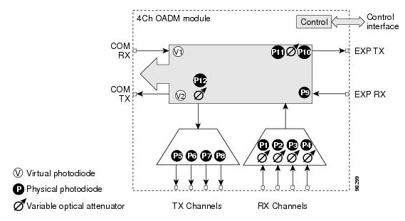
As shown in the block diagram of AD-4C, there is one VOA (P12) for all four Transmit Channels.

In order to check the ANS parameter, go to Node-View > Provisioning > WDM-ANS > Provisioning and check CHAN-TX for the specific slot on which alarm is there.
The APC-OUT-OF-RANGE alarm on this port indicates that the port is unable to achieve the desired optical power level, which is given in the ANS parameters; this might be because of the APC disabled alarm, which does not work when changes are more than +3/-3dBm or can be possible if VOA is not left with attenuation.
In order to start the troubleshoot procedure, note the optical power level of the port on which the alarm is observed. In order to check the optical power level, go to Card View > Provisioning > Optical Chn.
Consider a scenario where the optical power level is -20dBm for CHAN-TX 1. If you check the set point (ANS parameter) and find that it is -12dBm for CHAN-TX 1, it means that you need -12dBm as the channel optical power. However, you have -20dBm in actual.
So in this scenario, you must check the 15-minute history performance of the COM-RX port in order to determine if there is any drop in optical levels because of increased fiber losses. In order to resolve this, you must rectify fiber losses. You can change the set point also, but that should always be the last thing you do.
For further details, contact TAC. Log into the Technical Support Website for more information or visit the Cisco Worldwide Contacts page in order to obtain a directory of toll-free Technical Support numbers for your country.
APC-OUT-OF-RANGE on the Express Transmit (EXP-TX) Port
In the block diagram of the AD card, you can see that there is a VOA on EXP TX. If you look into the ANS parameter, there are set points for COM-RX and COM-TX ports. It is important to understand why it is like that.

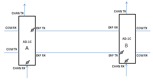
From the diagram, you can understand that you have VOAs on EXP-TX and CHAN-RX ports, and the same applies to all other types of cards. In the ANS parameter, you have a set point of COM-RX and COM-TX.
The set point is achieved when you set the VOA or GAIN. In this case, it is VOA. So the set point of the COM TX of card B as shown in the diagram can be achieved if you regulate the VOA of the EXP-TX port of card A and the VOA of the CHAN RX port of card B.
The set point of COM RX is achieved by the GAIN of a connected amplifier. If there is no amplifier connected, then it is the amplifier of a neighboring node.
Therefore, if there is an APC-OUT-OF-RANGE alarm on the EXP-TX port, then it means the VOA of the EXP-TX is not able to regulate itself to achieve the COM-TX set point of the next card. It can be because of an increase/decrease in the optical power levels at the COM-RX port or because the appropriate optical power levels at the CHAN-RX of card B that is shown in the diagram.
Therefore, you should first check the set point of the COM-TX (go to Node view > Provisioning > WDM-ANS > Provisioning and select the slot). Then check the current optical power level on COM-TX (go to Card view > Provisioning).
APC-OUT-OF-RANGE on SMR Cards
The troubleshoot process for this alarm on the EXP-TX and the LINE-TX of the 40-SMR2-C is the same as the troubleshoot process on Amplifiers. The troubleshoot process for this alarm on the EXP-TX of the 40-SMR1-C is the same as the troubleshoot process on Amplifiers
APC-OUT-OF-RANGE on the LINE-TX of the 40-SMR1-C Card
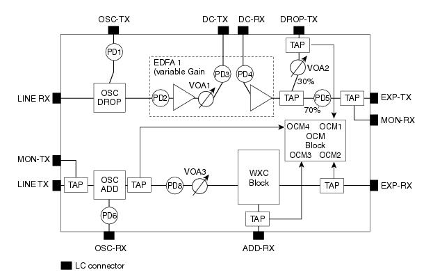
In order to clear this alarm from the Line-TX of the 40-SMR1-C card, it is important to first understand the structure of the card. Here is the block diagram:

As shown in this diagram, there is no amplifier unit between the EXP-RX and the LINE-TX port. The Line-TX port transmits the optical power received on the EXP-RX port.
The WXC block is there in order to equalize and to tune the optical power of each wavelength to a certain level. The optical power required by each wavelength is designed prior and uploaded on the node. These design parameters are called the ANS parameters.
If there is an APC-OUT-OF-RANGE alarm on the Line-TX of the SMR1C card, first look into the set point POWER for the Line-TX, which can be seen from the CTC: go to Node view > Provisioning > WDM-ANS > Provisioning, select the alarmed SMR card, and look for Line-TX > POWER.
Consider a scenario where it is -15dBm. It means that -15dBm of optical power is to be transmitted from the Line-TX for each wavelength or channel. After this, check the alarm on the CTC. If this alarm is against a particular wavelength, look for the optical power on the Line-TX of that wavelength.
For further details, contact TAC.Log into the Technical Support Website for more information or visit the Cisco Worldwide Contacts page in order to obtain a directory of toll-free Technical Support numbers for your country.
Revision History
| Revision | Publish Date | Comments |
|---|---|---|
1.0 |
21-Apr-2014 |
Initial Release |
Contact Cisco
- Open a Support Case

- (Requires a Cisco Service Contract)
 Feedback