Common Issues With Two-Fiber Bidirectional Line Switched Rings
Available Languages
Contents
Introduction
You can encounter several common issues when you configure ONS 15454 nodes as a Bidirectional Line Switched Ring (BLSR). This document addresses such issues, and provides best practice examples to configure a BLSR ring. When you configure a BLSR ring, you can add, remove, and physically re-configure 15454 nodes.
Note: The ONS 15454 supports two-fiber and four-fiber BLSRs with up to 32 15454 nodes, based on software and hardware configuration. BLSRs allocate half the available fiber bandwidth for protection. For example, an optical Carrier-48 (OC-48) BLSR allocates Synchronous Transport Signals (STSs) 1-24 to working traffic, and STSs 25-48 for protection. If a break occurs on one fiber span, working traffic switches to the protection bandwidth (STSs 25-48) on the other fiber spans. Working traffic travels in one direction on STSs 1-24 on one fiber, and on STSs 1-24 in the opposite direction on the second fiber. Working and protection bandwidths must be equal. You can create only Optical Carrier-12 (OC-12) (two-fiber only), or OC-48 and OC-192 BLSRs.
Prerequisites
Requirements
Readers of this document should have knowledge of these topics:
-
Cisco ONS 15454
-
BLSR
Components Used
The information in this document is based on Cisco ONS 15454.
The information in this document was created from the devices in a specific lab environment. All of the devices used in this document started with a cleared (default) configuration. If your network is live, make sure that you understand the potential impact of any command.
Conventions
Refer to the Cisco Technical Tips Conventions for more information on document conventions.
Background Information
This document describes a lab setup with an initial four-node BLSR ring (see Figure 1).
This section illustrates and explains how to configure the BLSR ring. You can use the same procedure to configure BLSR rings of any size up to the maximum limit of 32 nodes.
This section also provides step-by-step instructions to:
-
Add a 15454 node to the BLSR ring, and verify whether existing circuits are added and pass through it.
-
Remove a node.
-
Move one of the OC-48 trunk cards to a different physical slot on the 15454 chassis.
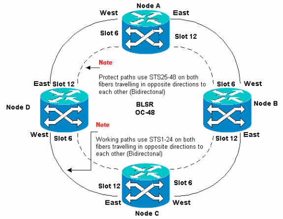
You can create Synchronous Optical Network (SONET) Data Communications Channel (SDCC) terminations on the East and West ports. The fiber of the East port must plug into the fiber of the West port on an adjacent node. Similarly, the fiber of the West port must plug into the fiber of an East port on an adjacent node.
If you configure the East to West connections incorrectly (for example, if you configure East to East or West to West), no error message is displayed. However, traffic fails if the fiber breaks. Traffic fails because the nodes on either side of the fiber break are unable to switch the traffic that rides the bidirectional working paths on STSs 1-24 back onto the protect paths on STSs 25-48.
In order to avoid errors, use a system to assign BLSR ports. You can make the East port the furthest physical slot to the right in the 15454, and the West port the farthest physical slot to the left. For example, in Figure 1, slot 12 is the East port and slot 6 is the West port.
The SONET K1, K2, and K3 bytes carry the information that governs BLSR protection switches. Each BLSR node monitors the K bytes to determine when to switch the SONET signal to an alternate physical path. The K bytes communicate failure conditions and actions taken between nodes in the ring.
Working and Protect Paths
BLSR rings allocate half of the available fiber bandwidth for protection. STSs 1-24 are allocated to traffic on the working spans on both fiber paths. STSs 25-48 are allocated to traffic on protection spans on both fiber paths. Working and protection bandwidths must be equal. You can only provision OC-12, OC-48 and OC-192 BLSRs.
On a normal BLSR ring without a fiber break, STSs 1-24 are used for working traffic on both fiber spans 1 and 2 that travel in opposite directions (see Figure 2):
Figure 2 – Normal BLSR Ring Without a Fiber Break 
The K1 and K2 bytes in the line overhead section of the SONET frame indicate the state of the ring, as this table shows:
| Path Overhead | ||||
|---|---|---|---|---|
| Section Overhead | A1 Framing | A2 Framing | A3 Framing | J1 Trace |
| B1 BIP-8 | E1 Orderwire | E1 User | B3 BIP-8 | |
| D1 Data Com | D2 Data Com | D3 Data Com | C2 Signal Label | |
| Line Overhead | H1 Pointer | H2 Pointer | H3 Pointer Action | G1 Path Status |
| B2 BIP-8 | K1 | K2 | F2 User Channel | |
| D4 Data Com | D5 Data Com | D5 Data Com | H4 Indicator | |
| D7 Data Com | D8 Data Com | D9 Data Com | Z3 Growth | |
| D10 Data Com | D11 Data Com | D12 Data Com | Z4 Growth | |
| S1/Z1 Sync Status/Growth | M0 or M1/Z2 REI-L Growth | E2 Orderwire | Z5 Tandem Connection | |
Here is a breakdown of the K1 bits:
| Request Pre-emption Priority | ||
|---|---|---|
| Bits 1 to 4 | Bits | Priority |
| 1111 | Lockout of Protection (span) [LP-S] or Signal Fail (protection) [SF-P] | |
| 1110 | Forced Switch (span) [FS-S] | |
| 1101 | Forced Switch (ring) [FS-R] | |
| 1100 | Signal Fail (span) [SF-S] | |
| 1011 | Signal Fail (ring) [SF-R] | |
| 1010 | Signal Degrade (protection) [SD-P] | |
| 1001 | Signal Degrade (span) [SD-S] | |
| 1000 | Signal Degrade (ring) [SD-R] | |
| 0111 | Manual Switch (span) [MS-S] | |
| 0110 | Manual Switch (ring) [MS-R] | |
| 0101 | Wait To Restore [WTR] | |
| 0100 | Exerciser (span) [EXER-S] | |
| 0011 | Exerciser (ring) [EXER-R] | |
| 0010 | Reverse Request (span) [RR-S] | |
| 0001 | Reverse Request (ring) [RR-R] | |
| 0000 | No Request [NR] | |
| Bits 5 to 8 | Destination Node ID: These bits indicate the ID of the node to which the K1 byte is destined. The destination node ID is always that of an adjacent node (except for default APS bytes). | |
Here is a breakdown of the K2 bits:
| Bits | Description |
|---|---|
| Bits 1 to 4 | These bits always indicate the Node ID of the node that sources the request. |
| Bit 5 | This bit indicates whether the bridge request K1 bits 1 to 4 is a short path request (0) or a long path request. (1) |
| Bits 6 to 8 | 111 -Line AIS |
| 110 - Line RDI | |
| 101 - Reserved for future use | |
| 100 - Reserved for future use | |
| 011 - Extra Traffic (ET) on Protection Channels | |
| 010 - Bridged and Switched (Br and Sw) | |
| 001 - Bridged (Br) | |
| 000 - Idle |
If a fiber break occurs, the K1 and K2 bytes report the alarm. The K1 and K2 bytes identify the source and destination nodes where the break has occurred, and whose working and protection channels are looped. Working traffic switches to the protection bandwidth (STSs 25-48) on spans 2, 3, and 4.
Figure 3 – Fiber Break 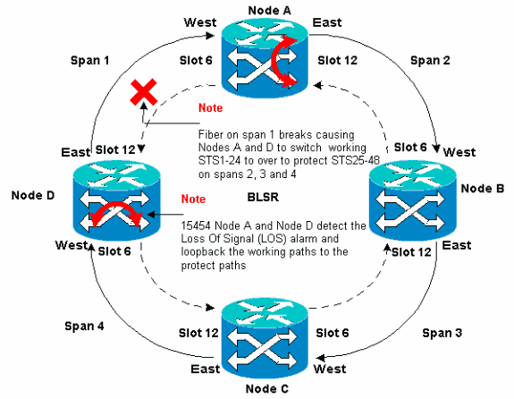
Figure 4 displays the BLSR ring spans 2, 3, and 4 after Nodes A and D detect a fiber break and switch the working paths STSs 1-24 onto the protect paths STSs 25-48.
Figure 4 – BLSR Ring Spans 2, 3, and 4 After Nodes A and D Detect a Fiber Break 
The disruption to traffic is less than a 50 milliseconds when the switch from working to protect fibers occurs.
You must understand the impact of a fiber break on circuits that travel around the BLSR ring. Consider the scenario in Figure 5, where circuits travel on both sides of the ring. Circuits enter and exit at Nodes A and C.
Figure 5 – Impact of a Fiber Break on Circuits 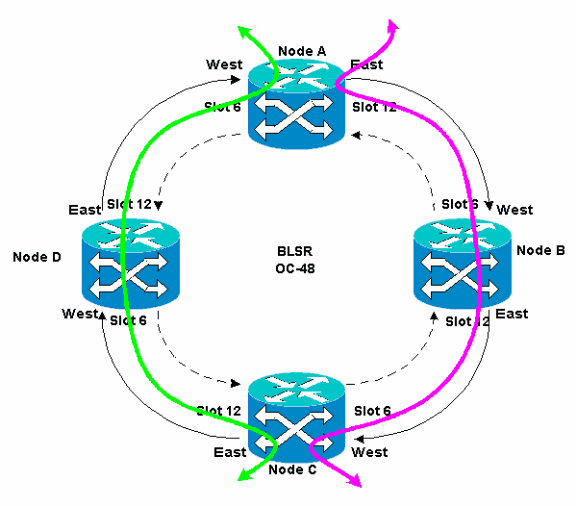
If a fiber break occurs between Node A and Node D, all K1 and K2 bytes change to reflect the status of the fiber between Node A and Node D. The traffic that travels on STSs 1-24, on the left side of the ring, now uses STSs 25-48 on the right side of the ring. The traffic on STSs 25-48 is destined for Node C. However, the traffic must continue to Node D. At Node D, the traffic is bridged and switched back to Node C (see Figure 6).
Figure 6 – Traffic is Bridged and Switched to Node C 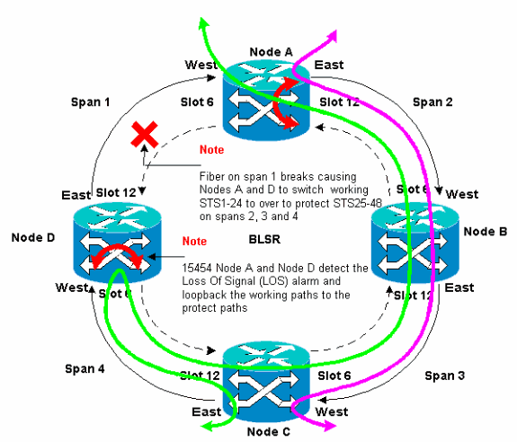
Configure the BLSR Ring
Complete these steps to set up a BLSR ring:
Install the Optical Carrier Cards and Attach the Fibers
Complete these steps:
-
Use the procedures in the Card Installation and Turn-Up section of the 15454 User Documentation to physically install the OC-12 or OC-48 cards. You can install the OC-12 cards in any slot. However, you must install the OC-48 cards only in the high speed slots 5, 6, 12, or 13.
-
Allow the cards to boot.
-
Attach the fiber to the cards.
Ensure that the ACT LED on the card you installed turns green.
Create the DCC Terminations to the Cards
Complete these steps:
-
Log into the first node in the BLSR.
-
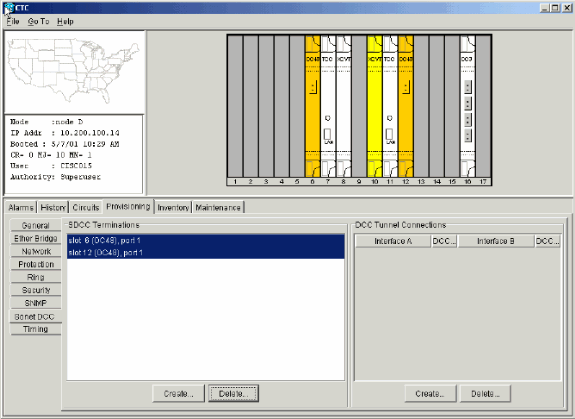
Select Provisioning > Sonet DCC.
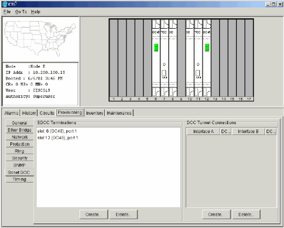
The SDCC Terminations panel displays:
Figure 7 – The SDCC Terminations Panel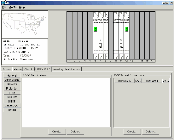
-
Click Create in the SDCC Terminations section.
The Create SDCC Terminations dialog box displays:
Figure 8 – The Create SDCC Terminations Dialog Box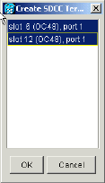
-
Hold the CTRL key down, and click the two slots or ports that must serve as the BLSR ring ports at the node. For example, slot 6 (OC-48) port 1 and slot 12 (OC-48) port 1 (see Figure 8).
Note: The ONS 15454 uses the SONET section layer DCC (SDCC) for data communications. The ONS 15454 does not use the line DCCs. Therefore, the line DCCs are available to tunnel DCCs from third-party equipment across ONS 15454 networks.
-
Click OK.
The slots or ports are listed in the SDCC Terminations section:
Figure 9 – The Slots or Ports are Listed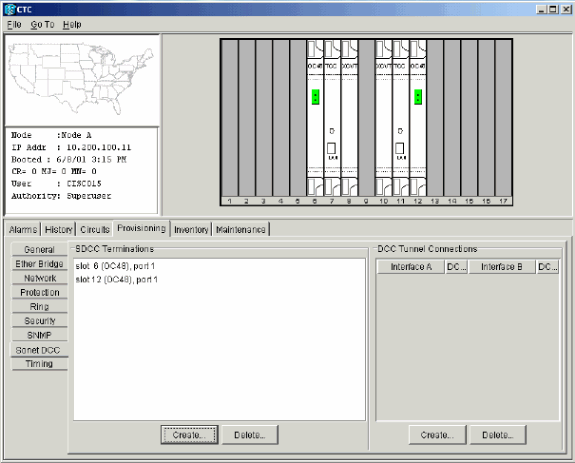
Enable the Ports to the Cards
Complete these steps:
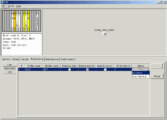
-
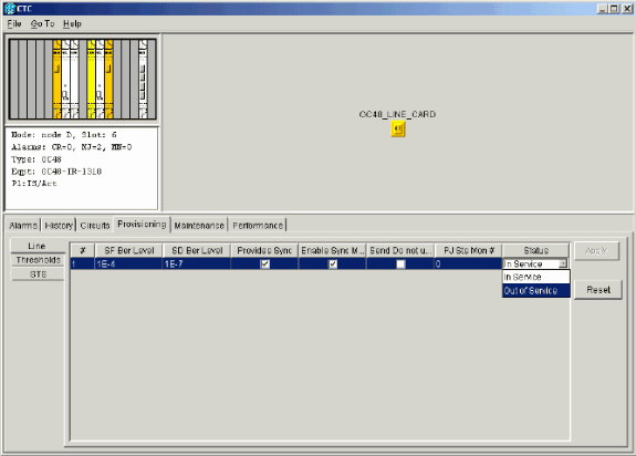
Double-click one of the optical cards that you configured as an SDCC termination.
-
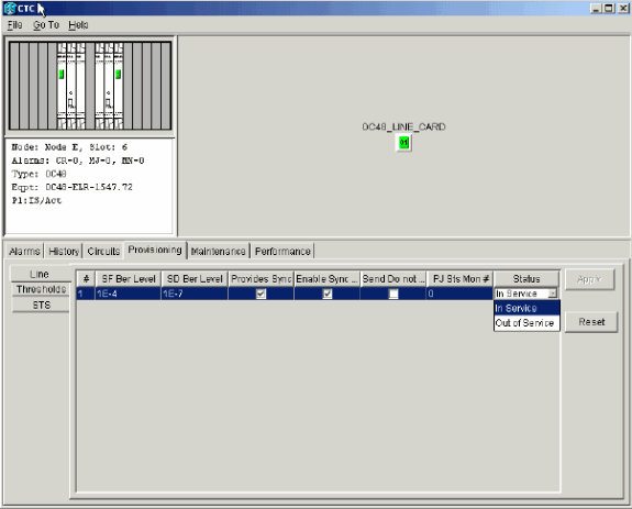
Select Provisioning > Line.
-
Select In Service in the Status column.
Figure 10 – Select the In Service Option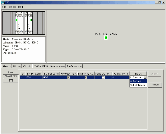
-
Repeat steps 1 through 3 for the other optical card configured as an SDCC termination, and for each node in the BLSR ring.
Configure the BLSR Ring
Complete these steps:
-
Log into one of the BLSR nodes.
-
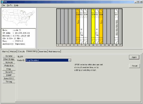
Select Provisioning > Ring.
Ensure that all circuits for the optical cards for the BLSR ring are deleted. You must start with the BLSR ring disabled:
Figure 11 – Start With the BLSR Ring Disabled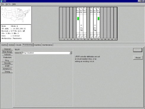
-
Type an identifier for the node in the Node ID field of the BLSR section.
The Node ID identifies the node to the BLSR ring. You can have up to 16 different Node IDs. Ensure that you assign unique Node IDs to all nodes in your BLSR ring.
Figure 12 – Assign Unique Node IDs for Each Node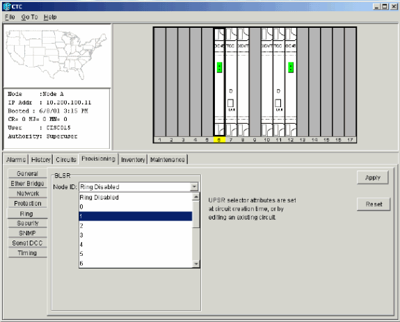
-
Select a Node ID.
The other BLSR fields are displayed.
-
Set these BLSR properties (see Figure 13):
-
Ring ID—Assign an identifier for the ring. Ensure that it is a number between 0 and 255. You must use the same Ring ID for all nodes in the same BLSR.
-
Reversion time—Specify the amount of time after which the working traffic must revert back to the original working path. The default value is five minutes.
-
East Port—Select the required port as the East port from the drop-down list. Typically, the East Port is the highest available slot on the right of the 15454.
-
West Port—Select the required port as the West port from the drop-down list. Typically, the West Port is the lowest available slot on the left of the 15454.
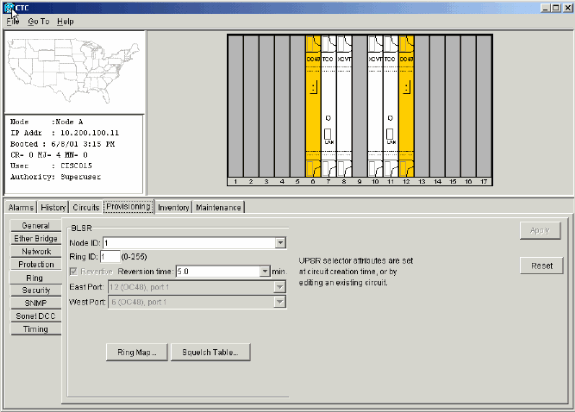
Figure 14 illustrates the configuration of Node A.
Figure 14 – Node A Configuration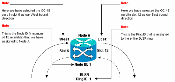
-
-
Click Apply.
The BLSR Map Ring Change dialog box displays:
Figure 15 – The BLSR Map Ring Change Dialog Box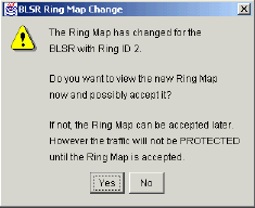
-
Click Yes.
The BLSR Ring Map dialog box displays:
Figure 16 – The BLSR Ring Map Dialog Box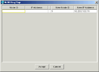
-
Click Accept.
The BLSR Ring Map panel displays the IP address 10.200.100.11 for Node A, which is the first 15454 node in the BLSR ring. The node is added to the BLSR ring map. The Default K alarms are displayed until you configure all nodes in the ring:
Figure 17 – The Default K Alarms
-
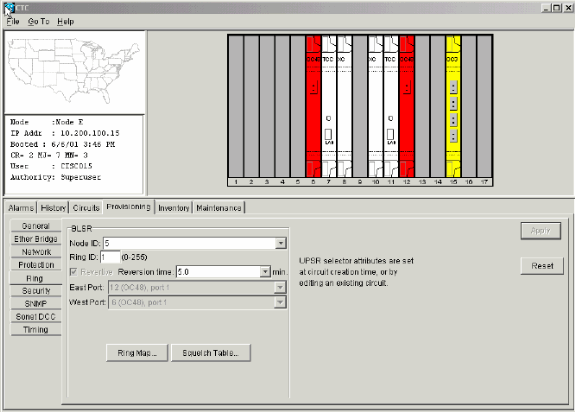
Complete Steps 2 through 6 for the other three nodes that form the four-node BLSR ring. Figure 18 shows the BLSR configuration window for Node B. Notice that it has a different Node ID, but the same Ring ID:
Figure 18 – BLSR Configuration Window for Node B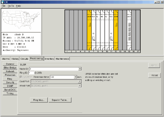
Figure 19 represents the configuration of Node B.
Figure 19 – Node B Configuration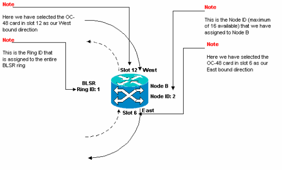
-
Click Apply.
The BLSR Ring Map dialog box displays:
Figure 20 – Add the Second Node to the BLSR Ring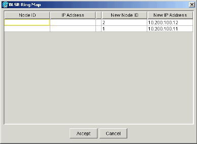
-
Click Accept.
-
Configure Node C.
Figure 21 – BLSR Configuration for Node C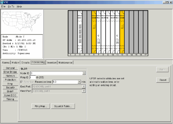
Figure 22 represents the configuration of Node C.
Figure 22 – Node C Configuration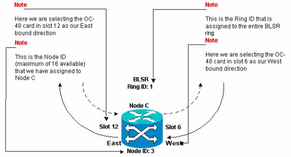
-
Click Apply.
The BLSR Ring Map dialog box displays:
Figure 23 – Add the Third Node to the BLSR Ring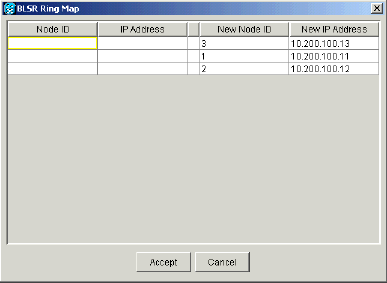
-
Click Accept.
-
Configure Node D.
Figure 24 – BLSR Configuration for Node D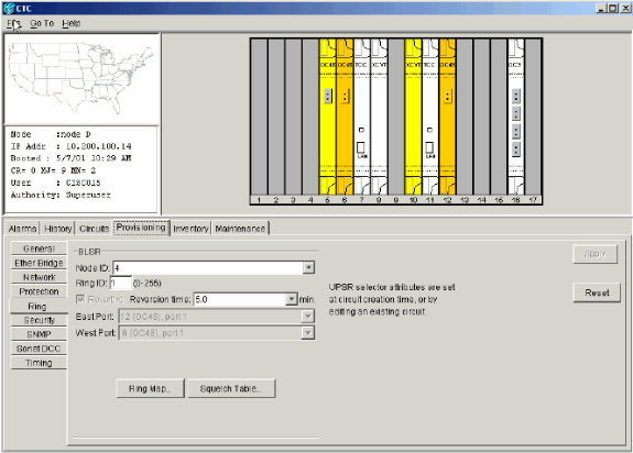
Figure 25 represents the configuration of Node D.
Figure 25 – Node D Configuration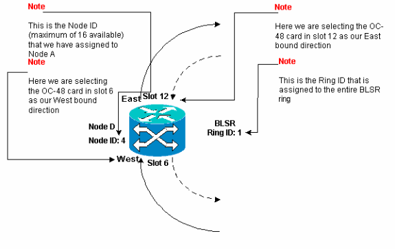
-
Click Apply.
The BLSR Ring Map dialog box displays:
Figure 26 – Add the Fourth Node to the BLSR Ring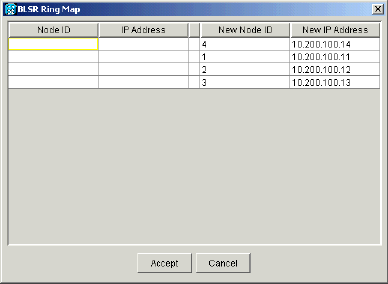
-
Click Accept.
-
Switch to the network view to verify whether the Default K alarms are cleared.
-
Use normal test procedures to test the BLSR. Here are a few steps you can use:
-
Log into a node, and select Maintenance > Ring.
-
Select MANUAL RING from the East Operation list, and click Apply. Verify whether traffic switches normally.
-
Select Clear from the East Operation list, and click Apply.
-
Repeat steps 1 through 3 for the West Operation.
-
Pull fibers at one node, and verify whether traffic switches normally.
-
Set up Timing for the Nodes in the BLSR Ring
After you configure the SONET DCC, you need to set the timing for the node. Refer to the Setup ONS 15454 Timing section of the 15454 User Documentation for step-by-step procedures. Refer to ONS 15454 Timing Issues for general information about ONS 15454 timing.
Add and Drop BLSR Nodes
This section provides procedures to add and drop BLSR nodes for v2.x.x software levels. If you use the latest v5.0 software level, refer to the v5.0 documentation for procedures to add and drop BLSR nodes.
In order to add or drop a node, you need to perform a protection switch with a force operator that routes traffic away from the span where service is performed.
Here is an example to demonstrate how to non-disruptively configure and then add a fifth node, Node E, to the four-node BLSR ring. The example also indicates how to verify whether correct circuits are added to Node E.
Figure 27 – Example to Add a Fifth Node 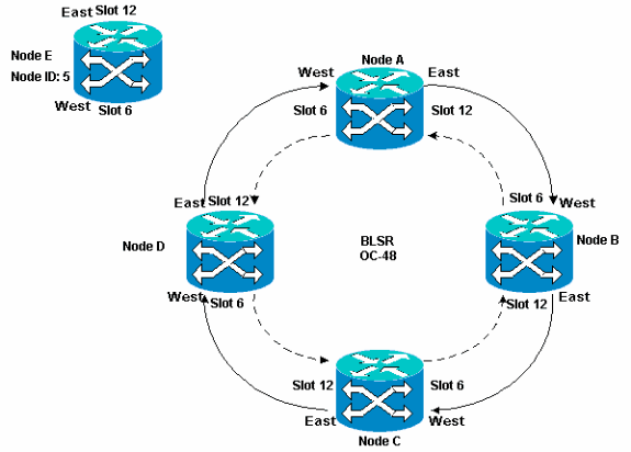
The example also demonstrates how to non-disruptively remove Node E from the BLSR ring. The example shows you how to revert to your original four-node lab setup, and verify whether the circuits are configured correctly.
Note: You can add or remove only one node at a time.
Add a Node
When you want to add a node to your BLSR ring, ensure that you log into the system locally in order to minimize traffic disruptions. Complete these steps:
-
Install the optical cards in the ONS 15454 that you want to add to the BLSR.
Ensure that fiber cables are available to connect to the cards.
-
Run test traffic through the node to ensure the cards function properly.
-
Log into the node from which you want to connect to the new Node E through its East port (Node D in the lab setup).
-
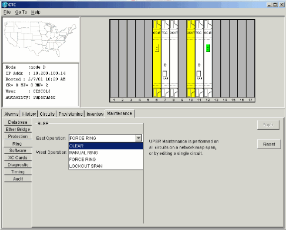
Force traffic on the East port. Complete these steps:
-
Select Maintenance > Ring.
-
Click FORCE RING from the East Operation list.
Figure 28 – Force Traffic on the East Port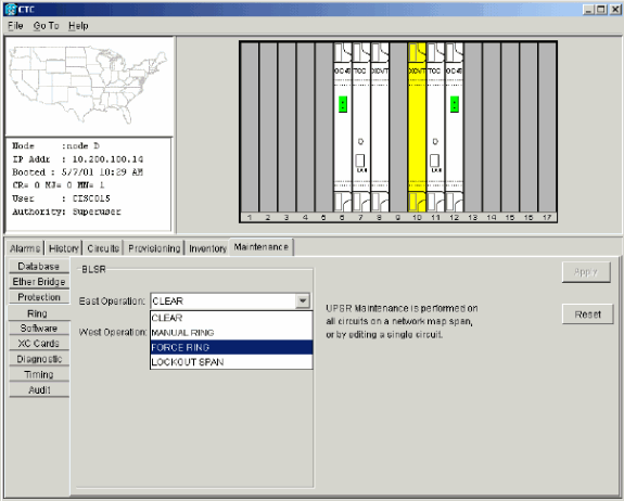
-
Click Apply.
A force switch request alarm is generated for the East port OC-48 card:
Figure 29 – The Force Switch Request Alarm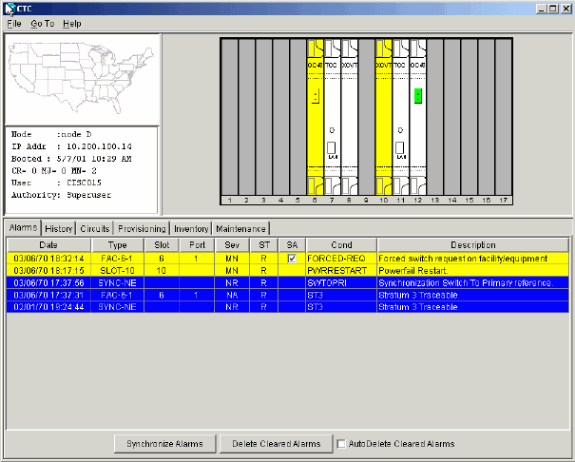
The force switch request alarm is normal.
 Caution: Traffic is unprotected during a protection switch.
 -
Log into the node that must connect to the new node through its West port (Node A in the lab setup).
-
-
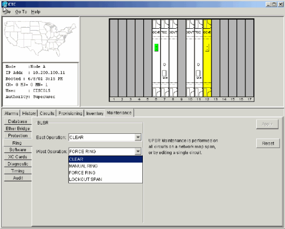
Force traffic on the West port. Complete these steps:
-
Select Maintenance > Ring.
-
Click FORCE RING from the West Operation list.
Figure 30 – Force Traffic on the West Port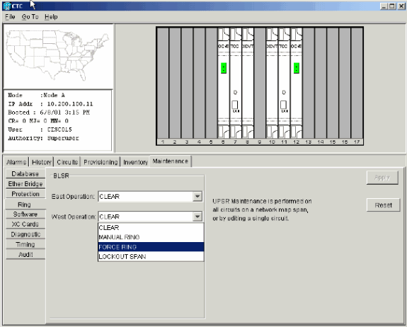
-
Click Apply.
A confirmation message displays that indicates your East and West port directions are configured correctly on the BLSR ring so that traffic can switch correctly:
Figure 31 – Confirmation Message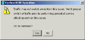
A force switch request alarm is generated for the East port OC-48 card:
Figure 32 – The Force Switch Request Alarm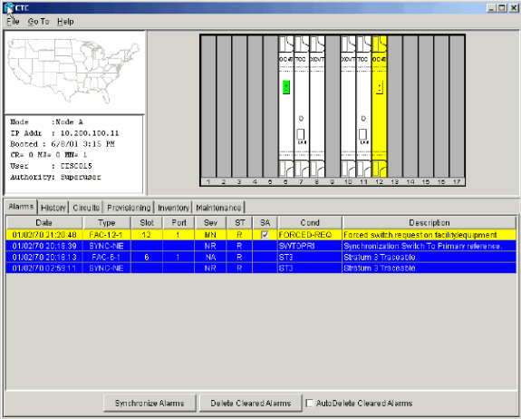
The force switch request alarm is normal.
 Caution: Traffic is unprotected during a protection switch.
-
-
Log into the new node, and complete these BLSR setup steps:
-
Remove the fiber connections from Node D and Node A that connect directly to the new Node E.
-
Remove the East fiber from Node D (slot 12) that must connect to the West port of the new Node E (slot 6).
-
Remove the West fiber from Node A (slot 6) that must connect to the East port of the new Node E (slot 12).
-
-
Replace the removed fibers with fibers connected to the new Node E. Connect the West port to the East port, and the East port to the West port.
-
Log out of the Cisco Transport Controller (CTC).
-
Log into CTC again.
-
Wait for the BLSR Ring Map Change dialog box to display.
Note: If the BLSR Ring Map Change dialog box is not displayed, select Provisioning > Ring, and click Ring Map.
Figure 37 – The BLSR Ring Map Change Dialog Box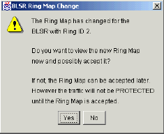
-
Click Yes.
The BLSR Ring Map dialog box displays:
Figure 38 – The BLSR Ring Map Dialog Box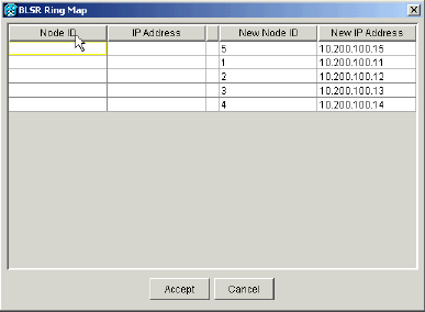
-
Click Accept.
-
Return to the Network view, and click the Circuits tab.
Wait until your network discovers all the circuits. The circuits that pass through the new node are indicated as incomplete. The Circuits window displays one span less than the total number of spans for the circuits:
Figure 39 – One Span Less Than the Total Number of Spans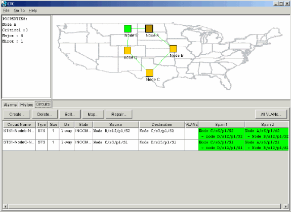
-
Right-click Node E, and select Update Circuits from the shortcut menu.
Figure 40 – Update Circuits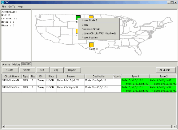
A Circuits Update confirmation message displays that indicates the number of networks added to Node E:
Figure 41 – Circuits Update Confirmation Message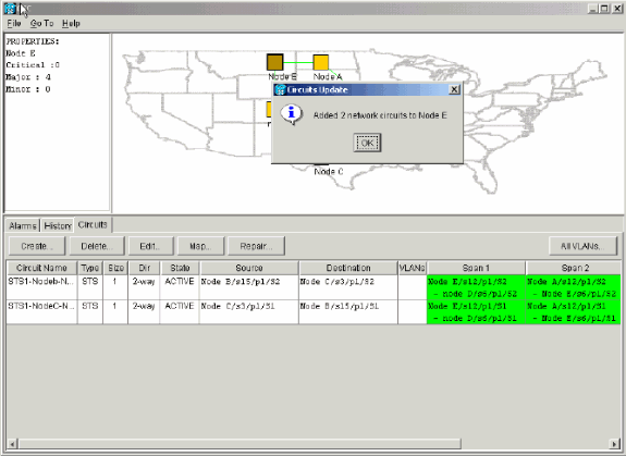
-
Select the Circuits tab, and ensure that the network does not contain any incomplete circuits.
-
Select a circuit, and click Map.
-
Ensure that the circuits pass through the new Node E:
Figure 42 – Ensure That the Circuits Pass Through the New Node E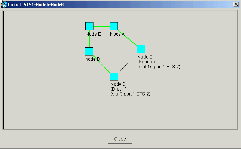
-
Clear the protection switch.
You must clear the protection switch for Node D that uses its East port to connect to new Node E, and for Node A that uses its West port to connect to new node E. Complete these steps:
Remove a Node
 Caution: This procedure minimizes traffic outages when you delete nodes. However, you can lose traffic when you delete and re-create circuits that originated or terminated on a node you remove.
Complete these steps:
-
Select the node that you want to remove, and delete all the circuits that originate or terminate in that node. For example, if you want to remove Node E from the lab setup, complete these steps:
-
Click the Circuits tab.
-
Hold down the CTRL key, and click to select multiple circuits that you need to delete.
-
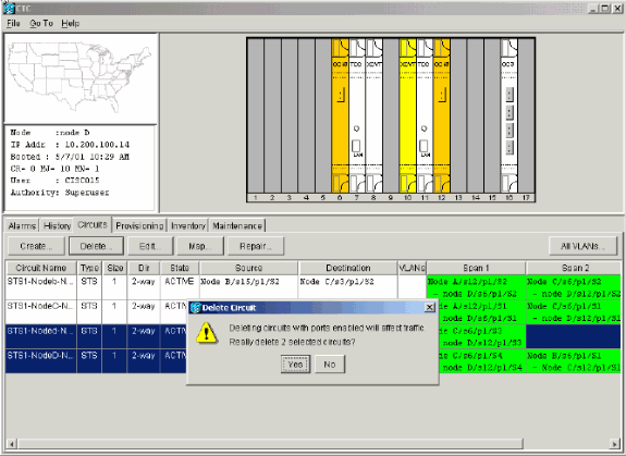
Click Delete.
You are prompted to confirm the deletion:
Figure 45 – Delete Circuits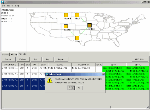
-
Click Yes.
A confirmation message displays:
Figure 46 – Confirmation Message for Circuit Deletion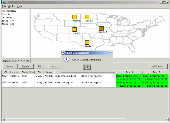
-
If a multidrop circuit contains drops at the node that you want to remove, click Edit.
-
Remove the drops.
Note: Do not log into the node that you want to remove.
Note: If a circuit has multiple drops, delete only the drops that terminate on Node E.
-
-
Manually switch traffic away from the ports of the nodes adjacent to the node you want to remove. The adjacent nodes are disconnected when the node is removed. Complete these steps:
-
Open Node D, which is connected through its East port to Node E.
-
Select Maintenance > Ring.
-
Click FORCE RING from the East Operation list.
-
Click Apply.
Figure 47 – Force traffic on the East Port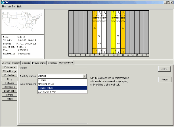
You are prompted to confirm the action.
-
Click Yes.
Figure 48 – Confirm the Operation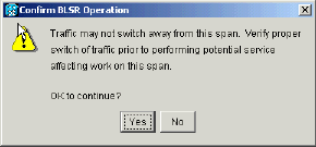
-
Open Node A, which is connected through its West port to Node E.
-
Select FORCE RING from the West Operation list.
-
Click Apply.
Figure 49 – Force traffic on the West Port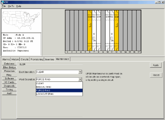
You are prompted to confirm the action.
Figure 50 – Confirm the Operation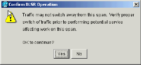
 Caution: Traffic is unprotected during the protection switch.
-
-
Remove any fiber connections that exist between Node E and its neighbors, Node A and Node D.
-
Reconnect the two adjacent nodes.
-
Wait for the BLSR Map Ring Change dialog box to display.
Note: If the BLSR Map Ring Change dialog box does not display, select Provisioning > Ring, and click Ring Map.
Figure 51 – The BLSR Map Ring Change Dialog Box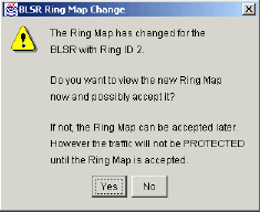
-
Click Yes.
The BLSR Ring Map dialog box displays:
Figure 52 – The BLSR Ring Map Dialog Box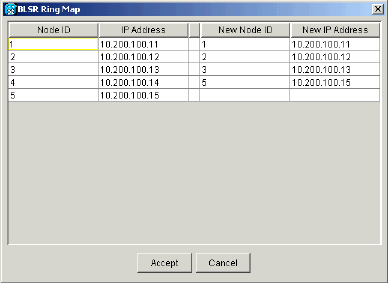
-
Click Accept.
-
One by one, delete and re-create each circuit that originated or terminated on Node E.
-
Clear the protection switches on the adjacent nodes. Complete these steps:
-
Open Node D with the protection switch on its East port.
-
Select Maintenance > Ring.
-
Click CLEAR from the East Operation list.
-
Click Apply.
Figure 53 – Clear the Protection Switch from the East Port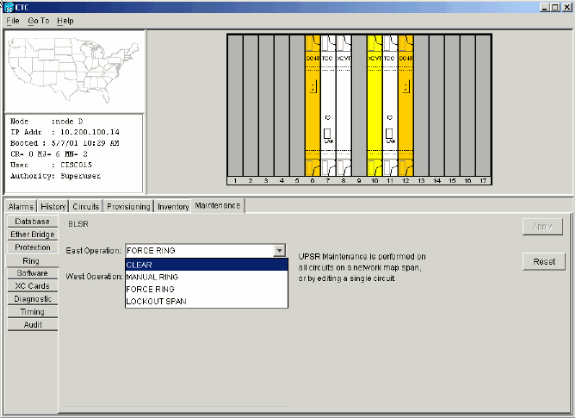
-
Open the node with the protection switch on its West port.
-
Select Maintenance > Ring.
-
Click CLEAR from the West Operation list.
-
Click Apply.
Figure 54 – Clear the Protection Switch from the West Port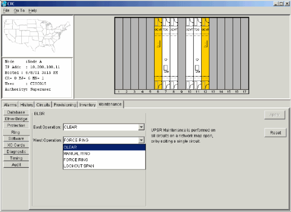
-
-
Check whether a Building Integrated Timing Supply (BITS) clock is used at each node.
-
If BITS is not used, ensure that the synchronization is set to one of the eastbound or westbound BLSR spans on the adjacent nodes.
-
If the node you removed (Node E) was the BITS timing source, use a new node as the BITS source. Alternatively, select internal synchronization at one node from which all other nodes can derive their timing.
-
-
Select the Circuits tab, and ensure that no incomplete circuits are present.
Figure 55 – Ensure that No Incomplete Circuits are Present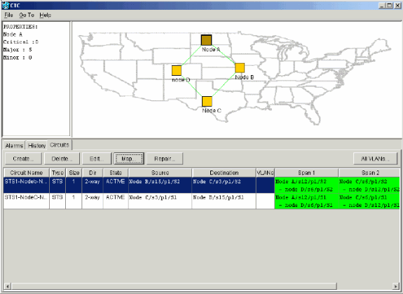
-
Click the Map tab.
-
Verify whether the circuits are routed correctly.
Figure 56 – Verify Whether the Circuits are Routed Correctly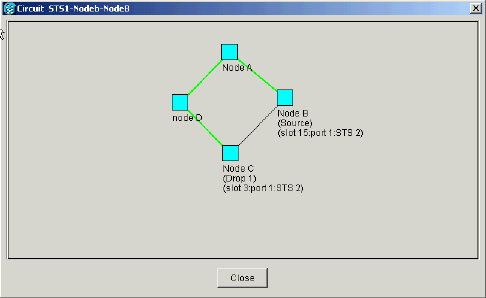
Move a BLSR Trunk Card
Note: You must drop the nodes one by one from the current BLSR ring in order to rearrange the trunk cards. Remember that this procedure affects service, and applies to all BLSR nodes where cards change slots. Review all the steps before you proceed.
In the four-node OC-48 BLSR lab setup in Figure 57, Node D is temporarily removed from the active BLSR ring. In addition, the OC-48 card in slot 6 is moved to slot 5, and the OC-48 card in slot 12 is moved to slot 6.
Figure 57 – Four-Node OC-48 BLSR Lab Setup 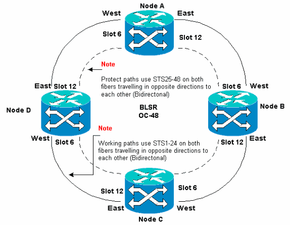
Move the BLSR Trunk Card to a Different Slot on the 15454 Chassis
This section explains how to move one BLSR trunk card to a different slot. Use this procedure for each card you want to move. Although the procedure is for OC-48 BLSR trunk cards, you can use the same procedure for OC-12 cards.
Note: The ONS 15454 nodes must use CTC Release 2.0 or later, and cannot have active alarms for the OC-48 or OC-12 cards or for the BLSR configuration.
-
Force traffic away from the node where you want to switch the trunk card. Complete these steps:
-
Log into the Node C connected through its East port to the Node D where you want to move the trunk card.
-
Select Maintenance > Ring.
-
Click FORCE RING from the East Operation list.
-
Click Apply.
Figure 58 – Force Traffic on the East Port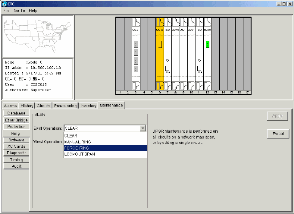
You are prompted to confirm the action.
Figure 59 – Confirm BLSR Operation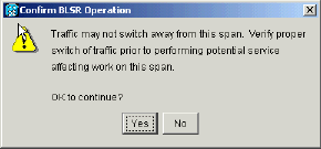
-
Click Yes.
When you perform a force switch, a manual force switch request alarm is generated:
Figure 60 – The Manual Force Switch Request Alarm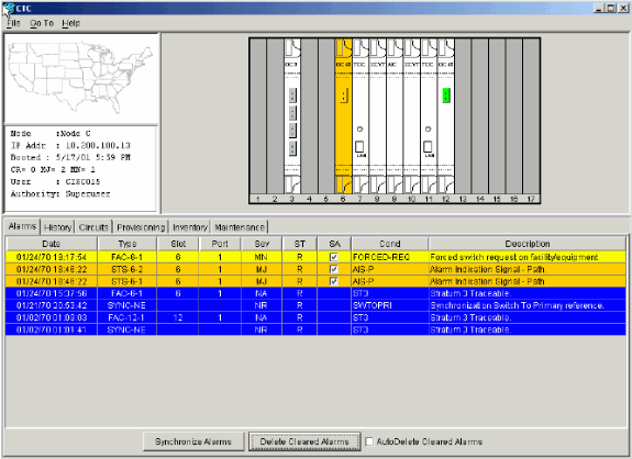
The force switch request alarm is normal.
 Caution: Traffic is unprotected during a protection switch.
 -
Log into Node A that is connected through the West port to Node D where you want to move the trunk card.
-
Select Maintenance > Ring.
-
Click FORCE RING from the West Operation list.
-
Click Apply.
Figure 61 – Force Traffic on the West Port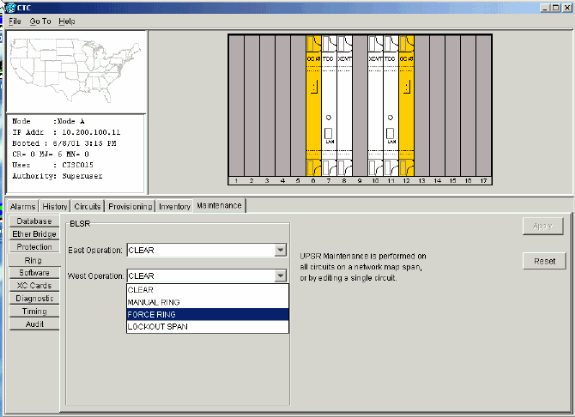
You are prompted to confirm the action.
Figure 62 – Confirm BLSR Operation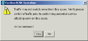
-
Click Yes.
-
-
Log into Node D where the OC-48 trunk card you want to move is installed.
-
Click the Circuits tab.
Figure 63 – Select the Circuits Tab for Node D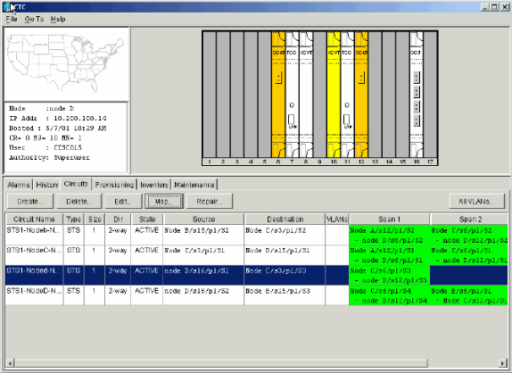
-
Record the provisioning information of the affected circuits. You need this information to restore the circuits later.
-
Delete the circuits that pass through the card you want to move. Complete these steps:
-
Delete the SONET DCC termination on the card you want to move. Complete these steps:
-
Disable the ring on the node you want to move. Complete these steps:
-
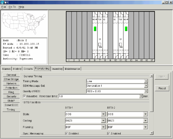
Select Provisioning > Timing, and set timing to Internal Clock if the OC-48 card is a timing source.
Figure 69 – Set the Timing to Internal Clock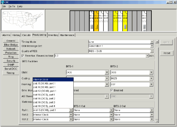
-
Place the port(s) on the card out of service. Complete these steps:
-
Physically remove the OC-48 card in slot 12 and move it to its new location in slot 5.
-
Insert the card into its new slot and wait for the card to boot.
-
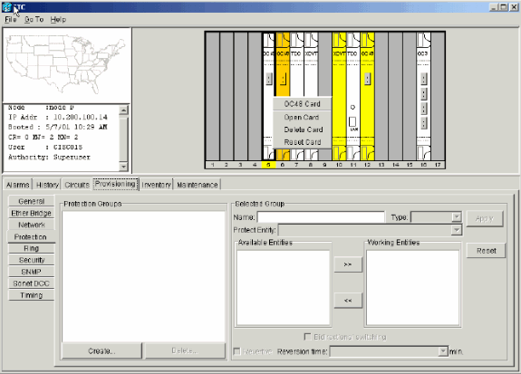
Delete the OC-48 card details from the original slot 12. For this, you must right-click the card in node view, and select Delete from the shortcut menu.
Figure 72 – Delete the OC-48 Card from the Original Slot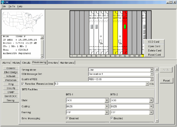
You are prompted to confirm the deletion:
Figure 73 – Confirm the Deletion
-
Place the OC-48 card in slot 5 port(s) back in service. Complete these steps:
-
Complete the steps listed in the Configure the BLSR Ring section of this document to enable the BLSR ring with the same OC-48 cards (in their new slots) and ports for East and West.
-
Manually re-enter the circuits that you deleted.
For more information on how to provision circuits, refer to the Creating and Provisioning Circuits section of the ONS 15454 User Documentation.
-
Enable the timing parameters on the card again, if you use line timing and the card you moved is a timing reference.
Figure 76 – Enable the Timing Parameters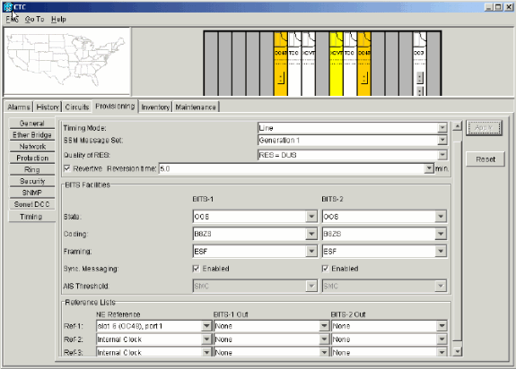
Alarms Associated with BLSR Rings
This section lists the alarms associated with BLSR rings.
Default K Bte Alarm
The Default K Byte Received (DFLTK) alarm occurs when a BLSR is not properly configured. For example, the alarm occurs when a four-node BLSR has one node configured as Unidirectional Path Switched Ring (UPSR). A node in a UPSR or linear configuration does not send the two valid K1/K2 Automatic Protection System (APS) bytes that the system configured for BLSR anticipates. The BLSR configuration considers one of the bytes sent as invalid. The receiving equipment monitors the K1/K2 bytes for link-recovery information.
Figure 77 – The Default K Byte Received (DFLTK) Alarm 
The alarm can also occur when you add a new node for which a new ring map is not accepted. The procedure to troubleshoot DFLTK is often similar to the procedure to troubleshoot BLSROOSYNC. For more information, refer to the DFLTK section of the 15454 User Documentation.
BLSR Out of Synchronization Alarm
Figure 78 – The BLSROSYNC Alarm 
The BLSR Out Of Sync (BLSROSYNC) alarm occurs when you must update the mapping table. In order to clear the alarm, you must create a new ring map that must be accepted. For more information, refer to the BLSROOSYNC section of the 15454 User Documentation.
Related Information
Contact Cisco
- Open a Support Case

- (Requires a Cisco Service Contract)












 Feedback