Adding and Dropping Nodes in a BLSR Ring
Available Languages
Contents
Introduction
This document explains how to add and remove Networks Elements (NEs) in a Bidirectional Line Switched Ring (BLSR).
Note: You can add only one node to a BLSR at a time.
Prerequisites
Requirements
There are no specific requirements for this document.
Components Used
This document is not restricted to specific software and hardware versions.
The information in this document was created from the devices in a specific lab environment. All of the devices used in this document started with a cleared (default) configuration. If your network is live, make sure that you understand the potential impact of any command.
Conventions
For more information on document conventions, refer to the Cisco Technical Tips Conventions.
Background Information
 Caution: This procedure affects service. Perform this procedure during a maintenance window because the procedure involves protection switching. Disruptions of up to three minutes are possible for any Ethernet traffic due to Spanning Tree re-convergence. All other traffic endures up to a 50ms hit.
This procedure assumes that the new node is racked and powered with all cards installed, and that you have completed provisioning. Provisioning includes general issues, network, timing, SONET Data Communications Channel (SDCC), BLSR ring provisioning and putting optical ports in service. Before you begin the procedure, perform these steps:
-
Run test traffic through the node per NTP-A175 or NTP-A176 based on the BLSR type.
-
Identify and tag all involved fibers.
-
Resolve any critical or major alarms. You can identify these alarms from the Alarms tab in Network view.
Add Nodes to a BLSR Ring
This section uses a lab setup with three nodes (Node1, Node2 and Node3). Here is an example that shows how to add a fourth node (Node4).
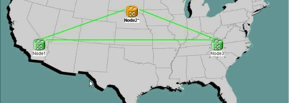
This procedure involves these steps:
Step 1: Confirm BLSR Ring Provisioning
In a BLSR ring, you must fiber the NEs in an east-west configuration around the ring. Connect the east card of one node to the west card of the adjacent node, and vice versa. The optics trunk card furthest to the right in the shelf is normally the east card, and the card furthest to the left is normally the west card.
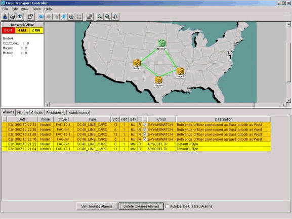
Ensure that the east-west provisioning is correct before you begin the procedure. Click on the Alarms tab in Network view to check whether any BLSR-related alarms are present. If you find any such alarms, clear the alarms before you proceed.
Step 2: Check Circuit Integrity
Next, check the integrity of the circuits on the ring.
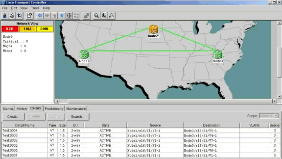
In Network view, confirm that all circuits show up in an active state. If any circuits are in an incomplete state, refer to Best Practices When Configuring Circuits on the ONS 15454 and resolve the issue.
Step 3: Initiate a Protection Switch
After you confirm the configuration of the ring, you must switch traffic away from the span where you insert the new node. First, go to the node that connects to the new node through the east port. Here, Node3 connects to the new node.
 Caution: A forced protection switch can cause service disruption if the rest of the ring is not error-free. Check the Performance Monitoring (PM) statistics for the other optics cards in the ring. In order to check PM statistics:
-
Log into each shelf in the ring.
-
Click on a BLSR optics card.
-
Select the Performance tab.
-
Click Refresh.
You can expect to see zeros in all fields if the span runs without errors. Traffic is unprotected during a forced protection switch.
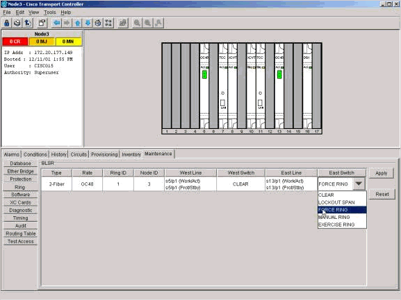
From the Shelf view, click the Maintenance/Ring (Maintenance/BLSR in later software versions) tab. From the East Switch list, choose Force Ring > Apply to force traffic away from the east span.
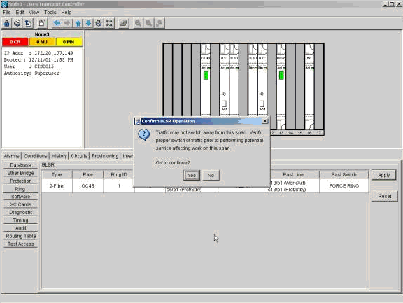
Click Yes in the confirmation dialog box.
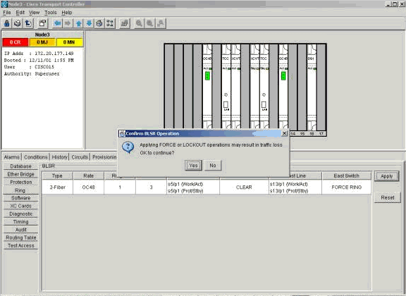
Select Yes again.
Now go to the Shelf view of the node that connects to the new node through the west port. Here, Node1 connects to the new node.
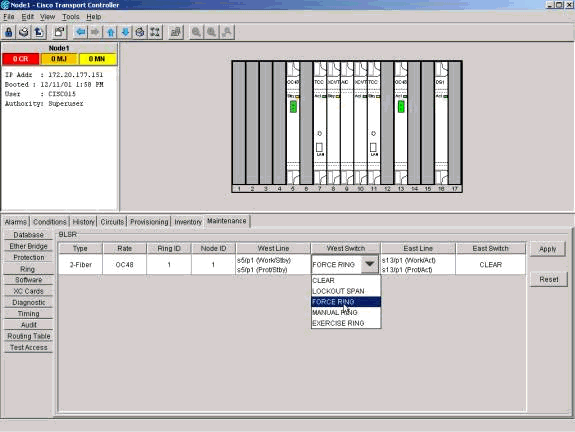
Click the Maintenance/Ring (Maintenance/BLSR in later software versions) tab. From the West Switch list choose Force Ring > Apply. Click Yes in the two confirmation dialog boxes. Thus, you force traffic away from the west span.
Step 4: Connect the New Node
Now you can open this span and connect the new node (Node4).
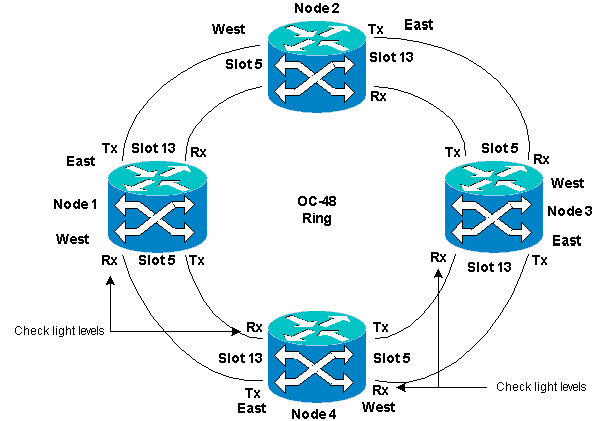
Remove the east fibers from the node that connects to the new node through the east port. Connect the east fibers to the west port of the new node. Remove the west fibers from the node that connects to the new node through its west port. Connect the west fibers to the east port of the new node. Here, you connect:
-
Slot 13 Node3 to Slot 5 Node4
-
Slot 13 Node4 to Slot 5 Node1
In each case, first connect only Tx fibers and check levels before you connect the Rx fibers. You can find Rx levels in the Card Reference section of the Cisco ONS 15454 Troubleshooting Guide, Release 5.0.
Step 5: Re-launch CTC
Now close CTC, and launch CTC again to any node in the ring.
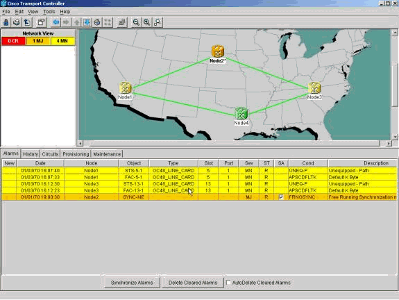
At this point, you can see the Path Unequipped (UNEQ-P) and APSCDFLTK alarms on the optics cards adjacent to the new node. The occurrence of these alarms is normal.
Step 6: Accept the New Ring Map
The next step is to accept the new ring map.
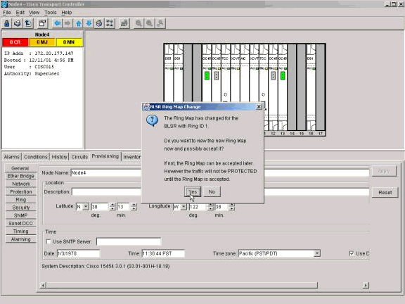
Wait for the BLSR Ring Map Change dialog box to appear. Click Yes to view the new ring map.
If the BLSR Ring Map Change dialog box does not appear:
-
Go to the Shelf view of the new node.
-
Select the Provisioning/Ring (Provisioning/BLSR in later software versions) tab.
-
Click in the Type field to highlight the ring information.
-
Click Ring Map.
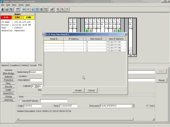
When you are sure that the IP addresses match the node IDs, clickAccept to clear the APSCDFLTK alarms.
Step 7: Update Circuits
Next, you must update the circuits. Go into the Network view and wait until CTC discovers all circuits.
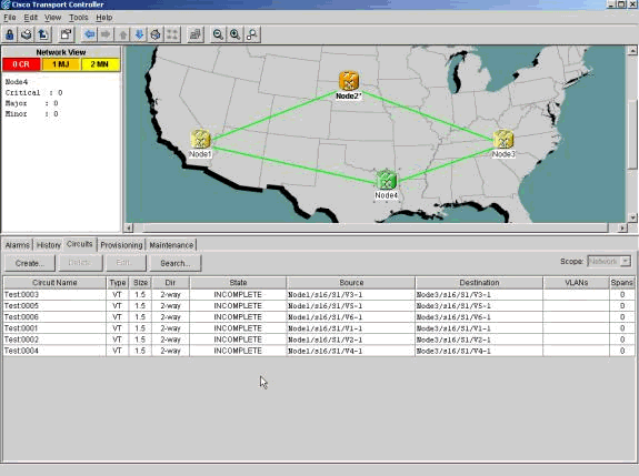
Any circuits that pass through the new node show up as Incomplete. Note the number of incomplete circuits.
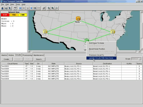
Right-click the new node, and select Update Circuits With New Node from the menu.
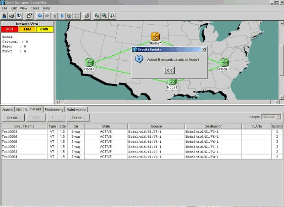
Ensure that the number of updated circuits matches the number of incomplete circuits that you noted previously. Confirm that all circuits are active. If either case is untrue, re-run Update Circuits With New Node.
Note: At this point, ensure that the UNEQ-P alarms are clear.
Step 8: Clear Protection Switches
The last step in the procedure is to clear the protection switch you initiated in Step 3.
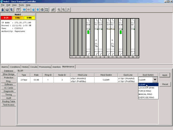
Log into the node through the east port to connect to the new node. In the Provisioning/Maintenance tab, choose Clear from the East Switch list, and click Apply.
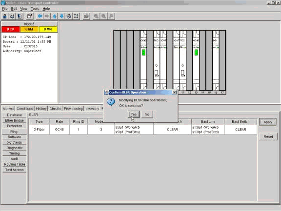
Click OK in the confirmation dialog box. Repeat the action for the node through the west port to connect to the new node. Choose Clear from the West Switch list.
Remove Nodes from a BLSR Ring
This procedure is service-affecting and should be performed during a maintenance window. Disruptions of up to three minutes are possible for any Ethernet traffic due to spanning tree re-convergence. All other traffic endures up to a 50ms hit for each protection switch initiated. Each circuit that changed Synchronous Transport Signal (STS) or Virtual Tributary (VT) while passing through the removed node incurs an outage for the length of time that it takes to delete and rebuild. This depends on the operator proficiency with CTC.
Now that we have successfully added a node (Node4) to a BLSR ring, let's go through the process of removing it again. For the purpose of demonstration, we have added some circuits to the lab setup we used above. These circuits drop at the node we are removing.
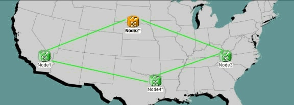
In order to remove nodes from a BLSR ring, you need to perform these steps:
-
Step 1: Delete any circuits that dropped at the node you want to remove.
-
Step 2: Identify, Delete and Re-create Pass Through Circuits That Change STS or VT.
Step 1: Delete Circuits That Drop at the Node You Want to Remove
You need to first identify and delete any circuits that drop at Node4.
 Caution: This procedure affects service. Be sure that you move all traffic that drops at this node before you delete any circuits.
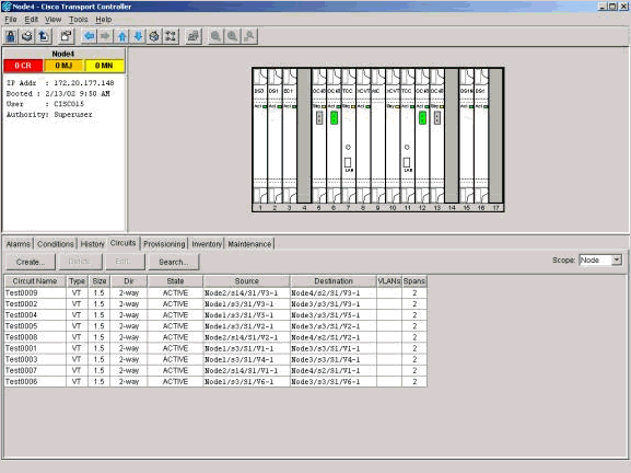
From the Shelf view of the node you want to remove, click the Circuits tab. Select Node from the Scope drop-down list to see only the circuits that pass through or drop at this node. Check the source and destination column to identify any circuits that contain the node you want to remove (Node4). In order to sort the Source or Destination columns, click on the column heading.
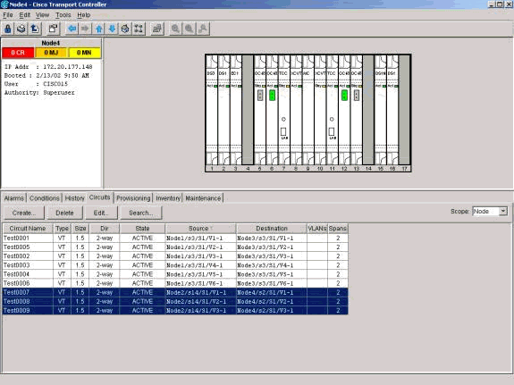
Complete these steps:
-
Click on each circuit to highlight it.
-
Click Delete.
-
Click Yes in the confirmation dialog box.
-
Click OK in the informational dialog box.
Note: In order to highlight multiple circuits for deletion, hold down the CTRL or SHIFT key while you click on each circuit.
Step 2: Identify, Delete and Re-create Pass Through Circuits That Change STS or VT
Note: This step is necessary only if you used CTC Release 2.x to create the circuits that pass through the node. If you provisioned this BLSR ring with Release 3.0 or later, proceed to Step 3.
You need to identify, delete and re-create any circuits that change STS or VT when the circuits pass through the node you want to remove.
 Caution: This procedure affects service. An outage occurs for the length of time you take to delete and re-create each circuit.
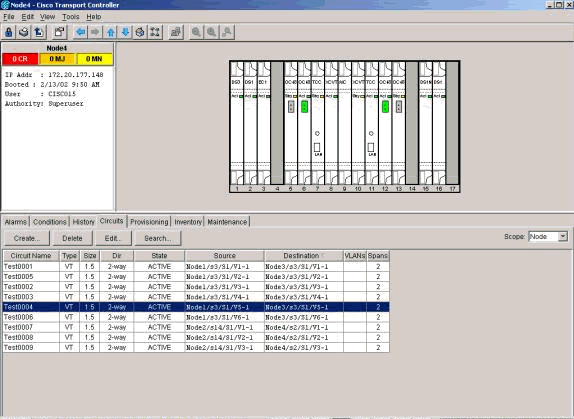
-
From the Shelf view of the node you want to remove, click the Circuits tab.
-
Select Node from the Scope drop-down list.
Since drop circuits for this node were identified and deleted in the previous step, this will show pass through circuits on this node.
-
One by one, highlight each circuit, and click Edit.
-
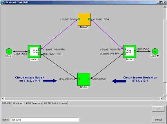
Check the Show Detailed Map check box.
You can view the STS and VT on which the circuit enters and leaves the node. If these do not match, document the circuit for deletion and re-creation.
In this case our circuit actually changes STS and VT through Node4. As you can see, it enters using STS2, VT1-1, and exits using STS3, VT2-1.
-
Repeat Step 4 for all circuits that show up in the node view. You are now ready to delete and re-create the circuits.
-
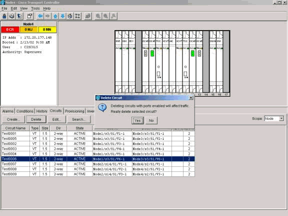
One by one, highlight the circuits you identified previously, and click Delete.
-
Click Yes to confirm the deletion.
-
After circuit deletion is complete, click OK in the informational dialog box.
-
Then click Create, and rebuild the circuit with the original parameters.
Step 3: Initiate Protection Switches
You now need to manually force traffic away from all spans that connect to Node4. Begin with the node that connects through the east port to Node4. Here, begin with Node3.
 Caution: A forced protection switch can cause service disruption if the rest of the ring does not run error-free. Check the PM statistics for the rest of the optics cards in the ring. Complete these steps:
-
Log into each shelf in the ring.
-
Click on a BLSR optics card.
-
Select the Performance tab.
-
Click Refresh.
You can expect to see zeros in all fields if the span is error-free.
Traffic is unprotected during a forced protection switch
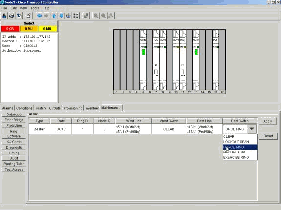
From the Shelf view of Node 3, click the Maintenance/Ring (Maintenance/BLSR in later software versions) tab. From the East Switch list choose Force Ring, and click Apply to force traffic away from the east span.
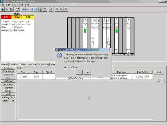
Select Yes in the confirmation dialog box.
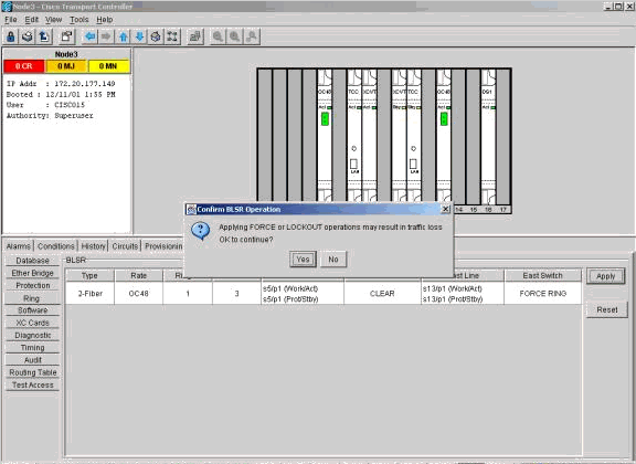
Select Yes again.
Now go to the Shelf view of the node that connects to the new node through the west port. Here, go to Node1.
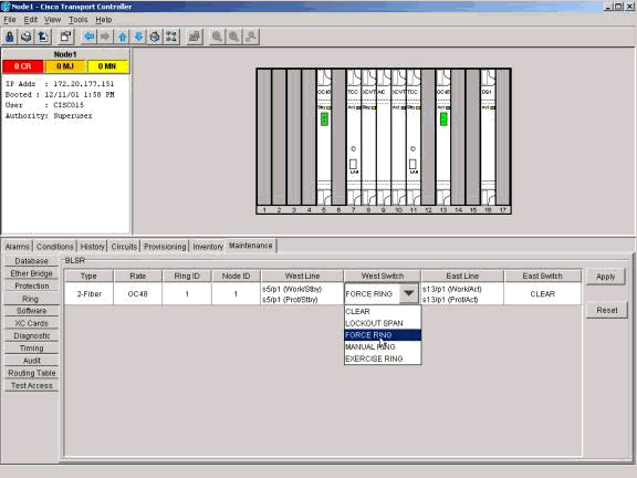
Go to the Maintenance/Ring (Maintenance/BLSR in later software versions) tab. From the West Switch list choose Force Ring and click Apply to force traffic away from the west span. Click Yes in the two confirmation dialog boxes.
Step 4: Remove the Node and Re-connect Adjacent Nodes
Note: If the node you want to remove is BITS timed, be sure to make appropriate adjustments to any line timed sites that use the node as a reference.
You can now safely remove fibers from Node4. Reconnect fibers to adjacent nodes. Here, connect Slot 5, Node1 to slot 13, Node3.

When you reconnect fibers to adjacent Nodes, first connect only Tx fibers, and check levels before you connect the Rx fibers. You can find Rx levels in the Card Reference section of the Cisco ONS 15454 Troubleshooting Guide, Release 5.0.
After you reconnect all fibers, open the Alarms tab of the newly connected nodes. Verify whether the span cards are free of alarms. Resolve any alarms before you proceed.
Step 5: Re-launch CTC
Next, you must close and re-launch CTC. Be sure not to launch CTC with the IP address of the node you just removed.
 Caution: The purpose of this step is to eliminate the removed node from the view in CTC. If you skip this step, and delete pass-through circuits from the removed node, the pass-through circuits can be deleted from the nodes still in the ring.
Step 6: Accept the Ring Map
Now accept the new Ring Map.
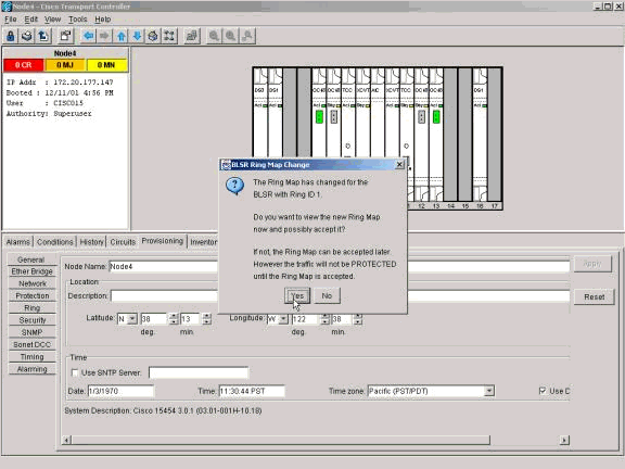
Wait for the BLSR Ring Map Change dialog box to appear. Click Yes to view the new Ring Map.
If the BLSR Ring Map Change dialog box does not appear:
-
Go to the Shelf view of either node adjacent to the removed node.
-
Select the Provisioning/Ring (Provisioning/BLSR in later software versions) tab.
-
Click in the Type field to highlight the ring information.
-
Click Ring Map.
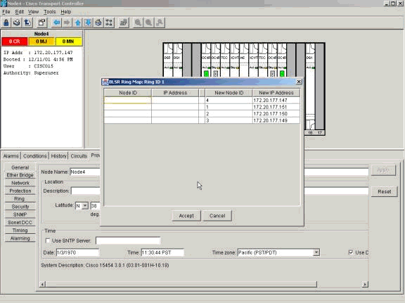
When you are sure that the IP addresses match the node IDs, click Accept.
Step 7: Release Protection Switches
The last step in the procedure is to release the protection switch you initiated in Step 3.
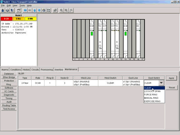
Log into the node with the protection switch on the east port. In the Maintenance/Ring (Maintenance/BLSR in later software versions) tab, select Clear from the East Switch List, and click Apply.
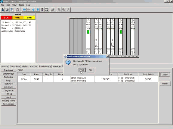
Click OK in the confirmation dialog box. Repeat this step for the node with a protection switch on the west port. Select Clear from the West Switch list.
Related Information
Contact Cisco
- Open a Support Case

- (Requires a Cisco Service Contract)


 Feedback