Upgrading XC and XCVT Cards to XC10G Cards
Available Languages
Contents
Introduction
This document explains how to upgrade a Cross Connect (XC) or Cross Connect Virtual Tributary (XCVT) card to a Cisco ONS 15454 XC10G card.
Note: The example in this document explains how to upgrade dual XC and XCVT cards with dual XC10G cards in the ONS 15454-SA-ANSI with live traffic.
Prerequisites
Requirements
Cisco recommends that you have knowledge of these topics:
-
A Path Unequipped alarm (UNEQ-P) alarm can occur when an XC card upgrade is in progress, if you have E100 or E1000 cards in your system. The alarm appears and clears within a few seconds.
-
The procedure is not service-affecting. However, the upgrade causes a switch less than 50 ms in duration. An XC or XCVT switch can cause a linear 1+1 optical carrier (OC-N) protection switch or a bidirectional line switch ring (BLSR) protection switch. Cisco recommends a maintenance window. However, a maintenance window is not absolutely necessary.
-
This procedure assumes that the XC or XCVT cards are installed in the 15454-SA-ANSI shelf (Release 3.1). You cannot perform this upgrade from shelves released earlier than 3.1, such as 15454-SA-NEBS3 or 15454-SA-NEBS3E shelves. The XC10G card requires the 15454-SA-ANSI.
-
You need to resolve any critical or major alarms before you begin this procedure. You can identify these alarms from the Alarms tab in Network view.
Components Used
The information in this document is based on these software and hardware versions:
-
Cisco ONS 15454 running Cisco Transport Controller (CTC) Release 3.1 or later.
-
Two XC or XCVT cards that are installed in the ONS 15454-SA-ANSI.
-
Two XC10G cards that are available for installation.
The information in this document was created from the devices in a specific lab environment. All of the devices used in this document started with a cleared (default) configuration. If your network is live, make sure that you understand the potential impact of any command.
Conventions
Refer to Cisco Technical Tips Conventions for more information on document conventions.
Upgrade XC or XCVT Cards to XC10G Cards
Complete these steps:
-
In order to avoid a protection switch, take these precautions before you perform an XC or XCVT switch:
BLSR
-
Ensure that the working span is active on both the local and remote nodes. In order to do so, select the Maintenance > Ring tab, and view the West or East line.

-
Ensure that the working span carries error-free traffic (in other words, ensure that no signal degrade [SD] or signal fail [SF] alarms are present).
-
Lock out the protection span before you initiate an XC or XCVT reset. Place a lockout on the East and West cards of the nodes adjacent to the XC or XCVT switch node.

1+1
In a 1+1 protection scheme, place a lockout on the protect card, and verify whether the traffic travels over the working span before you set the lockout. In order to do so, select the Maintenance > Protection tab, highlight the protect slot, and click Lock Out.
-
-
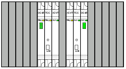
Determine the standby XC or XCVT card. The ACT/STBY LED of the standby XC or XCVT card is amber, while the ACT/STBY LED of the active XC or XCVT card is green.

Note: You can also place the cursor on the card graphic in CTC to view a dialog box. This display identifies the card as:
-
XC or XCVT: Active
-
XC or XCVT: Standby
-
-
Physically replace the standby XC or XCVT card on the ONS 15454 with an XC10G card. In order to do so, complete these steps:
-
Open the XC or XCVT card ejectors.
-
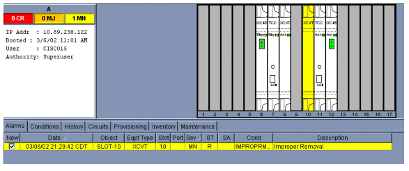
Slide the card out of the slot. This raises the IMPROPRMVL alarm, which clears when the standby XC 10G card reloads.

-
Open the ejectors on the XC10G card.
-
Slide the X10G card into the slot along the guide rails.
-
Close the ejectors.
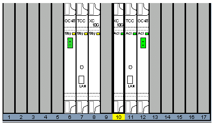
The fail LED above the ACT/STBY LED becomes red, blinks for several seconds, and turns off. The ACT/STBY LED turns amber, and remains lit.
-
-
Choose the Maintenance > XC Cards tabs in the Node view.

-
Choose Switch from the Cross Connect Cards menus.
-
Click Yes in the Confirm Switch dialog box.

Note: After the active XC or XCVT disengages, the standby slot or first XC10G card becomes active. This causes the ACT/STBY LED on the first XC10G card to change from amber to green.
Note: CTC shows XCVT cards until the second card fully loads. At this time, both cards in CTC show XC10G.
-
Physically remove the standby XC or XCVT card from the ONS 15454, and insert the second XC10G card into the empty XC or XCVT slot. In order to do so:
-
Open the XC or XCVT card ejectors.
-
Slide the card out of the slot.
-
Open the ejectors on the XC10G.
-
Slide the XC10G card into the slot along the guide rails.
-
Close the ejectors.
The upgrade is complete when the second XC10G card boots up and becomes the standby XC10G.

-
-
Release the protection lockout.
The procedure is now complete.
Related Information
Contact Cisco
- Open a Support Case

- (Requires a Cisco Service Contract)


 Feedback