Replacing the Alarm Interface Panel on a Cisco ONS 15454
Available Languages
Contents
Introduction
This document describes how to change the alarm interface panel (AIP) board on a Cisco ONS 15454 shelf.
 Caution: Multi-card (stitched) provisioned Ethernet circuits that terminate on E-series cards are not repaired and those particular circuits need to be deleted and created. This applies to all software releases from 2.2.0 up to 4.6 (at the time of editing this procedure).
Prerequisites
Requirements
There are no specific prerequisites for this document.
Components Used
This document is not restricted to specific software and hardware versions.
Background
The AIP stores the MAC address of the 15454 node. This address serves as reference for all circuits. If you change the AIP, it means that you change the MAC address of that node, and this new address must be updated in the circuit list database.
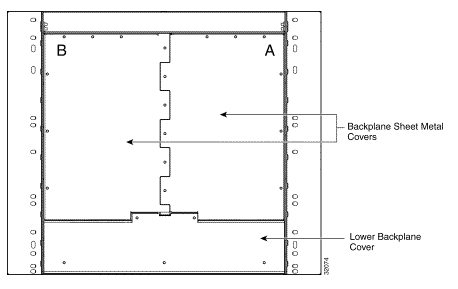
The AIP board is located under lower backplane cover, as shown here:

Before you carry out this procedure:
-
Be sure to execute this procedure during a maintenance window, as it might be service-affecting.
-
Ensure that you have a database backup and that the circuit list is saved on your computer.
Conventions
Refer to the Cisco Technical Tips Conventions for more information on document conventions.
Replace the Alarm Interface Panel
Complete these steps:
-
Obtain the old MAC address of the node in question (this may be zero).
Note: The MAC address appears on the node-level Provisioning > Network tab.
-
Change the AIP card on that node.
The lower section of the ONS 15454 backplane is covered by a clear plastic protector, which is held in place by five 6-32 x 1/2 inch screws. Complete these steps to remove this:
-
Remove the clear plastic cover from the AIP.
-
Unscrew the two screws that hold the AIP in place.
-
Grip the panel on each side.
-
Gently remove the panel from the backplane.
-
Remove the fan-tray assembly power cable.
-
Attach the fan-tray assembly power cable to the new AIP.
-
Place the new AIP on the backplane by plugging the panel into the backplane using the Deutsche Industrie-Norm (DIN) connector.
-
Replace the screws that secure the pane to the backplane.
-
-
Reset both Timing, Communication, and Control Plus (TCC+) cards one at a time.
Note: Wait until first TCC+ card is fully turned back in service with no alarms, and then reset the second TCC+ card.
-
Exit and restart Cisco Transport Controller (CTC).
-
Wait until the circuit discovery is complete, and all circuits are "active", except for those that need repair.
Note: If you have not completed all these steps, the repair does not succeed.
-
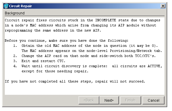
Repair the circuits. In the CTC menu, select Tools > Repair Circuits. This window displays:

-
Click Next.
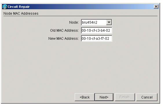
Choose the node where you have replaced the AIP card.
-
Enter the old MAC address (from step 1) and the new MAC address (you can see it in Node view, Provisioning > Network) of the new AIP board.
Here is an example:

-
Click Next.
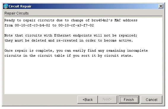
This window displays:

-
Click Finish to complete the procedure.
Verify
Check the circuit list to verify the result. All items should have "active" status.
Note: It might be necessary to wait awhile before you check this. This depends on how many nodes are in the network.
Troubleshoot
If anything goes wrong at any point during this process, contact the Cisco Technical Assistance Center (TAC) for further assistance.
Related Information
Contact Cisco
- Open a Support Case

- (Requires a Cisco Service Contract)


 Feedback