Creating VTT Circuits and VTs for the Cisco ONS 15454
Available Languages
Contents
Introduction
This document explains how to create virtual tributary (VT) for both unidirectional path switched ring (UPSR) and bidirectional line switched ring (BLSR) topologies that run Cisco ONS 15454 Release 3.10 software (Release 3.10-001K-17.01).
Refer to Understanding the 15454 XC and XC-VT Switching Matrix for an explanation and examples of the VT matrix capabilities.
Note: The Cisco ONS 15454 Troubleshooting and Maintenance Guide contains detailed specifications of the cross connect (XC), cross connect virtual tributary (XCVT), and XC10G cards.
Prerequisites
Requirements
You can provision circuits before cards are installed. The ONS 15454 allows you to provision slots and circuits before you install the traffic cards. Right-click it and choose a card from the shortcut menu in order to provision an empty slot. But, circuits do not carry traffic until you install the cards and put their ports into service. Refer to the instructions on how to install optical, electrical, and Ethernet cards and enabling ports in the Card Provisioning document for procedures.
After cards are installed, the ports are out of service. You must place the ports in service before the circuits carry traffic. Once cards are installed, and their ports are in service, the circuits carry traffic as soon as the signal is received.
Components Used
The information in this document is based on Cisco ONS 15454 Release 3.10 software (Release 3.10-001K-17.01).
The information presented in this document was created from devices in a specific lab environment. All of the devices used in this document started with a cleared (default) configuration. If you are working in a live network, ensure that you understand the potential impact of any command before using it.
Conventions
Refer to Cisco Technical Tips Conventions for more information on document conventions.
Create VT and VTT Tunnels
Note: If you are concerned about consistent bandwidth management, it is recommended you create two VTT tunnels manually in order to allow the tunnels to transverse each node and maximize the VT matrix in each node.
Step 1: UPSR Tunnels Scenario - Four-Node UPSR Ring
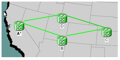
In this example, you start with a four-node UPSR with a tunnel created from nodes B to D.
-
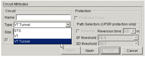
Under Circuits, create and name your circuit and then choose Type. In this case, it is a VT tunnel. Click Next.
-
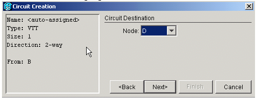
Choose the source node and then the destination node.
In this example, you can see that the VTT from source node B goes to destination node D.
-
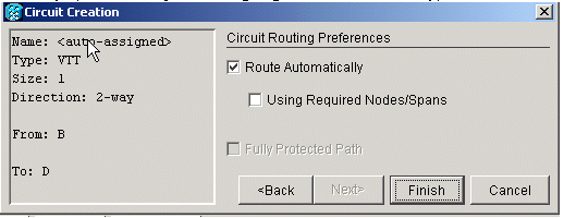
At this point you have the option to either route automatically or uncheck the box in order to route manually. In this example, you route automatically. Click Finish in order to continue.
-
When the circuit has been created you can see it in the circuits list.
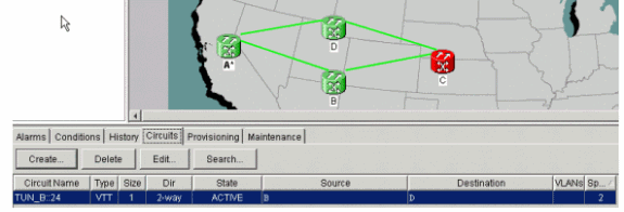
-
At this point, you also get a UNEQ-P alarm on your optical carrier (OC) cards.
In this example, you use OC48 cards. These alarms clear once a live signal is on the tunnel.
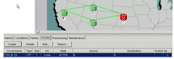
-
Right-click on the span lines in your network view, and choose Circuits in order to see the tunnel and on which Synchronous Transport Signal (STS) it rides.
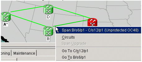
In this case, it is STS 1.

-
If you highlight the VTT in the circuits list, then choose Edit and check detailed map, you can see precisely what the circuit path is.
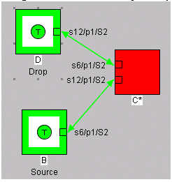
Step 2: Create the Second Tunnel
The second tunnel is created manually. The second tunnel needs to be created on the same STS, around the opposite side of the ring. The only way to do this is to route it manually. If you allow the system to route your second tunnel automatically, it puts it on the next sequential STS. If that happens and you create your VTs automatically, then you get working and protection paths on different STSs.
Create the second tunnel automatically in order to see this in action. Once you create it, you can see it in the circuits list.

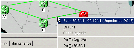
Right-click on the span line and choose Circuits in order to see on which STS the second tunnel rides.
Step 3: Create Tunnels Manually in UPSR
Complete the steps in this procedure:
-
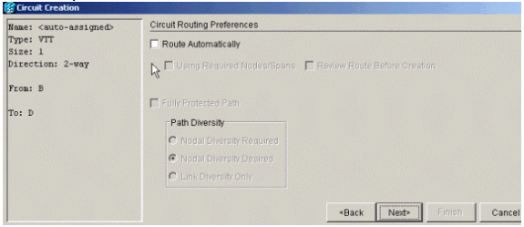
Repeat the instructions in step 2, but this time uncheck the Route Automatically box and click Next in order to create tunnels manually.
-
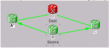
Choose the source node in order to change the span lines to arrows.
-
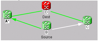
Once you choose a direction, the line turns white. Click on Add Span.
-
Once you add the span, it turns blue and designates the next span of direction.
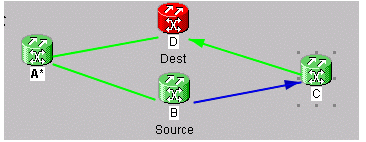
-
Click on the next span and add it.
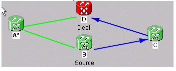
-
Click Finish.
At this point, you see that the tunnel is added to the circuit list. Right-click on the span line in network view and check the STS the tunnel is in. Choose the STS before you add the span in order to proceed to the protect side tunnel and ensure that it is created on the same STS around the opposite side ring. This way you are sure to get the same STS in order to handle each tunnel.
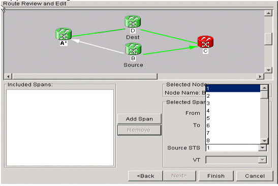
-
You are now ready to create your VT1.5 in order to fill up all 28 VTs in the tunnel. Go to circuits and create a VT.
Note: If your tunnels are on different STSs then you get one path in one tunnel and the second path continues on the same STS. But, this might not be in a tunnel, which defeats the purpose of the use of a tunnel in order to maximize bandwidth
Note: Refer to the Circuits and Tunnels chapter of the Cisco ONS 15454 Installation and Operations Guide.
Step 4: Create VT Circuits Automatically
Complete the steps in this procedure in order to create VT circuits automatically.
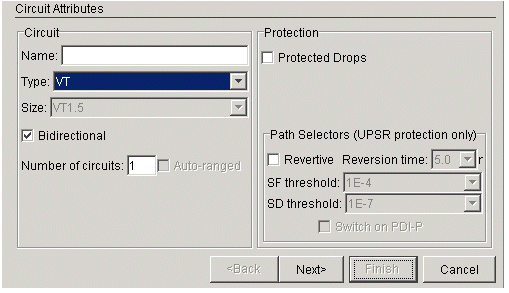
-
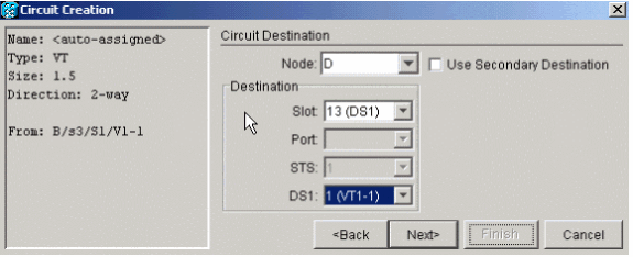
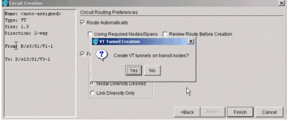
You can see here that you go from B/s3/S1/V1-1 to D/s13/S1/V1-1. Once you have a source and destination, click Next. Double check in order to ensure the circuit path is correct and click Finish.
-
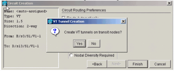
At this point a message appears and asks if you want to create VT tunnels on transit nodes. Click No in order to make the VT go into an existing tunnel.
-
Once the circuit has been created, right-click on the span line and see in which tunnel the VT rides.
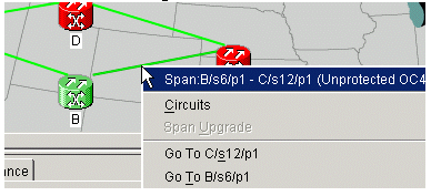
You see in this example that VTC_B::26 is in TUN_B::24. STS1.

-
When you look at the other direction of the span line you can also check to see which tunnel and which STS are used.
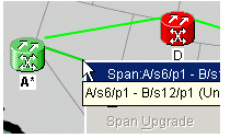
You see in this example that VTC_B::26 is also on STS1.

Step 5: Alternative Scenario
If you chose Yes in step 2 when you got this message, this is what can happen.
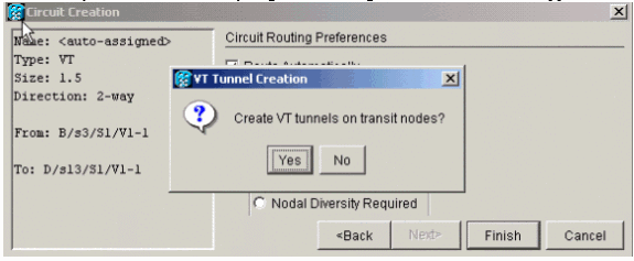
The system automatically creates a new VTT and places VT1.5 into that particular tunnel.

If you right-click on the spans, you can see where the VT is placed.
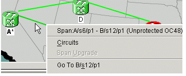
In this case a new tunnel TUN_B::28 is created, and VTC_B::29 is placed inside the tunnel.
Note: Do not click on Yes in order to create a new tunnel, because there is no need for it until you fill up the two tunnels that exist.

Step 6: Create VT Circuits Manually
You can also create VTs manually, place them inside the tunnels, and choose the STSs on which you want the protect and working to be.
-
Choose Circuits > Create > VT in order to start this procedure, then choose your source and destination along with ports, and uncheck the Route Automatically box.
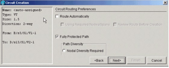
-
A message appears and asks if you want to create Transit VTT. Click No and be prepared to choose tunnels.
-
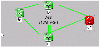
Choose the source node and click on it in order to turn the available span lines into arrows.
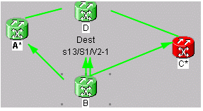
-
The two arrows that point from node B to D represent your tunnels. Choose one of the arrows. This is your working tunnel path. Click Add Span.
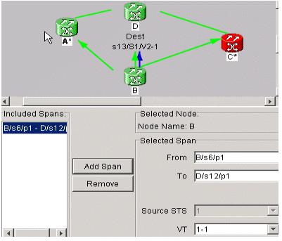
-
Choose the other arrow. This is your protect path of the VT.
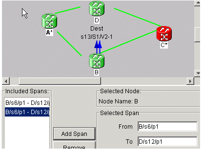
Once the circuit is created it shows up in the circuit list as VTC_.

-
Right-click on the span in order to get circuit information in order to verify that you chose the correct STS.
Note: In order to groom your VTs and VTTs in a UPSR topology, the best and most recommended way is to create your VTT manually on the same STS and then place your VTs inside the tunnels. You can create them automatically or manually.
Step 7: Create VTT in BLSR
When you create a VTT in a BLSR configuration, it is only necessary to create one tunnel because the protect path is inherited. You can also use the route automatically feature with BLSR or manually route.
In this example you create a tunnel from B to D automatically.
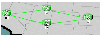
-
Choose Circuits > Create and choose VT tunnel, then click on Next.
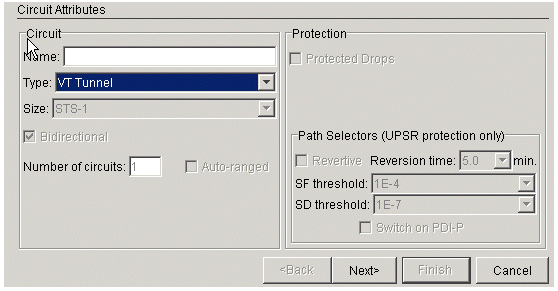
-
In BLSR, you can route the tunnels automatically because the system only creates circuits on STSs that are fully available throughout the nodes you go through. Click Next.
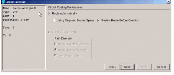
-
If you choose Review Route Before Creation, you get a visual of which path the circuit plans to take, and you can modify it at this point.
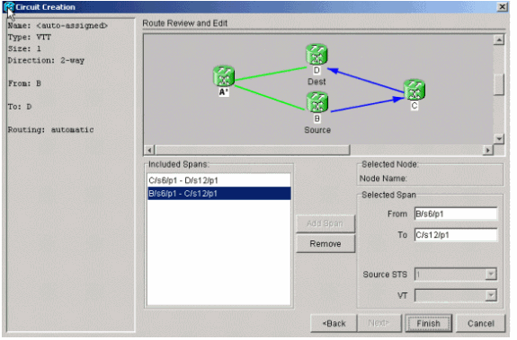
-
Click Finish in order to add the circuit to the circuit list.

-
Right-click on the span in Network view in order to display the circuits so you can verify that the tunnel is there.
Note: If you choose to create your tunnel manually, the only difference is to uncheck the Route Automatically box, and proceed as in the previous steps.

Step 8: Add the VT to Tunnels Automatically
Complete these steps in order to automatically add your VT to the tunnels.
-
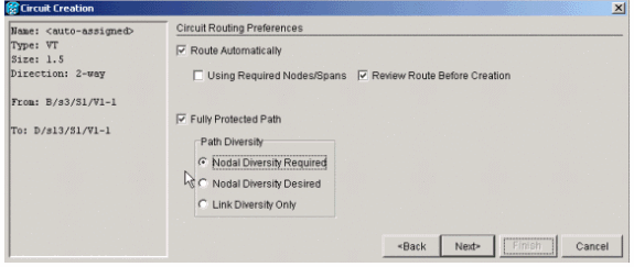
Under Circuits > Create, choose VT and choose the slot and port of your source and destination nodes. In this example, you go from B/s3/S1/V1-1 to D/s13/S1/V1-1. Click Next.
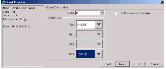
-
Click Finish if you are ready to proceed with the route automatically.
-
Check the circuit list as well as the spans in Network view in order to see where the circuit is.
Note: If you choose Route Automatically, it goes to place the VT in the first sequential STS that has room for it. Once it fills up the STS, the system moves on to the next STS tunnel that has enough room for VTs.
-
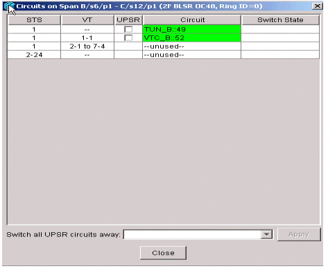
Right-click on the Network view span line in order to see where the circuit is.
-
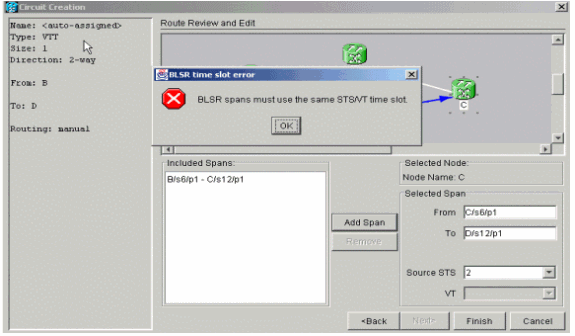
Create the VT manually in order to place the VT inside a tunnel and choose the spans of your choice.
If you choose a span that is not on the same timeslot you get an error message.
Step 9: Other Methods to Create VTTs
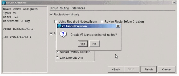
Create a VT first in order to also create VTT.
-
When the system asks you if you want it to create a VTT on transit nodes, click Yes in order to create a VTT and place the VT inside it.
-
Look at the circuits list in order to verify your circuits.

-
Alternatively, right-click on the span line in network view and look at the circuits.

-
If you click No at this point, it adds the VT without a tunnel.
Related Information
Revision History
| Revision | Publish Date | Comments |
|---|---|---|
1.0 |
03-Oct-2006 |
Initial Release |
Contact Cisco
- Open a Support Case

- (Requires a Cisco Service Contract)


 Feedback