Creating a Circuit for Monitoring the Ring
Available Languages
Contents
Introduction
This document presents a lab setup that shows a simple procedure to create a bidirectional circuit to monitor the ring. The circuit starts on the transmit leg of a port on either a DS1 or DS3 board and traverses the ring. It is physically looped by a second port on the same board back to the return leg on its original port. The procedure in this document is used for circuits on both bidirectional line switched rings (BLSRs) and unidirectional path switched rings (UPSRs).
Note: Monitoring circuits is done only on bidirectional built circuits. Monitoring builds a one-way circuit path to the test set from the DS1/DS3/EC1 card. Create a drop circuit such as broadcast video to monitor a unidirectional (one-way circuit).
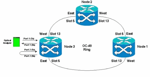
The topology used in this document is shown here. In the topology, the end points of the monitoring circuit are on the same board on the same node. This procedure works equally well if the end points are on separate boards on separate nodes. This procedure is performed on various topology types such as UPSR, BLSR, and Linear. Monitor circuits are not used on EtherSwitch-type circuits.
Prerequisites
Requirements
Cisco recommends that you have knowledge of these topics:
-
Cisco ONS 15454 ring/topology configurations.
-
Use of the ONS 15454 Cisco Transport Controller (CTC) GUI.
-
Use of a Tberd DLI or similar test set.
-
Optical analyzer for dense wavelength division multiplexing (DWDM) analysis only (optical spectrum analyzer (OSA) is not used).
Components Used
The information in this document is suitable for all Cisco ONS 15454 Software Versions 2.x and later. However, it is based on this software version :
-
Cisco ONS 15454 Software Versions 3.0.3, 3.1.x, 3.2.x, 3.3.x and 3.4.x
The information in this document was created from the devices in a specific lab environment. All of the devices used in this document started with a cleared (default) configuration. If your network is live, make sure that you understand the potential impact of any command.
Conventions
Refer to Cisco Technical Tips Conventions for more information on document conventions.
Connect, Test, and Create the Monitoring Circuit
In these procedures, the test set is connected to Port 2. Port 1 is live traffic connected to the Class 5 Switch. A local one-way (unidirectional) circuit is temporarily created between the two ports (Port 1 live traffic) to (Port 2 Monitor Circuit) to test the connectivity and signal performance. The circuit traverses the ring. The monitoring circuit is then created to Port 2. A test set is connected directly between the receive input of the test set and the monitor or transmit jack of the DSX panel. Ensure the test set is set up for proper coding and format to match the live traffic on Port 1. Refer to this example taken from the Cisco ONS 15454 Reference Guide, Release 3.4.
"You can set up secondary circuits to monitor traffic on primary bidirectional circuits. This figure shows an example of a monitor circuit. At Node 1, a VT1.5 is dropped from Port 1 of an EC1-12 card. To monitor the VT1.5 traffic, test equipment is plugged into Port 2 of the EC1-12 card. A monitor circuit to Port 2 is provisioned in CTC. Circuit monitors are one-way. The monitor circuit in this figure is used to monitor VT1.5 traffic received by Port 1 of the EC1-12 card."

Note: Monitor circuits cannot be used with EtherSwitch circuits.
On Node 1, the monitoring circuit originates on the transmit leg on Port 2 to the receiving side of the test set (DS1-14/DS3/EC1) card in Slot 2. The live bidirectional signal traverses the ring. It passes through Node 2 and arrives on the receive leg on Port 2 on the DS1-14/DS3/EC1 card. The circuit is physically looped or is software looped at the far end Node 2 on the Port 2 DS1/DS3/EC1 card. The signal then loops back, returns, and traverses the ring in the opposite direction to Node 1.
Connect the Bit Error Rate Test Set
Complete these steps to connect the analyzer on Port 2 and to physically loop Port 1 on the DS1-14 card in Slot 2 at the far end Node 2.
-
On Node 1, the analyzer is connected to Port 2 on the DS1-14 card in Slot 2.
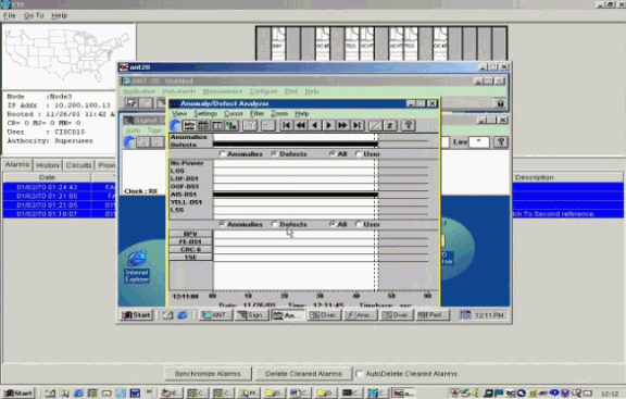
After the analyzer is connected to Port 2, you see an Alarm Indication Signal (AIS)-DS1 condition on Port 1 without loopback inserted at Node 1.
Note: AIS is an all-ones output to the test set.
-
On Node 1, physically loop Port 2 on the DS1-14 card in Slot 2.
Test the Connected Devices
Test the connections on Ports 1 and 2 on the DS1-14 card by creating a temporary test circuit between them. The name of the temporary circuit is TEST1.
-
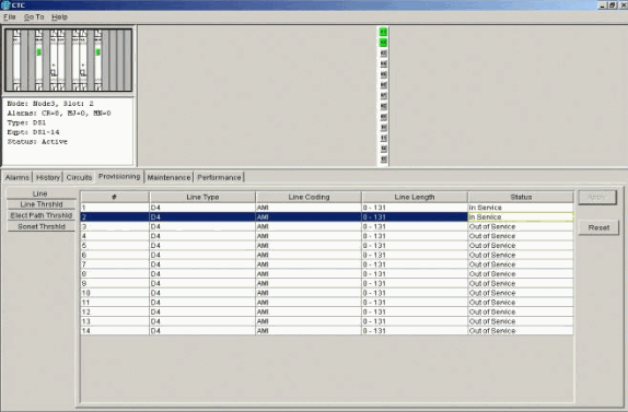
Activate Ports 1 and 2 by placing these ports In-Service on the DS1-14 card.
-
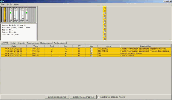
After Ports 1 and 2 on the DS1-14 card are activated, you see an AIS-DS1 condition.
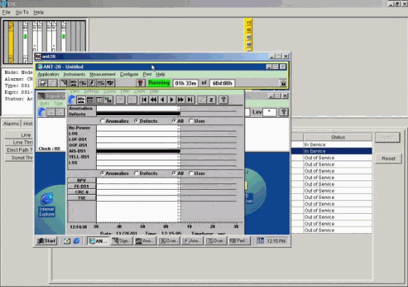
An AIS alarm is generated when Ports 1 and 2 on the DS1-14 card are in-service.
-
Verify the connections on Node 1, Slot 2, Port 1 to Node 2, Slot 2, Port 1 and a monitor circuit from Node 1, Port 2 (one-way circuit to the test set) on the DS1-14 card.
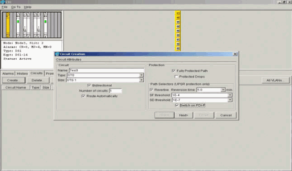
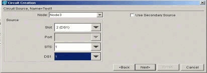
The source (Node 1) for the test circuit is Port 1 on the DS1-14 card. Select a circuit type and DS#.
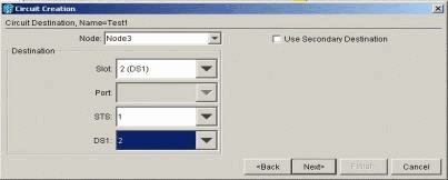
The destination (Node 1) for the test circuit is Port 2 on the DS1-14 card. Select a circuit type and DS#.
Click Finish to confirm the temporary test circuit creation. A unidirectional circuit is built to your test set monitoring jack (receive jack).
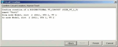
-
Verify that the AIS alarm generated in step 2 is now clear.
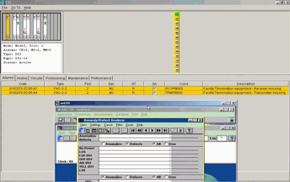
-
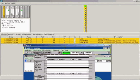
When you open the physical loop on Port 2, it causes a Loss of Signal (LOS) alarm, as shown here:
When you close the physical loop on Port 2, it clears the AIS alarm.
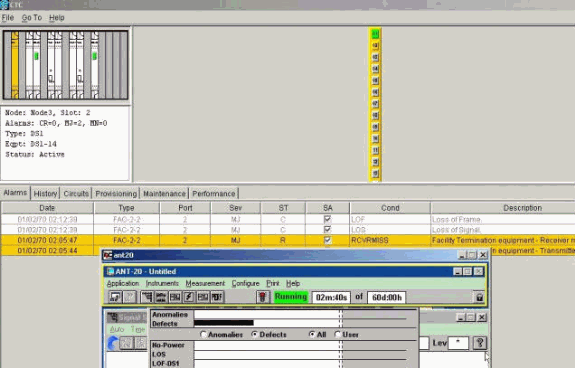
-
You can now delete the temporary test circuit.
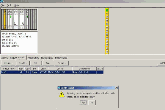
-
Before you build the monitoring circuit around the ring, check the list of alarms to make sure that there are no error conditions present.
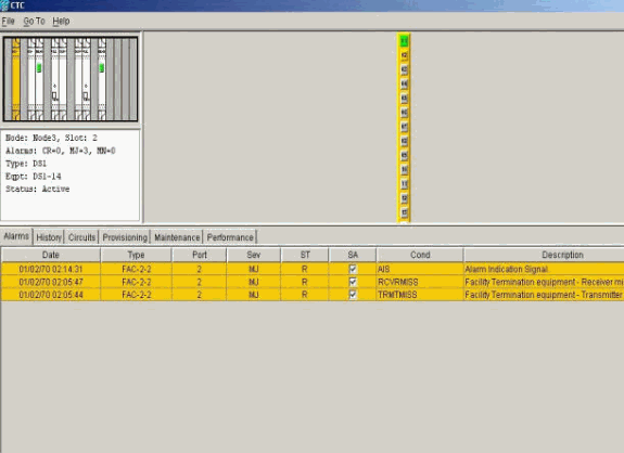
Create the Monitoring Circuit Example Using Three Nodes
The monitoring circuit uses four manually configured Cross-Connects (XC/XCVTs). Two XCs on Node 1 go from Ports 1 and 2 in the DS1-14 card in Slot 2, to the Optical Carrier-48 (OC-48) cards in Slots 5 and 13. XC/XCVTs in Nodes 2 and 3 then go from OC-48 cards in Slots 5 and 13. The monitoring circuit is called TEST2. The topology here shows the outbound and return path the monitoring circuit takes around the ring.
Note: The monitoring circuit (one way circuit) is not automatically created. It is manually configured.
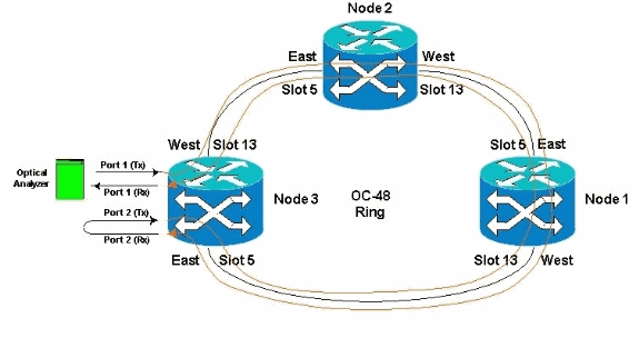
-
Start to manually configure the monitoring circuit in Node 3.
The first XC goes from Port 1 of the DS1-14 card in Slot 2 to Port 1 of the OC-48 card in slot 5. The exact path is Slot 2, Port 1, STS 1, VT 1 to Slot 5, Port 1, STS 1, VT 1.
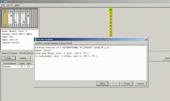
-
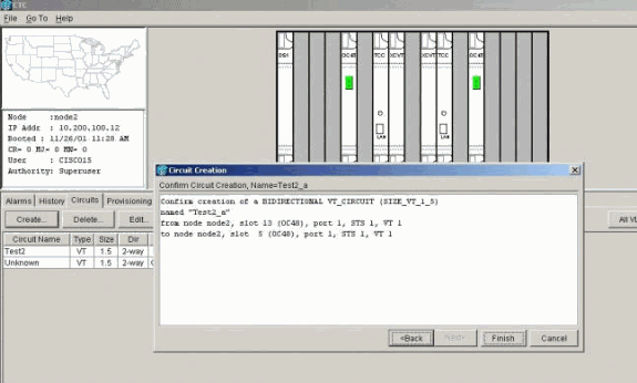
Manually configure the second XC on Node 2.
The XC goes from Port 1 on the OC-48 card in Slot 5 to Port 1 on the OC-48 card in Slot 13. The exact path is Slot 5, Port 1, STS 1, VT 1 to Slot 13, Port 1, STS 1, VT 1.
-
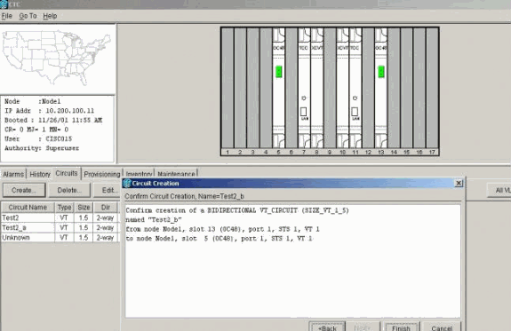
Manually configure the third XC on Node 1.
The XC goes from Port 1 on the OC-48 card in Slot 5 to Port 1 on the OC-48 card in Slot 13. The exact path is Slot 5, Port 1, STS 1, VT 1 to Slot 13, Port 1, STS 1, VT 1.
-
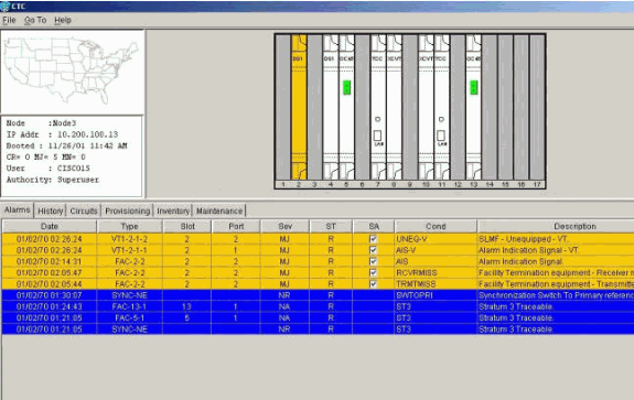
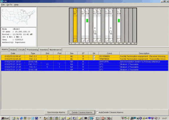
While you create the XCs, some alarms are generated, such as those shown here. Ignore alarms LOS and AIS-VT.
-
Manually configure the final XC on Node 3.
The XC goes from Port 2 on the DS1-14 card in Slot 2 to Port 1 on the OC-48 card in Slot 13. The exact path is Slot 2, Port 2, STS 1, VT 2 to Slot 13, Port 1, STS 1, VT 1.
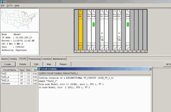
After the monitoring circuit is created, loopbacks in place, and ports placed In-Service, these alarms illustrated in step 4 clear.
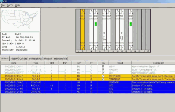
Alarms generated on the test set also clear.
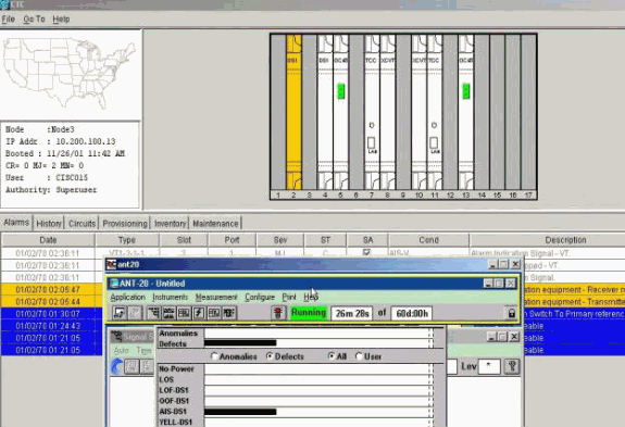
-
Perform a test to verify that the monitoring circuit is complete.
On Node 3, removal of the physical loop on Port 2 on the DS1-14 card in Slot 2 causes an AIS alarm to appear.
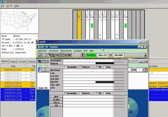
-
You can see the monitoring circuits from the Network View.
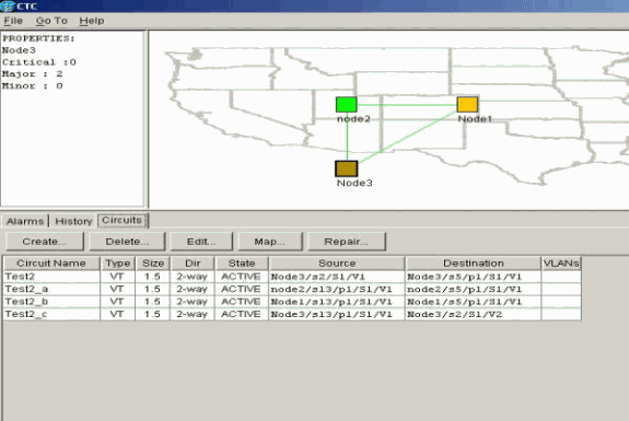
All alarms are cleared.
The procedure to configure the monitoring circuit is now complete. The circuit is ready to be used to monitor the ring.
Related Information
Revision History
| Revision | Publish Date | Comments |
|---|---|---|
1.0 |
09-Jan-2006 |
Initial Release |
Contact Cisco
- Open a Support Case

- (Requires a Cisco Service Contract)


 Feedback