Understanding MAC Addressing with SRP
Available Languages
Contents
Introduction
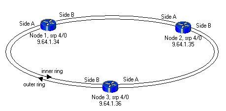
Spatial Reuse Protocol (SRP) is a Cisco-developed MAC-layer protocol used in ring configurations. An SRP ring consists of two counter-rotating fibers, known as the outer and inner ring. Both are concurrently used to carry data and control packets. Control packets, such as keep-alives, protection switching, and bandwidth control propagation, propagate in the opposite direction from the corresponding data packets to ensure that the data takes the shortest path to its destination. A dual fiber-optic ring provides a high level of packet survivability. In the event of a failed node or a fiber cut, the data transmits over the alternate ring. Topology packets transmit on the outer ring except when some node on the ring is in a wrap condition.
This document explains SRP interface relations, which is the most frequent reason for misinterpretation of MAC addresses.
Prerequisites
Requirements
There are no specific requirements for this document.
Components Used
This document is not restricted to specific software and hardware versions.
The information in this document was created from the devices in a specific lab environment. All of the devices used in this document started with a cleared (default) configuration. If your network is live, make sure that you understand the potential impact of any command.
Conventions
Refer to Cisco Technical Tips Conventions for more information on document conventions.
One MAC Address
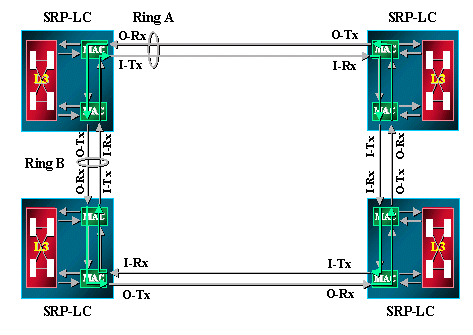
One SRP interface on any SRP line card (LC) has two MACs, but only one MAC address. These two MACs actually form one SRP interface that consists of an A side and a B side.
See this show interface sample output:
-
A side: Outer Ring Rx, Inner Ring Tx
-
B side. Outer Ring Tx, Inner Ring Rx

For example:
Node2#show interface srp 4/0
SRP4/0 is up, line protocol is up
  Hardware is SRP over SONET, address is 0000.4142.8799 (bia 0000.4142.8799)
  Internet address is 9.64.1.35/24
  MTU 4470 bytes, BW 622000 Kbit, DLY 100 usec, rely 255/255, load 1/255
  Encapsulation SRP,
  Side A: loopback not set
  Side B: loopback not set
     3 nodes on the ring   MAC passthrough not set
     Side A: not wrapped   IPS local: SF	 IPS remote: IDLE
     Side B:     wrapped   IPS local: IDLE	 IPS remote: IDLE
  Last input 00:00:00, output 00:00:00, output hang never
  Last clearing of "show interface" counters never
  Queueing strategy: fifo
  Output queue 0/40, 0 drops; input queue 0/75, 0 drops
  5 minute input rate 0 bits/sec, 1 packets/sec
  5 minute output rate 0 bits/sec, 0 packets/sec
     356572 packets input, 7674965 bytes, 0 no buffer
     Received 0 broadcasts, 0 runts, 0 giants, 0 throttles
     112289 input errors, 54938 CRC, 0 frame, 0 overrun, 0 ignored, 57351 abort
     1943503 packets output, 67532068 bytes, 0 underruns
     0 output errors, 0 collisions, 1 interface resets
     0 output buffer failures, 0 output buffers swapped out
Program MAC Addresses for SRP Interfaces
In the show interface output, the MAC address is 0000.4142.8799. It is the same as the built-in MAC address (BIA) for this SRP interface. You can also program it to have a customized value like the MAC address, which is listed in the show srp topology output.
For example:
Node2#configure terminal
Node2(config)#interface srp 4/0
Node2(config-if)#mac-address 0.0.2

Node2#show interface srp 4/0h
SRP4/0 is up, line protocol is up
  Hardware is SRP over SONET, address is 0000.0000.0002 (bia 0000.4142.8799)
  Internet address is 9.64.1.35/24
  MTU 4470 bytes, BW 622000 Kbit, DLY 100 usec, rely 255/255, load 1/255
  Encapsulation SRP,
  Side A: loopback not set
  Side B: loopback not set
     3 nodes on the ring   MAC passthrough not set
     Side A: not wrapped   IPS local: SF	 IPS remote: IDLE
     Side B:     wrapped   IPS local: IDLE	 IPS remote: IDLE
  Last input 00:00:00, output 00:00:00, output hang never
  Last clearing of "show interface" counters never
  Queueing strategy: fifo
You can program the MAC address for the SRP interface to be the one listed in the show srp topology output.
Node2#show srp topology

 Topology Map for Interface SRP4/0
  Topology pkt. sent every 5 sec. (next pkt. after 0 sec.)
  Last received topology pkt. 00:00:04
  Last topology change was 00:00:09 ago.
  Nodes on the ring: 3
  Hops (outer ring)      MAC       IP Address      Wrapped SRR   Name
      0             0000.0000.0002 9.64.1.35         Yes     -   Node2
      1             0007.0dec.a300 9.64.1.36         No      -   Node3
      2             0010.f60d.7a00 9.64.1.34         Yes     -   Node1
One-Port OC48 and OC192 SRP Boards
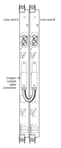
Any SRP interface on an SRP LC has two MACs but only one MAC address. For one-port OC48 and the OC192 SRP card, it is the same. The only difference is that sides A and B of the interface are seated in the two neighboring slots. There are two slots equipped for one single SRP interface. Side A is always the slot with the lower number and side B is the slot with the higher number.

How Data Sending is Managed
Data always takes the shortest path to its destination. The node that sources traffic is aware of the shortest path to the destination due to SRP topology information. The source node sends traffic over the shorter side since the destination has one unique MAC address for sides A and B of the interface.
The diagram and the show topology and show arp command outputs show an example of an SRP ring.

Node1#show srp topology
 Topology Map for Interface SRP4/0
  Topology pkt. sent every 5 sec. (next pkt. after 2 sec.)
  Last received topology pkt. 00:00:02
  Last topology change was 00:07:27 ago.
  Nodes on the ring: 3
  Hops (outer ring)      MAC       IP Address      Wrapped SRR   Name
      0             0010.f60d.7a00 9.64.1.34         No      -   Node1
      1             0000.4142.8799 9.64.1.35         No      -   Node2
      2             0007.0dec.a300 9.64.1.36         No      -   Node3

Node1#show arp
Protocol  Address          Age (min)  Hardware Addr   Type   Interface
Internet  9.64.1.34               -   0010.f60d.7a00  SRP-B  SRP4/0
Internet  9.64.1.35               4   0000.4142.8799  SRP-B  SRP4/0
Internet  9.64.1.36               4   0007.0dec.a300  SRP-A  SRP4/0
Internet  10.48.70.19           145   0060.4741.0432  ARPA   Ethernet0
Internet  10.48.70.12           145   0000.0c4a.dcb8  ARPA   Ethernet0
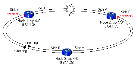
If there is a fiber cut between Node1 and Node2 in the ring, as this example shows, the show topology and show arp output looks like this:

Node1#show srp topology

 Topology Map for Interface SRP4/0
  Topology pkt. sent every 5 sec. (next pkt. after 2 sec.)
  Last received topology pkt. 00:00:02
  Last topology change was 00:02:02 ago.
  Nodes on the ring: 3
  Hops (outer ring)      MAC       IP Address      Wrapped SRR   Name
      0             0010.f60d.7a00 9.64.1.34         Yes     -   Node1
      1             0000.4142.8799 9.64.1.35         Yes     -   Node2
      2             0007.0dec.a300 9.64.1.36         No      -   Node3

Node1#show arp
Protocol  Address          Age (min)  Hardware Addr   Type   Interface
Internet  9.64.1.34               -   0010.f60d.7a00  SRP-B  SRP4/0
Internet  9.64.1.35               9   0000.4142.8799  SRP-A  SRP4/0
Internet  9.64.1.36              10   0007.0dec.a300  SRP-A  SRP4/0
Internet  10.48.70.19           151   0060.4741.0432  ARPA   Ethernet0
Internet  10.48.70.12           151   0000.0c4a.dcb8  ARPA   Ethernet0
This example shows that the source node chooses the shorter route to the destination and sends over either the A side or the B side of the interface in accordance with the show srp topology information.
Conclusion
For each SRP interface, there are two Tx and Rx pairs. One pair forms the A side and the other pair forms the B side of the interface. This interface has one unique MAC address even though it has two MACs that cover each Tx and Rx pair.
Related Information
Contact Cisco
- Open a Support Case

- (Requires a Cisco Service Contract)
 Feedback