Understanding SRP Ring Topology
Available Languages
Contents
Introduction
This document uses the show srp topology command output data from the router and examples to explain Spatial Reuse Protocol (SRP) topology in a concise manner.
The SRP is a Cisco-developed MAC-layer protocol used in ring configuration. An SRP ring consists of two counter-rotating fibers, known as outer and inner rings, both concurrently used to carry data and control packets. Control packets (keepalives, protection switching, and bandwidth control propagation) propagate in the opposite direction from the corresponding data packets. This ensures that the data takes the shortest path to its destination. The use of a dual fiber-optic ring provides a high level of packet survivability. In the event of a failed node or a fiber cut, data is transmitted over the alternate ring. Topology packets are transmitted on the outer ring (except when a node on the ring is in the wrapped condition).
Prerequisites
Requirements
There are no specific requirements for this document.
Components Used
This document is not restricted to specific software and hardware versions.
Conventions
Refer to the Cisco Technical Tips Conventions for more information on document conventions.
Understand SRP Topology
There are more than two possible ways to understand SRP ring topology. The most frequently used method is to obtain output from the show controllers command for the SRP interface. When you have up to three nodes per ring, it is viable to discover the topology in this way. For an SRP ring with a higher number of nodes, this method is very time-consuming and, as there is a lot of data to be checked, the possibility for error is high.
Node2#show controller srp 4/0
SRP4/0 - Side A (Outer RX, Inner TX)
SECTION
  LOF = 0          LOS    = 0                            BIP(B1) = 3
LINE
  AIS = 0          RDI    = 0          FEBE = 36599      BIP(B2) = 46
PATH
  AIS = 0          RDI    = 0          FEBE = 4440       BIP(B3) = 26
  LOP = 0          NEWPTR = 0          PSE  = 0          NSE     = 0

Active Defects: None
Active Alarms:  None
Alarm reporting enabled for: SLOS SLOF PLOP

Framing           : SONET
Rx SONET/SDH bytes: (K1/K2) = 0/0        S1S0 = 0  C2 = 0x16
Tx SONET/SDH bytes: (K1/K2) = 0/0        S1S0 = 0  C2 = 0x16  J0 = 0x1
Clock source      : Internal
Framer loopback   : None
Path trace buffer : Stable
  Remote hostname : Node1
  Remote interface: SRP4/0
  Remote IP addr  : 9.64.1.34
  Remote side id  : B
BER thresholds:           SF = 10e-3  SD = 10e-6
IPS BER thresholds(B3):   SF = 10e-3  SD = 10e-6
TCA thresholds:           B1 = 10e-6  B2 = 10e-6  B3 = 10e-6

SRP4/0 - Side B (Inner RX, Outer TX)
SECTION
LOF = 0          LOS    = 0                            BIP(B1) = 65535
LINE
AIS = 0          RDI    = 0          FEBE = 65535      BIP(B2) = 65535
PATH
AIS = 0          RDI    = 0          FEBE = 65535      BIP(B3) = 65535
LOP = 0          NEWPTR = 3          PSE  = 0          NSE     = 0
Active Defects: None
Active Alarms:  None
Alarm reporting enabled for: SLOS SLOF PLOP
Framing           : SONET
Rx SONET/SDH bytes: (K1/K2) = 0/0        S1S0 = 0  C2 = 0x16
Tx SONET/SDH bytes: (K1/K2) = 0/0        S1S0 = 0  C2 = 0x16  J0 = 0x1
Clock source      : Internal
Framer loopback   : None
Path trace buffer : Stable
Remote hostname : Node3
Remote interface: SRP4/0
Remote IP addr  : 9.64.1.36
Remote side id  : A
BER thresholds:           SF = 10e-3  SD = 10e-6
IPS BER thresholds(B3):   SF = 10e-3  SD = 10e-6
TCA thresholds:           B1 = 10e-6  B2 = 10e-6  B3 = 10e-6
If a faster method to understand the topology is necessary, gather the show srp topology command output from any of the nodes that belong to the SRP ring. Then, apply the rules mentioned in this document to that output.
Node2#show srp topology
Topology Map for Interface SRP4/0
  Topology pkt. sent every 5 sec. (next pkt. after 1 sec.)
  Last received topology pkt. 00:00:03
  Last topology change was 05:59:02 ago.
  Nodes on the ring: 3
  Hops (outer ring)      MAC       IP Address      Wrapped SRR   Name
      0             0000.4142.8799 9.64.1.35           No      -   Node2
      1             0007.0dec.a300 9.64.1.36           No      -   Node3
      2             0010.f60d.7a00 9.64.1.34           No      -   Node1
What you see from the show srp topology command output are the names of the nodes that belong to the ring and associated IP and MAC addresses per node (for example, SRP interface). How do you read from this output what is connected to the B- or A-side? As topology updates travel on the outer ring and are transmitted from the B-side of the SRP interface, these are some rules for how to read the show srp topology command output:
-
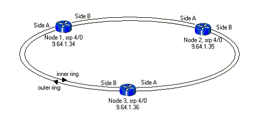
The node where the show srp topology command is issued is the first one listed, and the number of hops associated with this node is 0 (node itself). The next node listed is a node that is one hop away from the first one when you look from the original node B-side. This means that each node listed is connected to the upper node B-side. In the example presented here, Node3 is one hop. This means Node3 is connected to Node2 B-side and Node1 is connected to the Node3 B-side. The last node listed in the show srp topology command output is connected by its B-side to the A-side of the first node listed (the one where you have issued the command).
-
Since B is always connected to A, this is enough data to draw down the topology.
This diagram represents the ring topology:

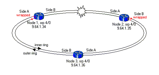
If some nodes in the ring are in wrapped status, the same rule is still present. Draw down the topology and look for the span between neighbors that are wrapped and the SRP interface side that it belongs to. That span has troubles; therefore the other side of the node must be wrapped. Here is an example of the show srp topology command output for such a case:
Node2#show srp topology

 Topology Map for Interface SRP4/0
  Topology pkt. sent every 5 sec. (next pkt. after 0 sec.)
  Last received topology pkt. 00:00:04
  Last topology change was 00:00:09 ago.
  Nodes on the ring: 3
  Hops (outer ring)      MAC       IP Address      Wrapped SRR   Name
      0             0000.4142.8799 9.64.1.35         Yes     -   Node2
      1             0007.0dec.a300 9.64.1.36         No      -   Node3
      2             0010.f60d.7a00 9.64.1.34         Yes     -   Node1
This diagram represents ring topology with two nodes in wrapped status:

Conclusion
You only need the show srp topology command output from one of the nodes that belong to the ring to get a fast drawing of the SRP topology. If you bear in mind the rule that the upper one listed is B-side looking at the lower one, A-side is enough to have a complete drawing of the ring. This is a very useful method for drawing down the SRP topology in small and, especially, in networks with a larger number of nodes.
Note: What is not seen from the show srp topology command output is the slot number for the SRP interface that belongs to the ring. This information is needed only in order to troubleshoot span and can be retrieved in many other ways, such as with the show ip interface brief and show interface commands.
Related Information
Contact Cisco
- Open a Support Case

- (Requires a Cisco Service Contract)
 Feedback