Plugging a SingleMode Fiber Port Into a Multimode Fiber Port
Available Languages
Contents
Introduction
This document answers the question of whether a Synchronous Optical Network (SONET) link can support SingleMode Fiber (SMF) on one end and MultiMode Fiber (MMF) on the other end of an optical link between Cisco routers. This document also explains the difference between SMF and MMF and the current interface modules that support them. At the end of this document, you must be able to identify the interface type and configure the interface.
Prerequisites
Requirements
There are no specific requirements for this document.
Components Used
This document is not restricted to specific software and hardware versions.
The information in this document was created from the devices in a specific lab environment. All of the devices used in this document started with a cleared (default) configuration. If your network is live, make sure that you understand the potential impact of any command.
Conventions
Refer to Cisco Technical Tips Conventions for more information on document conventions.
About Modes
In order to understand how to interconnect modes, you first need to define a mode. There are two typical definitions of a mode, as explained here:
-
Bundles of light rays that enter the fiber at a particular angle.
-
Paths that light rays travel through the fiber. These paths can have different lengths and transmission delays as the light travels through the cable.
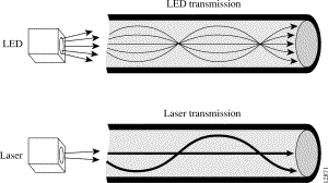
MMF allows multiple modes of light to propagate through the fiber. Multiple modes of light that propagate through the fiber travel different distances, based on the entry angles. The differences in travel speeds cause the modes to arrive at the destination at different times. MMF typically uses Light-Emitting Diodes (LEDs) to launch the optical signal.
SMF allows only one mode of light to propagate through the fiber. SMF uses lasers to launch light in a more concentrated fashion. A laser transmitter couples light into only a fraction of the existing modes or optical pathways present in the fiber-optic cable. Therefore, SMF is capable of higher bandwidth and greater cable run distances than MMF.
Figure 1 illustrates the transmission differences between MMF and SMF.
Figure 1 – Transmission Differences Between MMF and SMF 
Section 4 of the Telecorida GR-253 Specification for SONET Transmission Systems ![]() defines "a small set of application categories and corresponding sets of optical interface specifications."
defines "a small set of application categories and corresponding sets of optical interface specifications."
This table lists these categories, which generally describe the power level and theoretical distance of the transmitted signal:
| Reach | Loss Budget |
|---|---|
| Short | 0 dB and 4 or 7 dB. |
| Intermediate | 0 dB and 11 or 12 dB. |
| Long | 10 dB to 22, 24 or 28 dB, depending on the bit rate. |
| Very-long | Up to 33 dB. (Defined at Optical Carrier-192 (OC-192) bit rates only. ) |
Within the MMF category, only Short Reach (SR) is available. Within the SMF category, two types of transmission are defined:
-
Intermediate Reach (IR)
-
Long Reach (LR)
Typically, POS and Asynchronous Transfer Mode (ATM) over SONET hardware is available in MMF and SMF versions. Here is an example that shows the use of the PA-POS adapter for the 7x00 series.
-
PA-POS-OC3SMI - SMF, IR
-
PA-POS-OC3SML
-
PA-POS-OC3MM - MMF, SR
In most cases, the output of the show diag command indicates the mode type and reach of the optical hardware. The mode type for the PA-POS adapter for the 7x00 Series appears in the show diag command output in a future release of Cisco IOS® Software. As a workaround, look for MM for MultiMode or IR (Intermediate Reach) for SingleMode on the faceplate to determine the model and optics type.
Interconnect the Two Modes
Cisco SONET interfaces support interconnection of SMF and MMF optics. In other words, an MMF receiver at one end, and an SMF receiver at the other end. However, this mismatch of mode types is not officially supported by Cisco Technical Assistance Center (TAC). The reason is that when an unconditioned laser source designed for operation on an SMF cable is directly coupled with an MMF cable, Differential Mode Delay (DMD) can occur. DMD can degrade the modal bandwidth of the fiber-optic cable. This degradation causes a decrease in the link span (the distance between the transmitter and the receiver) that can be reliably supported. In addition, when you interconnect the two modes, take extra care to ensure that the SMF transmitter is attenuated sufficiently to avoid an impact and overdrive of the multimode receiver optics.
Here is a list of third-party vendors who offer devices for converters to interconnect SMF and MMF optics:
Alternatively, you can use an intermediate switch or device with an SMF interface and an MMF interface, which then creates two segments and effectively converts between the nodes.
Related Information
Contact Cisco
- Open a Support Case

- (Requires a Cisco Service Contract)
 Feedback