Understand QoS on Catalyst 6000 Family Switches
Available Languages
Contents
-
Introduction
Defining Layer 2 QoS
The Need for QoS in a Switch
Hardware Support for QoS in the Catalyst 6000 Family
Catalyst 6000 Family Software Support for QoS
Priority Mechanisms in IP and Ethernet
QoS Flow in the Catalyst 6000 Family
Queues, Buffer, Thresholds, and Mappings
WRED or WRR
Configuring Port ASIC Based QoS on the Catalyst 6000 Family
Classification and Policing with the PFC
Common Open Policy Server
Related Information
Introduction
This document explains the Quality of Service (QoS) capabilities available in the Catalyst 6000 family switches. This document covers QoS configuration capabilities and provides some examples of how QoS can be implemented.
This document is not meant to be a configuration guide. Configuration examples are used throughout this paper to assist in the explanation of QoS features of the Catalyst 6000 family hardware and software. For syntax reference for QoS command structures, please refer to the following configuration and command guides for the Catalyst 6000 family:
Defining Layer 2 QoS
While many may think that QoS in Layer 2 (L2) switches is simply about prioritizing Ethernet frames, not many realize that it entails much more. L2 QoS entails the following:
- Input Queue Scheduling: when the frame enters the port, it can be assigned to one of a number of port-based queues prior to being scheduled to being switched to an egress port. Typically, multiple queues are used where different traffic requires different service levels, or where switch latency must be kept to a minimum. For instance, IP based video and voice data requires low latency, so there may be a need to switch this data prior to switching other data such as File Transfer Protocol (FTP), web, email, Telnet, and so on.
- Classification: the process of classification involves inspecting different fields in the Ethernet L2 header, along with fields in the IP header (Layer 3 (L3)) and the Transmission Control Protocol/User Datagram Protocol (TCP/UDP) header (Layer 4 (L4)) to assist in determining the level of service that will be applied to the frame as it transits the switch.
- Policing: policing is the process of inspecting an Ethernet frame to see if it has exceeded a predefined rate of traffic within a certain time frame (typically, this time frame is a fixed number internal to the switch). If that frame be out-of-profile (that is, it is part of a data stream in excess of the predefined rate limit), it can be either dropped or the Class of Service (CoS) value can be marked down.
- Rewriting: the process of rewriting is the ability of the switch to modify the CoS in the Ethernet header or the Type of Service (ToS) bits in the IPV4 header.
- Output Queue Scheduling: after the rewrite processes, the switch will place the Ethernet frame into an appropriate outbound (egress) queue for switching. The switch will perform buffer management on this queue by ensuring that the buffer does not overflow. It will typically do this by utilizing a Random Early Discard (RED) algorithm, whereby random frames are removed (dropped) from the queue. Weighted RED (WRED) is a derivative of RED (used by certain modules in the Catalyst 6000 family), whereby the CoS values are inspected to determine which frames will be dropped. When the buffers reach predefined thresholds, lower priority frames are typically dropped, keeping the higher priority frames in the queue.
This document explains in more detail each of the mechanisms above and how they relate to the Catalyst 6000 family in the following sections.
The Need for QoS in a Switch
Huge backplanes, millions of switched packets per second, and non-blocking switches are all synonymous with many switches today. Why the need for QoS? The answer is because of congestion.
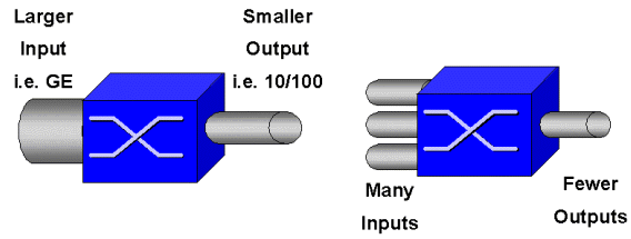
A switch may be the fastest switch in the world, but if you have either of the two scenarios shown in the figure above, that switch will experience congestion. At times of congestion, if the congestion management features are not in place, packets will be dropped. When packets are dropped, retransmissions occur. When retransmissions occur, the network load can increase. In networks that are already congested, this can add to existing performance issues and potentially further degrade performance.
With converging networks, congestion management is even more critical. Latency sensitive traffic such as voice and video can be severely impacted if delays are incurred. Simply adding more buffers to a switch will also not necessarily alleviate congestion problems. Latency sensitive traffic needs to be switched as fast as possible. First, you need to identify this important traffic through classification techniques, and then implement buffer management techniques to avoid the higher priority traffic from being dropped during congestion. Finally, you need to incorporate scheduling techniques to switch important packets from queues as quickly as possible. As you will read in this document, the Catalyst 6000 family implements all of these techniques, making its QoS subsystem one of the most comprehensive in the industry today.
All of the QoS techniques described in the previous section will be explored in more detail throughout this document.
Hardware Support for QoS in the Catalyst 6000 Family
To support QoS in the Catalyst 6000 family, some hardware support is required. The hardware that supports QoS includes the Multilayer Switch Feature Card (MSFC), the Policy Feature Card (PFC), and the Port Application Specific Integrated Circuits (ASICs) on the line cards themselves. This document will not explore the QoS capabilities of the MSFC, rather it will concentrate on the QoS capabilities of the PFC and the ASICs on the line cards.
PFC
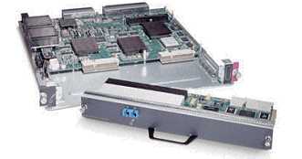
The PFC version 1 is a daughter card that sits on the Supervisor I (SupI) and the Supervisor IA (SupIA) of the Catalyst 6000 family. The PFC2 is a re-spin of the PFC1 and ships with the new Supervisor II (SupII) and some new onboard ASICs. While both the PFC1 and PFC2 are primarily known for their hardware acceleration of L3 switching, QoS is one of their other purposes. The PFCs are shown below.
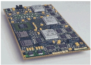
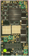
While the PFC 1 and PFC2 are essentially the same, there are some differences in QoS functionality. Namely, the PFC2 adds the following:
- The ability to push down the QoS policy to a Distributed Forwarding Card (DFC).
- Policing decisions are slightly different. Both the PFC1 and PFC2 support normal policing whereby frames are dropped or marked down if an aggregate or microflow policy returns an out-of-profile decision. However, the PFC2 adds support for an excess rate, which indicates a second policing level that policy actions can be taken at.
When an excess rate policer is defined, packets can be dropped or marked down when they exceed the excess rate. If an excess police level is set, the excess DSCP mapping is used to replace the original DSCP value with a marked-down value. If only a normal police level is set, the normal DSCP mapping is used. The excess police level will have precedence for selecting mapping rules when both police levels are set.
It is important to note that the QoS functions described in this document performed by the ASICs mentioned yield high levels of performance. QoS performance in a base Catalyst 6000 family (with no switch fabric module) yields 15 MPPS. Additional performance gains can be achieved for QoS if DFCs are used.
DFC
The DFC can be attached to the WS-X6516-GBIC as an option. However, it is a standard fixture on the WS-X6816-GBIC card. It can also be supported on other future fabric line cards such as the recently introduced fabric 10/100 (WS-X6548-RJ45) line card, fabric RJ21 line card (WS-X6548-RJ21), and the 100FX line card (WS-X6524-MM-FX). The DFC is shown below.
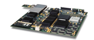
The DFC allows the fabric (crossbar connected) line card to perform local switching. In order to do this, it must also support any QoS policies that have been defined for the switch. The administrator can not directly configure the DFC; rather, it comes under the control of the master MSFC/PFC on the active supervisor. The primary PFC will push down a Forwarding Information Base (FIB) table, which gives the DFC its L2 and L3 forwarding tables. It will also push down a copy of the QoS policies so that they are also local to the line card. Subsequent to this, local switching decisions can reference the local copy of any QoS policies providing hardware QoS processing speeds and yielding higher levels of performance though distributed switching.
Port Based ASICs
To complete the hardware picture, each of the line cards implements a number of ASICs. Those ASICs implement the queues, buffering, and thresholds used for the temporary storage of frames as they transit the switch. On the 10/100 cards, a combination of ASICs is used to provision the 48 10/100 ports.
Original 10/100 Line Cards (WS-X6348-RJ45)
The 10/100 ASICs provide a series of Receive (Rx) and Transmit (TX) queues for each 10/100 port. The ASICs provides 128 K buffering per 10/100 port. Refer to the release notes for details on what per port buffering is available on each line card. Each port on this line card supports one Rx queue and two TX queues denoted high and low. This is shown in the diagram below.
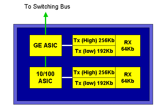
In the diagram above, each 10/100 ASIC provides a breakout for 12 10/100 ports. For each 10/100 port, 128 K buffers are provided. The 128 K of buffers are split between each of the three queues. The figures shown in the above queue are not the defaults, however, they are rather a representation of what could be configured. The single Rx queue gets 16 K, and the remaining memory (112 K) is split between the two Tx queues. By default (in CatOS), the high queue gets 20 percent of this space and the low queue gets 80 percent. In Catalyst IOS, the default is to give the high queue 10 percent and the low queue 90 percent.
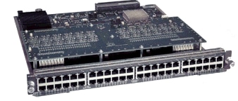
While the card provides dual stage buffering, only 10/100 ASIC based buffering is available to be manipulated during QoS configuration.
Fabric 10/100 Line Cards (WS-X6548-RJ45)
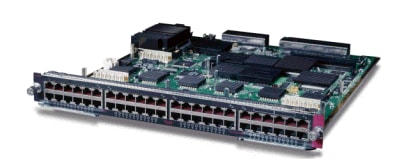
The new 10/100 ASICs provide a series of Rx and TX queues for each 10/100 port. The ASICs provide a shared pool of memory available across the 10/100 ports. Refer to the release notes for details on what per port buffering is available on each line card. Each port on this line card supports two Rx queues and three TX queues. One Rx queue and one TX queue are each denoted as an absolute priority queue. This acts as a low latency queue, which is ideal for latency sensitive traffic such as Voice over IP (VoIP) traffic.
GE Line Cards (WS-X6408A, WS-X6516, WS-X6816)
For GE line cards, the ASIC provides 512 K of per port buffering. A representation of the eight-port GE line card is shown in the diagram below.
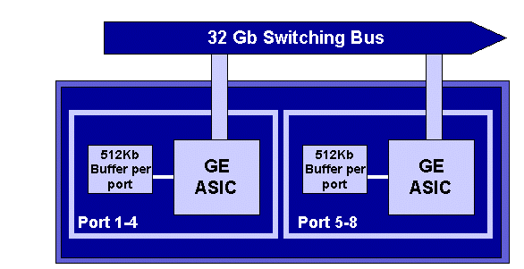
As with the 10/100 ports, each GE port has three queues, one Rx and two TX queues. This is the default on the WS-X6408-GBIC line card, and is shown in the diagram below.
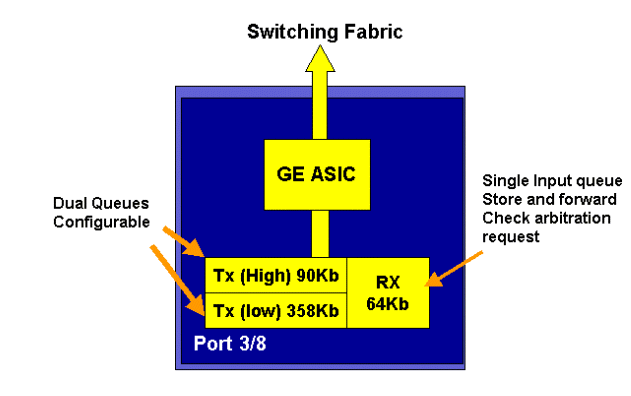
On the newer line 16-port GE cards, the GBIC ports on the SupIA and SupII, and the WS-X6408A-GBIC 8 port GE card, two extra Strict Priority (SP) queues are provided. One SP queue is assigned as a Rx queue and the other is assigned as a TX queue. This SP queue is used primarily for queuing latency sensitive traffic such as voice. With the SP queue, any data placed in this queue will be processed before data in the high and low queues. Only when the SP queue is empty will the high and low queues be serviced.
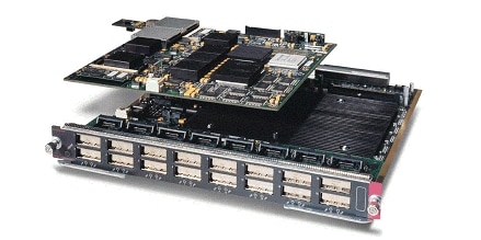
10 GE Line Cards (WS-X6502-10GE)
In the latter half of 2001, Cisco introduced a set of 10 GE line cards providing one port of 10 GE per line card. This module takes one slot from the 6000 chassis. The 10 GE line card supports QoS. For the 10 GE port, it provides two Rx queues and three TX queues. One Rx queue and one TX queue are each designated as a SP queue. Buffering is also provided for the port, providing a total of 256 K of Rx buffering and 64 MB of TX buffering. This port implements a 1p1q8t queue structure for the Rx side and a 1p2q1t queue structure for the TX side. Queue structures are detailed later in this document.
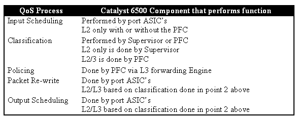
Catalyst 6000 Family QoS Hardware Summary
The hardware components that perform the above QoS functions in the Catalyst 6000 family are detailed in the table below.
Catalyst 6000 Family Software Support for QoS
The Catalyst 6000 family supports two operating systems. The original software platform, CatOS was derived from the code base used on the Catalyst 5000 platform. More recently, Cisco introduced Integrated Cisco IOS ® (Native Mode) (previously known as Native IOS), which uses a code base derived from the Cisco Router IOS. Both OS platforms (CatOS and Integrated Cisco IOS (Native Mode)) implement software support to enable QoS on the Catalyst 6000 switch family platform using the hardware described in the previous sections.
Note: This document uses configuration examples from both OS platforms.
Priority Mechanisms in IP and Ethernet
For any QoS services to be applied to data, there must be a way to tag or prioritize an IP packet or an Ethernet frame. The ToS and the CoS fields are used to achieve this.
ToS
ToS is a one-byte field that exists in an IPV4 header. The ToS field consists of eight bits, of which the first three bits are used to indicate the priority of the IP packet. These first three bits are referred to as the IP precedence bits. These bits can be set from zero to seven, with zero being the lowest priority and seven being the highest priority. Support has been available for setting IP precedence in IOS for many years. Support for resetting IP precedence can be done by the MSFC or by the PFC (independent of the MSFC). A trust setting of untrusted can also wipe out any IP precedence settings on an incoming frame.
The values that can be set for IP precedence are as follows:
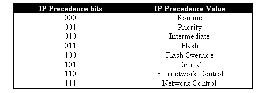
The diagram below is a representation of the IP precedence bits in the ToS header. The three Most Significant Bits (MSB) are interpreted as the IP precedence bits.
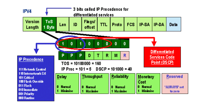
More recently, the use of the ToS field has been expanded to encompass the six MSBs, referred to as DSCP. DSCP results in 64 priority values (two to the power of six) that can be assigned to the IP packet.
The Catalyst 6000 family can manipulate the ToS. This can be achieved using both the PFC and/or the MSFC. When a frame comes into the switch, it will be assigned a DSCP value. This DSCP value is used internally in the switch to assign levels of service (QoS policies) defined by the administrator. The DSCP can already exist in a frame and be used, or the DSCP can be derived from the existing CoS, IP precedence, or DSCP in the frame (should the port be trusted). A map is used internally in the switch to derive the DSCP. With eight possible CoS/IP precedence values and 64 possible DSCP values, the default map will map CoS/IPPrec 0 to DSCP 0, CoS/IPPrec 1 to DSCP 7, CoS/IPPrec 2 to DSCP 15, and so on. These default mappings can be overridden by the administrator. When the frame is scheduled to an outbound port, the CoS can be re-written and the DSCP value is used to derive the new CoS.
CoS
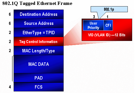
CoS refers to three bits in either an ISL header or an 802.1Q header that are used to indicate the priority of the Ethernet frame as it passes through a switched network. For the purposes of this document, we only refer to the use of the 802.1Q header. The CoS bits in the 802.1Q header are commonly referred to as the 802.1p bits. Not surprisingly, there are three CoS bits, which matches the number of bits used for IP precedence. In many networks, to maintain QoS end to end, a packet may traverse both L2 and L3 domains. To maintain QoS, the ToS can be mapped to CoS, and CoS can be mapped to ToS.
The diagram below is an Ethernet frame tagged with an 802.1Q field, which consists of a two-byte Ethertype and a two-byte tag. Within the two-byte tag are the user priority bits (known as 802.1p).
QoS Flow in the Catalyst 6000 Family
QoS in the Catalyst 6000 family is the most comprehensive implementation of QoS in all of the current Cisco Catalyst switches. The following sections describe how the various QoS processes are applied to a frame as it transits the switch.
Earlier in this document, it was noted that there are a number of QOS elements that many L2 and L3 switches can offer. Those elements are classification, input queue scheduling, policing, rewriting, and output queue scheduling. The difference with the Catalyst 6000 family is that these QoS elements are applied by a L2 engine that has insight into L3 and L4 details as well as just L2 header information. The following diagram summarizes how the Catalyst 6000 family implements these elements.
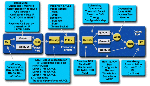
A frame enters the switch and is initially processed by the port ASIC that received the frame. It will place the frame into a Rx queue. Depending on the Catalyst 6000 family line card, there will be one or two Rx queues.
The port ASIC will use the CoS bits as an indicator of which queue to place the frame into (if multiple input queues are present). If the port is classified as untrusted, the port ASIC can overwrite the existing CoS bits based on a predefined value.
The frame is then passed to the L2/L3 forwarding engine (PFC), which will classify and optionally police (rate limit) the frame. Classification is the process of assigning the frame a DSCP value, which is used internally by the switch for processing the frame. The DSCP will be derived from one of the following:
- An existing DSCP value set prior to the frame entering the switch
- The received IP precedence bits already set in the IPV4 header. As there are 64 DSCP values and only eight IP precedence values, the administrator will configure a mapping that is used by the switch to derive the DSCP. Default mappings are in place should the administrator not configure the maps.
- The received CoS bits already set prior to the frame entering the switch. Similar to IP precedence, there are a maximum of eight CoS values, each of which must be mapped to one of 64 DSCP values. This map can be configured or the switch can use the default map in place.
- Set for the frame by using a DSCP default value typically assigned though an Access Control List (ACL) entry.
After a DSCP value is assigned to the frame, the policing (rate limiting) is applied, should a policing configuration exist. Policing will limit the flow of data through the PFC by dropping or marking down traffic that is out-of-profile. Out-of-profile is a term used to indicate that traffic has exceeded a limit defined by the administrator as the amount of bits per second the PFC will send. Out-of-profile traffic can be dropped or the CoS value can be marked down. The PFC1 and PFC2 currently only support input policing (rate limiting). Support for input and output policing will be available with the release of a new PFC.
The PFC will then pass the frame to the egress port for processing. At this point, a rewrite process is invoked to modify the CoS values in the frame and the ToS value in the IPV4 header. This is derived from the internal DSCP. The frame will then be placed into a transmit queue based on its CoS value, ready for transmission. While the frame is in the queue, the port ASIC will monitor the buffers and implement WRED to avoid the buffers from overflowing. A WRR scheduling algorithm is then used to schedule and transmit frames from the egress port
Each of the sections below will explore this flow in more detail giving configuration examples for each of the steps described above.
Queues, Buffers, Thresholds, and Mappings
Before QoS configuration is described in detail, certain terms must be explained further to ensure that you fully understand the QoS configuration capabilities of the switch.
Queues
Each port on the switch has a series of input and output queues that are used as temporary storage areas for data. Catalyst 6000 family line cards implement different numbers of queues for each port. The queues are usually implemented in hardware ASICs for each port. On the first generation Catalyst 6000 family line cards, the typical configuration was one input queue and two output queues. On newer line cards (10/100 and GE), the ASIC implements an extra set of two queues (one input and one output) resulting in two input queues and three output queues. These two extra queues are special SP queues used for latency sensitive traffic such as VoIP. They are serviced in a SP fashion. That is, if a frame arrives in the SP queue, scheduling frames from the lower queues is ceased to process the frame in the SP queue. Only when the SP queue is empty will scheduling of packets from the lower queue(s) recommence.
When a frame arrives at a port (for input or output) at times of congestion, it will be placed into a queue. The decision behind which queue the frame is placed in will typically be done based on the CoS value in the Ethernet header of the incoming frame.
On egress, a scheduling algorithm will be employed to empty the TX (output) queue. WRR is the technique employed to achieve this. For each queue, a weighting is used to dictate how much data will be emptied from the queue before moving onto the next queue. The weighting assigned by the administrator is a number from 1 to 255 and this is assigned to each TX queue.
Buffers
Each queue is assigned a certain amount of buffer space to store transit data. Resident on the port ASIC is memory, which is split up and allocated on a per port basis. For each GE port, the GE ASIC assigns 512 K of buffer space. For 10/100 ports, the port ASIC reserves 64 K or 128 K (depending on the line card) of per port buffering. This buffer space is then divided up between the Rx (ingress) queue and the TX (egress) queues.
Thresholds
One aspect of normal data transmission is that if a packet is dropped, it will result in that packet being retransmitted (TCP flows). At times of congestion, this can add to the load on the network and potentially cause buffers to overload even more. As a means of ensuring that buffers do not overflow, the Catalyst 6000 family switch employs a number of techniques to avoid this from happening.
Thresholds are imaginary levels assigned by the switch (or the administrator) that define utilization points at which the congestion management algorithm can start dropping data from the queue. On the Catalyst 6000 family ports, there are typically four thresholds that are associated with input queues. There are usually two thresholds associated with output queues.
These thresholds are also deployed, in the context of QoS, as a way to assign frames with different priorities to these thresholds. As the buffer begins to fill and thresholds are breached, the administrator can map different priorities to different thresholds indicating to the switch which frames should be dropped when a threshold is exceeded.
Mappings
In the queues and threshold sections above, it was mentioned that the CoS value in the Ethernet frame is used to determine which queue to place the frame into and at what point of the buffer filling up is a frame eligible to be dropped. This is the purpose of mappings.
When QoS is configured on the Catalyst 6000 family, default mappings are enabled that define the following:
- at what thresholds frames with specific CoS values are eligible to be dropped
- which queue a frame is placed into (based on its CoS value)
While the default mappings exist, these default mappings can be overridden by the administrator. Mapping exists for the following:
- CoS values on an incoming frame to a DSCP value
- IP precedence values on an incoming frame to a DSCP value
- DSCP values to a CoS value for an outgoing frame
- CoS values to drop thresholds on receive queues
- CoS values to drop thresholds on transmit queues
- DSCP markdown values for frames that exceed policing statements
- CoS values to a frame with a specific destination MAC address
WRED and WRR
WRED and WRR are two extremely powerful algorithms resident on the Catalyst 6000 family. Both WRED and WRR use the priority tag (CoS) inside an Ethernet frame to provide enhanced buffer management and outbound scheduling. B
WRED
WRED is a buffer management algorithm employed by the Catalyst 6000 family to minimize the impact of dropping high priority traffic at times of congestion. WRED is based on the RED algorithm.
In order to understand RED and WRED, revisit the concept of TCP flow management. Flow management ensures that the TCP sender does not overwhelm the network. The TCP slowstart algorithm is part of the solution to address this. It dictates that when a flow starts, a single packet is sent before it waits for an acknowledgment. Two packets are then sent before an ACK is received, gradually increasing the number of packets sent before each ACK is received. This will continue until the flow reaches a transmission level (that is, sends x number of packets) that the network can handle without the load incurring congestion. If congestion occurs, the slowstart algorithm will throttle back the window size (that is, the number of packets sent before waiting for an acknowledgment), thus reducing overall performance for that TCP session (flow).
RED will monitor a queue as it starts to fill up. Once a certain threshold has been exceeded, packets will start to be dropped randomly. No regard is given to specific flows; rather, random packets will be dropped. These packets could be from high or low priority flows. Dropped packets can be part of a single flow or multiple TCP flows. If multiple flows are impacted, as described above, this can have a considerable impact on each flows window size.
Unlike RED, WRED is not as random when dropping frames. WRED takes into consideration the priority of the frames (in the Catalyst 6000 family case it uses the CoS value). With WRED, the administrator assigns frames with certain CoS values to specific thresholds. Once these thresholds are exceeded, frames with CoS values that are mapped to these thresholds are eligible to be dropped. Other frames with CoS values assigned to the higher thresholds are kept in the queue. This process allows for higher priority flows to be kept intact keeping their larger window sizes intact and minimizing the latency involved in getting the packets from the sender to the receiver.
How do you know if your line card supports WRED? Issue the following command. In the output, check for the section that indicates support for WRED on that port.
Console> show qos info config 2/1
QoS setting in NVRAM:
QoS is enabled
Port 2/1 has 2 transmit queue with 2 drop thresholds (2q2t).
Port 2/1 has 1 receive queue with 4 drop thresholds (1q4t).
Interface type:vlan-based
ACL attached:
The qos trust type is set to untrusted.
Default CoS = 0
Queue and Threshold Mapping:
Queue Threshold CoS
----- --------- ---------------
1     1         0 1
1     2         2 3
2     1         4 5
2     2         6 7
Rx drop thresholds:
Rx drop thresholds are disabled for untrusted ports.
Queue #  Thresholds - percentage (abs values)
-------  -------------------------------------
1        50% 60% 80% 100%
TX drop thresholds:
Queue #  Thresholds - percentage (abs values)
-------  -------------------------------------
1        40% 100%
2        40% 100%
TX WRED thresholds:
WRED feature is not supported for this port_type.
!-- Look for this.
Queue Sizes:
Queue #  Sizes - percentage (abs values)
-------  -------------------------------------
1        80%
2        20%
WRR Configuration of ports with speed 1000MBPS:
Queue #  Ratios (abs values)
-------  -------------------------------------
1        100
2        255
Console> (enable)
In the event that WRED is not available on a port, the port will use a tail drop method of buffer management. Tail drop, as its name implies, simply drops incoming frames once the buffers have been fully utilized.
WRR
WRR is used to schedule egress traffic from TX queues. A normal round robin algorithm will alternate between TX queues sending an equal number of packets from each queue before moving to the next queue. The weighted aspect of WRR allows the scheduling algorithm to inspect a weighting that has been assigned to the queue. This allows defined queues access to more of the bandwidth. The WRR scheduling algorithm will empty out more data from identified queues than other queues, thus providing a bias for designated queues.
Configuration for WRR and the other aspects of what have been described above are explained in the following sections.
Configuring Port ASIC Based QoS on the Catalyst 6000 Family
QoS configuration instructs either the port ASIC or the PFC to perform a QoS action. The following sections will look at QoS configuration for both these processes. On the port ASIC, QoS configuration affects both inbound and outbound traffic flows.
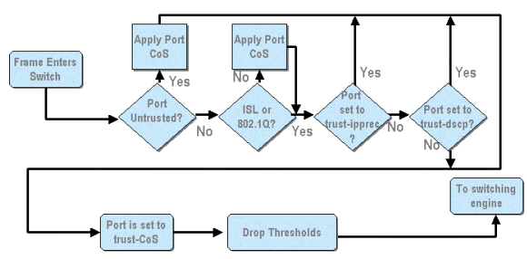
From the above diagram, it can be seen that the following QoS configuration processes apply:
- trust states of ports
- applying port based CoS
- Rx drop threshold assignment
- CoS to Rx drop threshold maps
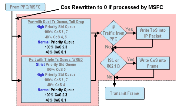
When a frame is processed by either the MSFC or the PFC, it is passed to the outbound port ASIC for further processing. Any frames processed by the MSFC will have their CoS values reset to zero. This needs to be taken into consideration for QoS processing on outbound ports.
The above diagram shows QoS processing performed by the port ASIC for outbound traffic. Some of the processes invoked on outbound QoS processing include the following:
- TX tail drop and WRED threshold assignments
- CoS to TX tail drop and WRED maps
Also, not shown on the diagram above, is the process of reassigning the CoS to the outbound frame using a DSCP to CoS map.
The following sections examine the QoS configuration capabilities of the port based ASICs in more detail.
Note: An important point to make is that when QoS commands are invoked using CatOS, they typically apply to all ports with the specified queue type. For example, if a WRED drop threshold is applied to ports with queue type 1p2q2t, this WRED drop threshold is applied to all ports on all line cards supporting this queue type. With Cat IOS, QoS commands are typically applied at the interface level.
Enabling QoS
Before any QOS configuration can take place on the Catalyst 6000 family, QoS must first be enabled on the switch. This is achieved by issuing the following command:
CatOS
Console> (enable) set qos enable
!-- QoS is enabled.
Console> (enable)
Integrated Cisco IOS (Native Mode)
Cat6500(config)# mls qos
When QoS is enabled in the Catalyst 6000 family, the switch will set a series of QoS defaults for the switch. These defaults include the following settings:
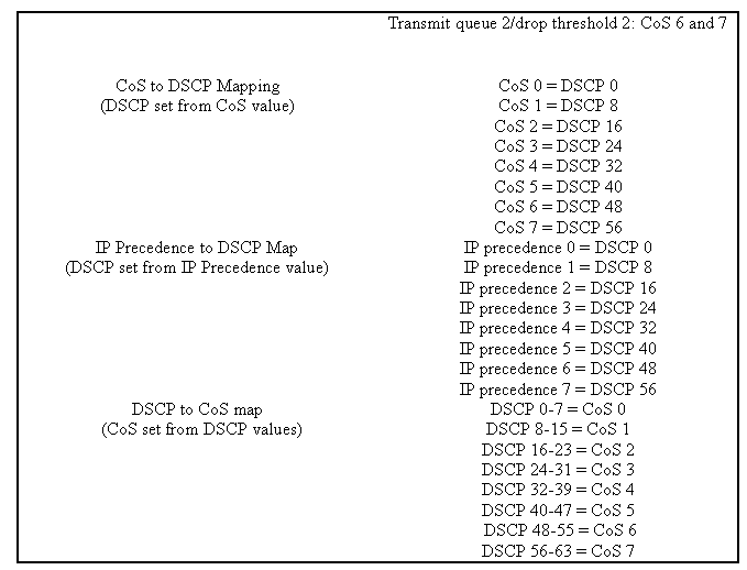
Trusted and Untrusted Ports
Any given port on the Catalyst 6000 family can be configured as trusted or UN-trusted The trust state of the port dictates how it marks, classifies, and schedules the frame as it transits the switch. By default, all ports are in the untrusted state.
Untrusted Ports (Default Setting for Ports)
Should the port be configured as an untrusted port, a frame upon initially entering the port will have its CoS and ToS value reset by the port ASIC to zero. This means the frame will be given the lowest priority service on its path through the switch.
Alternatively, the administrator can reset the CoS value of any Ethernet frame that enters an untrusted port to a pre-determined value. Configuring this will be discussed in a later section.
Setting the port as untrusted will instruct the switch to not perform any congestion avoidance. Congestion avoidance is the method used to drop frames based on their CoS values once they exceed thresholds defined for that queue. All frames entering this port will equally be eligible to be dropped once the buffers reach 100 percent.
In CatOS, a 10/100 or GE port can be configured as untrusted by issuing the following command:
CatOS
Console> (enable) set port qos 3/16 trust untrusted
!-- Port 3/16 qos set to untrusted.
Console> (enable)
This command sets port 16 on module 3 to a state of untrusted.
Note: For Integrated Cisco IOS (Native Mode), the software currently only supports setting trust for GE ports.
Integrated Cisco IOS (Native Mode)
Cat6500(config)# interface gigabitethernet 1/1
Cat6500(config-if)# no mls qos trust
In the example above, we enter the interface configuration and apply the no form of the command to set the port as untrusted since it is IOS.
Trusted Ports
At times, Ethernet frames entering a switch will have either a CoS or ToS setting that the administrator wants the switch to maintain as the frame transits the switch. For this traffic, the administrator can set the trust state of a port where that traffic comes into the switch as trusted.
As mentioned earlier, the switch uses a DSCP value internally to assign a predetermined level of service to that frame. As a frame enters a trusted port, the administrator can configure the port to look at either the existing CoS, IP precedence, or DSCP value to set the internal DSCP value. Alternatively, the administrator can set a predefined DSCP to every packet that enters the port.
Setting the trust state of a port to trusted can be achieved by issuing the following command:
CatOS
Console> (enable) set port qos 3/16 trust trust-cos
!-- Port 3/16 qos set to trust-COs
Console> (enable)
This command is applicable on the WS-X6548-RJ45 line card and sets the trust state of port 3/16 to trusted. The switch will use the CoS value set in the incoming frame to set the internal DSCP. The DSCP is derived from either a default map that was created when QoS was enabled on the switch, or alternatively from a map defined by the administrator. In place of the trust-COs keyword, the administrator can also use the trust-dscp or trust-ipprec keywords.
On previous 10/100-line cards (WS-X6348-RJ45 and WS-X6248-RJ45), port trust needs to be set by issuing the set qos acl command. In this command, a trust state can be assigned by a sub parameter of the set qos acl command. Setting trust CoS on ports on these line cards is not supported, as shown below.
Console> (enable) set port qos 4/1 trust trust-COs
Trust type trust-COs not supported on this port.
!-- Trust-COs not supported, use acl instead.
Rx thresholds are enabled on port 4/1.
!-- Need to turn on input queue scheduling.
Port  4/1 qos set to untrusted.
!-- Trust-COs not supported, so port is set to untrusted.
The command above does indicate that it is required to enable input queue scheduling. Thus, for 10/100 ports on WS-X6248-RJ45 and WS-X6348-RJ45 line cards, the set port qos x/y trust trust-COs command must still be configured, although to set trust states, the ACL must be used.
With Integrated Cisco IOS (Native Mode), the setting of trust can be performed on a GE interface and 10/100 ports on the new WS-X6548-RJ45 line card.
Integrated Cisco IOS (Native Mode)
Cat6500(config)# interface gigabitethernet 5/4
Cat6500(config-if)# mls qos trust ip-precedence
Cat6500(config-if)#
This example sets the trust state of GE port 5/4 to trusted. The frame's IP precedence value will be used to derive the DSCP value.
Input Classification and Setting Port Based CoS
On ingress to a switch port, an Ethernet frame can have its CoS changed if it meets one of the following two criteria:
- port is configured as untrusted, or
- the Ethernet frame does not have an existing CoS value already set
If you wish to re-configure the CoS of an incoming Ethernet frame, you should issue the following command:
CatOS
Console> (enable) set port qos 3/16 cos 3
!-- Port 3/16 qos set to 3.
Console> (enable)
This command sets the COs of incoming Ethernet frames on port 16 on module 3 to a value of 3 when an unmarked frame arrives or if the port is set to untrusted.
Integrated Cisco IOS (Native Mode)
Cat6500(config)# interface fastethernet 5/13
Cat6500(config-if)# mls qos COs 4
Cat6500(config-if)#
This command sets the COs of incoming Ethernet frames on port 13 on module 5 to a value of 4 when an unmarked frame arrives or if the port is set to untrusted.
Configure Rx Drop Thresholds
On ingress to the switch port, the frame will be placed into a Rx queue. To avoid buffer overflows, the port ASIC implements four thresholds on each Rx queue and uses these thresholds to identify frames that can be dropped once those thresholds have been exceeded. The port ASIC will use the frames set COs value to identify which frames can be dropped when a threshold is exceeded. This capability allows higher priority frames to remain in the buffer for longer when congestion occurs.
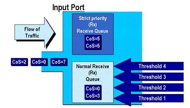
As shown in the above diagram, frames arrive and are placed in the queue. As the queue starts to fill, the thresholds are monitored by the port ASIC. When a threshold is breached, frames with COs values identified by the administrator are dropped randomly from the queue. The default threshold mappings for a 1q4t queue (found on WS-X6248-RJ45 and WS-X6348-RJ45 line cards) are as follows:
- threshold 1 is set to 50% and COs values 0 and 1 are mapped to this threshold
- threshold 2 is set to 60% and COs values 2 and 3 are mapped to this threshold
- threshold 3 is set to 80% and COs values 4 and 5 are mapped to this threshold
- threshold 4 is set to 100% and COs values 6 and 7 are mapped to this threshold
For a 1P1q4t (found on GE ports) queue, the default mappings are as follows:
- threshold 1 is set to 50% and COs values 0 and 1 are mapped to this threshold
- threshold 2 is set to 60% and COs values 2 and 3 are mapped to this threshold
- threshold 3 is set to 80% and COs values 4 are mapped to this threshold
- threshold 4 is set to 100% and COs values 6 and 7 are mapped to this threshold
- COs Value of 5 is mapped to the strict priority queue
For a 1p1q0t (found on 10/100 ports on the WS-X6548-RJ45 line card), the default mappings are as follows:
- Frames with COs 5 go to the SP Rx queue (queue 2), where the switch drops incoming frames only when the SP receive-queue buffer is 100 percent full.
- Frames with COs 0, 1, 2, 3, 4, 6, or 7 go to the standard Rx queue. The switch drops incoming frames when the Rx-queue buffer is 100 percent full.
These drop thresholds can be changed by the administrator. Also, the default COs values that are mapped to each threshold can also be changed. Different line cards implement different Rx queue implementations. A summary of the queue types is shown below.
CatOS
Console> (enable) set qos drop-threshold 1q4t rx queue 1 20 40 75 100
!-- Rx drop thresholds for queue 1 set at 20%, 40%, 75%, and 100%.
Console> (enable)
This command sets the receive drop thresholds for all input ports with one queue and four thresholds (denotes 1q4t) to 20%, 40%, 75%, and 100%.
The command issued in Integrated Cisco IOS (Native Mode) is shown below.
Integrated Cisco IOS (Native Mode)
Cat6500(config-if)# wrr-queue threshold 1 40 50
Cat6500(config-if)# wrr-queue threshold 2 60 100

!-- Configures the 4 thresholds for a 1q4t rx queue and.

Cat6500(config-if)# rcv-queue threshold 1 60 75 85 100

!-- Configures for a 1p1q4t rx queue, which applies to
!-- the new WS-X6548-RJ45 10/100 line card.
Rx drop thresholds must be enabled by the administrator. Currently, the set port qos x/y trust trust-COs command should be used to activate the Rx drop thresholds (where x is the module number and y is the port on that module).
Configuring TX Drop Thresholds
On an egress port, the port will have two TX thresholds that are used as part of the congestion avoidance mechanism, queue 1 and queue 2. Queue 1 is denoted as the standard low priority queue, and queue 2 is denoted as the standard high priority queue. Depending on the line cards used, they will employ either a tail drop or a WRED threshold management algorithm. Both algorithms employ two thresholds for each TX queue.
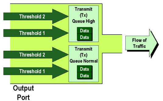
The administrator can manually set these thresholds as follows:
CatOS
Console> (enable) set qos drop-threshold 2q2t TX queue 1 40 100
!-- TX drop thresholds for queue 1 set at 40% and 100%.
Console> (enable)
This command sets the TX drop thresholds for queue 1 for all output ports with two queues and two thresholds (denotes 2q2t) to 40% and 100%.
Console> (enable) set qos wred 1p2q2t TX queue 1  60 100
!-- WRED thresholds for queue 1 set at 60% 100% on all WRED-capable 1p2q2t ports.
Console> (enable)
This command sets the WRED drop thresholds for queue 1 for all output ports with one SP queue, two normal queues, and two thresholds (denotes 1p2q2t) to 60% and 100%. Queue 1 is defined as the normal low priority queue and has the lowest priority. Queue 2 is the high priority normal queue and has a higher priority than queue 1. Queue 3 is the SP queue and is serviced ahead of all other queues on that port.
The equivalent command issued in Integrated Cisco IOS (Native Mode) is shown below.
Integrated Cisco IOS (Native Mode)
Cat6500(config-if)# wrr-queue random-detect max-threshold  1 40 100
Cat6500(config-if)#
This sets the WRED drop thresholds for a 1p2q2t port to queue 1 to 40% for threshold 1 (TX) and 100% for threshold 2 (TX).
WRED can also be disabled if required in Integrated Cisco IOS (Native Mode). The method used to do this is to use the n" form of the command. An example of disabling WRED is shown as follows:
Integrated Cisco IOS (Native Mode)
Cat6500(config-if)# no wrr-queue random-detect queue_id
Mapping MAC Address to COs Values
In addition to setting COs based on a global port definition, the switch allows the administrator to set COs values based on the destination MAC address and VLAN ID. This allows for frames destined for specific targets to be tagged with a predetermined COs value. This configuration can be achieved by issuing the following command:
CatOS
Console> (enable) set qos Mac-COs 00-00-0c-33-2a-4e 200 5
!-- COs 5 is assigned to 00-00-0c-33-2a-4e VLAN 200.
Console> (enable)
This command sets a COs of 5 for any frame whose destination MAC address is 00-00-0c-33-2a-4e that was from VLAN 200.
There is no equivalent command in Integrated Cisco IOS (Native Mode). This is because this command is only supported when no PFC is present and Integrated Cisco IOS (Native Mode) requires a PFC to function.
Mapping COs to Thresholds
After thresholds have been configured, the administrator can then assign COs values to these thresholds, so that when the threshold has been exceeded, frames with specific COs values can be dropped. Usually, the administrator will assign lower priority frames to the lower thresholds, thus maintaining higher priority traffic in the queue should congestion occur.
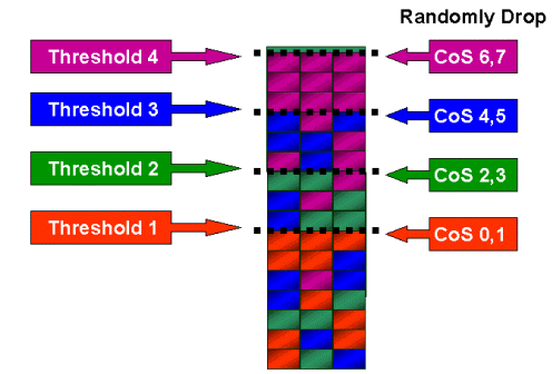
The above figure shows an input queue with four thresholds, and how COs values have been assigned to each threshold.
The following output shows how COs values can be mapped to thresholds:
CatOS
Console> (enable) set qos map 2q2t 1 1 COs 0 1
!-- QoS TX priority queue and threshold mapped to COs successfully.
Console> (enable)
This command assigns COs values of 0 and 1 to queue 1, threshold 1. The equivalent command in Integrated Cisco IOS (Native Mode) is shown below.
Integrated Cisco IOS (Native Mode)
Cat6500(config-if)# wrr-queue COs-map  1  1  0  1
Cat6500(config-if)#
Configure Bandwidth on TX Queues
When a frame is placed in an output queue, it will be transmitted using an output-scheduling algorithm. The output scheduler process uses WRR to transmit frames from the output queues. Depending on the line card hardware being used, there are either two, three, or four transmit queues per port.
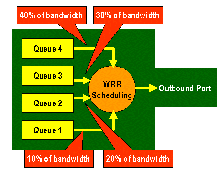
On the WS-X6248 and WS-X6348 line cards (with 2q2t queue structures), two TX queues are used by the WRR mechanism for scheduling. On the WS-X6548 line cards (with a 1p3q1t queue structure) there are four TX queues. Of these four TX queues, three TX queues are serviced by the WRR algorithm (the last TX queue is a SP queue). On GE line cards, there are three TX queues (using a 1p2q2t queue structure); one of these queues is a SP queue so the WRR algorithm only services two TX queues.
Typically, the administrator will assign a weight to the TX queue. WRR works by looking at the weighting assigned to the port queue, which is used internally by the switch to determine how much traffic will be transmitted before moving onto the next queue. A weighting value of between 1 and 255 can be assigned to each of the port queue.
CatOS
Console> (enable) set qos wrr 2q2t 40 80
!-- QoS wrr ratio set successfully.
Console> (enable)
This command assigns a weighting of 40 to queue 1 and 80 to queue 2. This effectively means a two to one ratio (80 to 40 = 2 to 1) of bandwidth assigned between the two queues. This command takes effect on all ports with two queues and two thresholds on ports.
The equivalent command issued in Integrated Cisco IOS (Native Mode) is shown below.
Integrated Cisco IOS (Native Mode)
Cat6500(config-if)# wrr-queue bandwidth 1 3
Cat6500(config-if)#
The above represents a three to one ratio between the two queues. You will notice that the Cat IOS version of this command applies to a specific interface only.
DSCP to COs Mapping
When the frame has been placed into the egress port, the port ASIC will use the assigned COs to perform congestion avoidance (that is, WRED) and also use the COs to determine the scheduling of the frame (that is, transmitting the frame). At this point, the switch will use a default map to take the assigned DSCP and map that back to a COs value. This default map is displayed in this table.
Alternatively, the administrator can create a map that will be used by the switch to take the assigned internal DSCP value and create a new COs value for the frame. Examples of how you would use CatOS and Integrated Cisco IOS (Native Mode) to achieve this are shown below.
CatOS
Console> (enable) set qos dscp-cos--map 20-30:5 10-15:3 45-52:7
!-- QoS dscp-cos-map set successfully.
Console> (enable)
The above command maps DSCP values 20 through to 30 to a COs value of 5, DSCP values 10 through 15 to a COs of 3, and DSCP values 45 though to 52 to a COs value of 7. All other DSCP values use the default map created when QoS was enabled on the switch.
The equivalent command issued in Integrated Cisco IOS (Native Mode) is shown below.
Integrated Cisco IOS (Native Mode)
Cat6500(config)# mls qos map dscp-cos 20 30 40 50 52 10 1 to 3
Cat6500(config)#
This sets DSCP values of 20, 30, 40, 50, 52, 10, and 1 to a COs value of 3.
Classification and Policing with the PFC
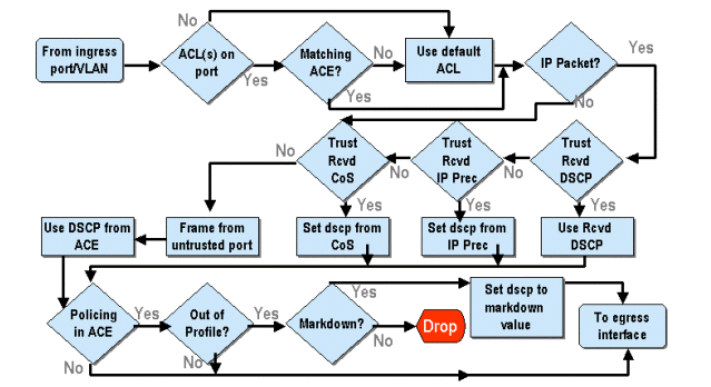
The PFC supports the classification and the policing of frames. Classification can use an ACL to assign (mark) an incoming frame with a priority (DSCP). Policing allows a stream of traffic to be limited to a certain amount of bandwidth.
The following sections will describe these capabilities on the PFC from the perspective of both the CatOS and the Integrated Cisco IOS (Native Mode) OS platforms. The processes applied by the PFC are shown in the following diagram:
Configure Policing on the Catalyst 6000 Family with CatOS
The function of policing is broken up into two sections, one for CatOS and one for Integrated Cisco IOS (Native Mode). Both achieve the same end result, but are configured and implemented in different ways.
Policing
The PFC supports the ability to rate limit (or police) incoming traffic to the switch and can reduce the flow of traffic to a predefined limit. Traffic in excess of that limit can be dropped or have the DSCP value in the frame marked down to a lower value.
Output (egress) rate limiting is currently not supported in either the PFC1 or the PFC2. This will be added in a new revision of the PFC planned for the second half of 2002 that will support output (or egress) policing.
Policing is supported in both the CatOS and the new Integrated Cisco IOS (Native Mode), although the configuration of these features is very different. The following sections will describe the configuration of policing in both OS platforms.
Aggregates and Microflows (CatOS)
Aggregates and Microflows are terms used to define the scope of policing that the PFC performs.
A microflow defines the policing of a single flow. A flow is defined by a session with a unique SA/DA MAC address, SA/DA IP address, and TCP/UDP port numbers. For each new flow that is initiated through a port of a VLAN, the microflow can be used to limit the amount of data received for that flow by the switch. In the microflow definition, packets that exceed the prescribed rate limit can be either dropped or have their DSCP value marked down.
Similar to a microflow, an aggregate can be used to rate limit traffic. However, the aggregate rate applies to all traffic inbound on a port or VLAN that matches a specified QoS ACL. You can view the aggregate as the policing of cumulative traffic that matches the profile in the Access Control Entry (ACE).
Both the aggregate and the microflow define the amount of traffic that can be accepted into the switch. Both an aggregate and a microflow can be assigned at the same time to a port or a VLAN.
When defining microflows, up to 63 of them can be defined and up to 1023 aggregates can be defined.
Access Control Entries and QoS ACLs (CatOS)
A QoS ACL consists of a list of ACEs defining a set of QoS rules that the PFC uses to process incoming frames. Aces are similar to a Router Access Control List (RACL). The ACE defines classification, marking, and policing criteria for an incoming frame. If an incoming frame matches the criteria set in the ACE, the QoS engine will process the frame (as deemed by the ACE).
All QoS processing is done in hardware, so enabling QoS policing does not impact the performance of the switch.
The PFC2 currently supports up to 500 ACLs and those ACLs can consist of up to 32000 Aces (in total). Actual ACE numbers will depend on other services defined and available memory in the PFC.
There are three types of Aces that can be defined. They are IP, IPX, and MAC. Both IP and IPX Aces inspect L3 header information, whereas MAC based Aces only inspect L2 header information. It should also be noted that MAC Aces can only be applied to non-IP and non-IPX traffic.
Creating Policing Rules
The process of creating a policing rule entails creating an aggregate (or microflow), then mapping that aggregate (or microflow) to an ACE.
If, for example, the requirement was to limit all incoming IP traffic on port 5/3 to a maximum of 20 MB, the two steps mentioned above must be configured.
First, the example requests all incoming IP traffic to be limited. This implies that an aggregate policer must be defined. An example of this might be as follows:
Console> (enable) set qos policer aggregate test-flow rate 20000 burst 13 policed-dscp !-- Hardware programming in progress !-- QoS policer for aggregate test-flow created successfully. Console> (enable)
We have created aggregate called test-flow. It defines a rate of 20000 KBPS (20MBPS) and a burst of 13. The policed-dscp keyword indicates that any data exceeding this policy will have its DSCP value marked down as specified in a DSCP markdown map (a default one exists or this can be modified by the administrator). An alternate to using the policed-dscp keyword is to use the drop keyword. The drop keyword will simply drop all out-of-profile traffic (traffic that falls outside the allotted burst value).
The policing facility works on a leaky token bucket scheme, in that you define a burst (which is the amount of data in bits per second that you will accept in a given (fixed) time interval), and then the rate (which is defined as the amount of data that you will empty out that bucket in a single second). Any data that overflows this bucket is either dropped or has its DSCP marked down. The given time period (or interval) mentioned above is 0.00025 seconds (or 1/4000th of a second) and is fixed (that is, you cannot use any configuration commands to change this number).
The number 13 from the example above represents a bucket that will accept up to 13,000 bits of data every 1/4000th of a second. This relates to 52 MB a second (13K * (1 / 0.00025) or 13K * 4000). You must always ensure that your burst is configured to be equal to or higher than the rate at which you want to send data out. In other words, the burst should be greater than or equal to the minimum amount of data you wish to transmit for a given period. If the burst results in a lower figure to what you have specified as your rate, the rate limit will equal the burst. In other words, if you define a rate of 20 MBPS and a burst that calculates to 15MBPS, your rate will only ever get to 15MBPS. The next question you might ask is why 13? Remember the burst defines the depth of the token bucket, or in other words, the depth of the bucket used to receive incoming data every 1/4000th of a second. So, the burst could be any number supported on an arrival data rate greater than or equal to 20 MB a second. The minimum burst that one could use for a rate limit of 20MB is 20000/4000 = 5.
When processing the policer, the policing algorithm starts off by filling the token bucket with a full complement of tokens. The number of tokens equals the burst value. So, if the burst value is 13, the number of tokens in the bucket equals 13,000. For every 1/4000th of a second, the policing algorithm will send out an amount of data equal to the defined rate divided by 4000. For every bit (binary digit) of data sent, it consumes one token from the bucket. At the end of the interval, it will replenish the bucket with a new set of tokens. The number of tokens it replaces is defined by the rate / 4000. Consider the example above to understand this:
Console> (enable) set qos policer aggregate test-flow rate 20000 burst 13
Assume this is a 100 MBPS port and we are sending in a constant stream of 100 MBPS into the port. We know that this will equate to an incoming rate of 100,000,000 bits per second. The parameters here are a rate of 20000 and burst of 13. At time interval t0, there is a full complement of tokens in the bucket (which is 13,000). At time interval t0, we will have the first set of data arrive into the port. For this time interval, the arrival rate will be 100,000,000 / 4000 = 25,000 bits per second. As our token bucket only has a depth of 13,000 tokens, only 13,000 bits of the 25,000 bits arriving into the port in this interval are eligible for being sent and 12,000 bits are dropped.
The specified rate defines a forwarding rate of 20,000,000 bits per second, which equals 5,000 bits sent per 1/4000th interval. For every 5,000 bits sent, there are 5,000 tokens consumed. At time interval T1, another 25,000 bits of data arrives, but the bucket drops 12,000 bits. The bucket is replenished with tokens defined as the rate / 4000 (which equals 5,000 new tokens). The algorithm then sends out the next complement of data, which equals another 5,000 bits of data (this consumes another 5,000 tokens) and so on for each interval.
Essentially, any data coming in excess of the bucket depth (defined burst) is dropped. Data left over after data has been sent (matching the stated the rate) is also dropped, making way for the next set of arriving data. An incomplete packet is one that has not fully been received within the time interval is not dropped but kept until it has been fully received into the port.
This burst number assumes a constant flow of traffic. However, in real world networks, data is not constant and its flow is determined by TCP window sizes, which incorporate TCP acknowledgments in the transmission sequence. To take into consideration the issues of TCP window sizes, it is recommended that the burst value be doubled. In the example above, the suggested value of 13 would actually be configured as 26.
One other important point to make is that at time interval 0 (that is, the beginning of a policing cycle), the token bucket is full of tokens.
This aggregate policy must now be incorporated into a QoS ACE. The ACE is where the specification is made to match a set of criteria to an incoming frame. Consider the following example. You want to apply the aggregate defined above to all IP traffic, but specifically for traffic sourced from subnet 10.5.x.x and destined for subnet 203.100.45.x. The ACE would look like the following:
Console> (enable) set qos acl ip test-acl trust-dscp aggregate test-flow tcp 10.5.0.0 203.100.45.0
!-- Test-acl editbuffer modified. Issue the commit command to apply changes.
Console> (enable)
The above command has created an IP ACE (denoted by the use of the set qos acl ip command), which is now associated with a QoS ACL called test-acl. Subsequent Aces that are created and associated with the ACL test-acl are appended at the end of the ACE list. The ACE entry has the aggregate test-flow associated with it. Any TCP flows with a source subnet of 10.5.0.0 and destination subnet of 203.100.45.0 will have this policy applied to it.
ACLs (and the associated Aces) provide a very granular level of configuration flexibility that administrators can use. An ACL can consist of one or a number of Aces, and source and/or destination addresses can be used as well as L4 port values to identify particular flows that are required to be policed.
However, before any policing actually occurs, the ACL has to be mapped to either a physical port or a VLAN.
PFC2 Policing Decisions
For the PFC2, a change was made in CatOS 7.1 and CatOS 7.2, which introduced a dual leaky bucket algorithm for policing. With this new algorithm, it adds the following two new levels:
- Normal Policing Level: this equates to the first bucket and defines parameters specifying the depth of the bucket (burst) and the rate at which data should be sent from the bucket (rate).
- Excess Policing Level: this equates to a second bucket and defines parameters specifying the depth of the bucket (eburst) and the rate at which data should be sent from the bucket (erate).

The way this process works is that data begins to fill in the first bucket. The PFC2 accepts an incoming stream of data less than or equal to the depth (burst value) of the first bucket. Data that overflows from the first bucket can be marked down and is passed to the second bucket. The second bucket can accept an incoming rate of data flowing over from bucket one at a value less than or equal to the eburst value. Data from the second bucket is sent at a rate defined by the erate parameter minus the rate parameter. Data that overflows from the second bucket can also be marked down or dropped.
An example of a dual leaky bucket policer is as follows:
Console> (enable) set qos policer aggregate AGG1 rate 10000 policed-dscp erate 12000 drop burst 13 eburst 13
This example sets in place an aggregate called AGG1 with a rate of traffic in excess of 10 MBPS, and will be marked down according to the policed DSCP map. Traffic in excess of the erate (set at 12 MBPS) will be dropped according to the drop keyword.
Applying Aggregate Policers to DFC Enabled Modules
It should be noted that the application of aggregate policers on non-DFC line cards can be achieved due to the way the 6000 uses a centralized forwarding engine (PFC) for forwarding traffic. The implementation of a central forwarding engine enables it to keep track of traffic statistics for a given VLAN. This process can be used to apply an aggregate policer to a VLAN.
On a DFC enabled line card, however, forwarding decisions are distributed to that line card. The DFC is only aware of the ports on its immediate line card and is unaware of traffic movement on other line cards. For this reason, if an aggregate policer is applied to a VLAN that has member ports across multiple DFC modules, the policer may produce inconsistent results. The reason for this is that the DFC can only keep track of local port statistics and does not take into account port statistics on other line cards. For this reason, an aggregate policer applied to a VLAN with member ports on a DFC enabled line card will result in the DFC policing traffic to the rated limit for VLAN ports resident on the DFC line card only.
DSCP Markdown Maps (CatOS)
DSCP markdown maps are used when the policer is defined to markdown out-of-profile traffic instead of dropping it. Out-of-profile traffic is defined as that traffic that exceeds the defined burst setting.
A default DSCP markdown map is set up when QoS is enabled. This default markdown map is listed in this table earlier in the document. The Command Line Interface (CLI) allows an administrator to modify the default markdown map by issuing the set qos policed-dscp-map command. An example of this is shown below.
Cat6500(config)# set qos policed-dscp-map 20-25:7 33-38:3
This example modifies the policed DSCP map to reflect that DSCP values 20 through to 25 will be marked down to a DSCP value of 7, and DSCP values of 33 through to 38 will be marked down to a DSCP value of 3.
Mapping Policies to VLANs and Ports (CatOS)
Once an ACL has been built, it must then be mapped to either a port or a VLAN for that ACL to take effect.
One interesting command that catches many unaware is the default QoS setting that makes all QoS port based. If you apply an aggregate (or microflow) to a VLAN, it will not take effect on a port unless that port has been configured for VLAN based QoS.
Console> (enable) set port qos 2/5-10 vlan-based !-- Hardware programming in progress !-- QoS interface is set to vlan-based for ports 2/5-10. Console> (enable)
Changing port-based QoS to VLAN-based QoS immediately detaches all ACLs assigned to that port, and assigns any VLAN based ACLs to that port.
Mapping the ACL to a port (or VLAN) is done by issuing the following command:
Console> (enable) set qos acl map test-acl 3/5 !-- Hardware programming in progress !-- ACL test-acl is attached to port 3/5. Console> (enable) Console> (enable) set qos acl map test-acl 18 !-- Hardware programming in progress !-- ACL test-acl is attached to VLAN 18. Console> (enable)
Even after mapping the ACL to a port (or a VLAN), the ACL still does not take effect until the ACL is committed to hardware. This is described in the following section. At this point, the ACL resides in a temporary edit buffer in memory. While in this buffer, the ACL can be modified.
If you wish to remove any uncommitted ACLs that reside in the editbuffer, you would issue the rollback command. This command essentially deletes the ACL from the edit buffer.
Console> (enable) rollback qos acl test-acl
!-- Rollback for QoS ACL test-acl is successful.
Console> (enable)
Committing ACLs (CatOS)
To apply the QoS ACL you have defined (above), the ACL must be committed to hardware. The process of committing copies the ACL from the temporary buffer to the PFC hardware. Once resident in the PFC memory, the policy defined in the QoS ACL can be applied to all traffic that matches the Aces
For ease of configuration, most administrators issue a commit all command. However, you can commit a specific ACL (one of many) that may currently reside in the edit buffer. An example of the commit command is shown below.
Console> (enable) commit qos acl test-acl !-- Hardware programming in progress !-- ACL test-acl is committed to hardware. Console> (enable)
If you wish to remove an ACL from a port (or a VLAN), you need to clear the map that associates that ACL to that port (or VLAN) by issuing the following command:
Console> (enable) clear qos acl map test-acl 3/5 !-- Hardware programming in progress !-- ACL test-acl is detached from port 3/5. Console>(enable)
Configure Policing on the Catalyst 6000 Family with Integrated Cisco IOS (Native Mode)
Policing is supported with Integrated Cisco IOS (Native Mode). However, the configuration and implementation of the policing function is achieved using policy maps. Each policy map uses multiple policy classes to make up a policy map and these policy classes can be defined for different types of traffic flows.
Policy map classes, when filtering, use IOS based ACLs and class match statements to identify traffic to be policed. Once the traffic has been identified, the policy classes can use aggregate and microflow policers to apply the policing policies to that matched traffic.
The following sections explain the configuration of policing for Integrated Cisco IOS (Native Mode) in much further detail.
Aggregates and Microflows (Integrated Cisco IOS (Native Mode))
Aggregates and microflows are terms used to define the scope of policing that the PFC performs. Similar to CatOS, aggregates and microflows are also used in Integrated Cisco IOS (Native Mode).
A microflow defines the policing of a single flow. A flow is defined by a session with a unique SA/DA MAC address, SA/DA IP address, and TCP/UDP port numbers. For each new flow that is initiated through a port of a VLAN, the microflow can be used to limit the amount of data received for that flow by the switch. In the microflow definition, packets that exceed the prescribed rate limit can be either dropped or have their DSCP value marked down. Microflows are applied using the police flow command that forms part of a policy map class.
To enable microflow policing in Integrated Cisco IOS (Native Mode), it must be enabled globally on the switch. This can be achieved by issuing the following command:
Cat6500(config)# mls qos flow-policing
Microflow policing can also be applied to bridged traffic, which is traffic that is not L3 switched. To enable the switch to support microflow policing on bridged traffic, issue the following command:
Cat6500(config)# mls qos bridged
This command also enables microflow policing for multicast traffic. If multicast traffic needs to have a microflow policer applied to it, this command (mls qos bridged) must be enabled.
Similar to a microflow, an aggregate can be used to rate limit traffic. However, the aggregate rate applies to all traffic inbound on a port or VLAN that matches a specified QoS ACL. You can view the aggregate as the policing of cumulative traffic that matches a defined traffic profile.
There are two forms of aggregates that can be defined in Integrated Cisco IOS (Native Mode), as follows:
- per interface aggregate policers
- named aggregate policers
Per interface aggregates are applied to an individual interface by issuing the police command within a policy map class. These map classes can be applied to multiple interfaces, but the policer polices each interface separately. Named aggregates are applied to a group of ports and police traffic across all interfaces cumulatively. Named aggregates are applied by issuing the mls qos aggregate policer command.
When defining microflows, up to 63 of them can be defined and up to 1023 aggregates can be defined.
Creating Policing Rules (Integrated Cisco IOS (Native Mode))
The process of creating a policing rule entails creating an aggregate (or microflow) via a policy map and then attaching that policy map to an interface.
Consider same example created for the CatOS. The requirement was to limit all incoming IP traffic on port 5/3 to a maximum of 20 MBPS.
First, a policy map must be created. Create a policy map named limit-traffic. This is done as follows:
Cat6500(config)# policy-map limit-traffic
Cat6500(config-pmap)#
You will notice immediately that the switch prompt changes to reflect that you are in the configuration mode for creating a map class. Remember that a policy map can contain multiple classes. Each class contains a separate set of policy actions that can be applied to different traffic streams.
We shall create a traffic class to specifically limit the incoming traffic to 20 MBPS. We shall call this class limit-to-20. This is shown below.
Cat6500(config)# policy-map limit-traffic
Cat6500(config-pmap)# class limit-to-20
Cat6500(config-pmap-c)#
The prompt changes again to reflect that you are now in the map class configuration (shown with the -c at the end of the prompt). If you wanted to apply the rate limit to match specific incoming traffic, you can configure an ACL and apply this to the class name. If you want to apply the 20 MBPS limit to traffic sourced from network 10.10.1.x, issue the following ACL:
Cat6500(config)# access-list 101 permit ip 10.10.1.0 0.0.0.255 any
You could add this ACL to the class name as follows:
Cat6500(config)# policy-map limit-traffic
Cat6500(config-pmap)# class limit-to-20 access-group 101
Cat6500(config-pmap-c)#
Once you have defined your class map, you can now define individual policers to that class. You can create aggregates (using the police keyword), or microflows (using the police flow keyword). Create the aggregate, as shown below.
Cat6500(config)# policy-map limit-traffic
Cat6500(config-pmap)# class limit-to-20 access-group 101
Cat6500(config-pmap-c)# police 20000000 13000 confirm-action transmit exceed-action drop
Cat6500(config-pmap-c)# exit
Cat6500(config-pmap)# exit
Cat6500(config)#
The class statement above (police command) sets a rate limit of 20000 k (20 MBPS) with a burst of 52 MBPS (13000 x 4000 = 52MB). If traffic matches the profile and is within the rated limit, the action is to set by the confirm-action statement to transmit the in-profile traffic. If traffic is out-of-profile (that is, in our example above the 20 MB limit), the exceed-action statement is set to drop the traffic (that is, in our example all traffic above 20 MB is dropped).
When configuring a microflow, a similar action is taken. If we wanted to rate limit all flows into a port that matched a given class map to 200 K each, the configuration of that flow would be similar to the following:
Cat6500(config)# mls qos flow-policing
Cat6500(config)# policy-map limit-each-flow
Cat6500(config-pmap)# class limit-to-200
Cat6500(config-pmap-c)# police flow 200000 13000 confirm-action transmit exceed-action drop
Cat6500(config-pmap-c)# exit
Cat6500(config-pmap)# exit
DSCP Markdown Maps
DSCP markdown maps are used when the policer is defined to markdown out-of-profile traffic instead of dropping it. Out-of-profile traffic is defined as that traffic that exceeds the defined burst setting.
A default DSCP markdown map is established when QoS is enabled. This default markdown map is listed in this table. The CLI allows an administrator to modify the default markdown map by issuing the set qos policed-dscp-map command. An example of this is shown below.
Cat6500(config)# mls qos map policed-dscp normal-burst 32 to 16
This example defines a modification to the default policed dscp map that DSCP value of 32 will be marked down to a DSCP value of 16. For a port with this policer defined, any incoming data with this DSCP value that is part of a block of data in excess of the stated burst will have its DSCP value marked down to 16.
Mapping Policies to VLANs and Ports (Integrated Cisco IOS (Native Mode))
Once a policy has been built, it must then be mapped to either a port or a VLAN for that policy to take effect. Unlike the commit process in CatOS, there is no equivalent in Integrated Cisco IOS (Native Mode). When a policy is mapped to an interface, that policy is in effect. To map the above policy to an interface, issue the following command:
Cat6500(config)# interface fastethernet 3/5
Cat6500(config-if)# service-policy input limit-traffic
If a policy is mapped to a VLAN, for each port in the VLAN that you wish the VLAN policy to apply to, you must inform the interface that QoS is VLAN based by issuing the mls qos vlan-based command.
Cat6500(config)# interface fastethernet 3/5
Cat6500(config-if)# mls qos vlan-based
Cat6500(config-if)# exit
Cat6500(config)# interface vlan 100
Cat6500(config-if)# service-policy input limit-traffic
Assuming interface 3/5 was part of VLAN 100, the policy named limit-traffic that was applied to VLAN 100 would also apply to interface 3/5.
Configure Classification on the Catalyst 6000 Family with CatOS
The PFC introduces support for classifying data using ACLs that can view L2, L3, and L4 header information. For a SupI, or IA (without PFC), classification is limited to using the trust keywords on ports.
The following section describes the QoS configuration components used by the PFC for Classification in the CatOS.
COs to DSCP Mapping (CatOS)
On ingress to the switch, a frame will have a DSCP value set by the switch. If the port is in a trusted state, and the administrator has used the trust-COs keyword, the COs value set in the frame will be used to determine the DSCP value set for the frame. As mentioned before, the switch can assign levels of service to the frame as it transits the switch based on the internal DSCP value.
This keyword on some of the earlier 10/100 modules (WS-X6248 and WS-X6348) is not supported. For those modules, it is recommended using ACLs to apply COs settings for incoming data.
When QoS is enabled, the switch creates a default map. This map is used to identify the DSCP value that will be set based on the COs value. These maps are listed in this table earlier in the document. Alternatively, the administrator can set up a unique map. An example of this is shown below.
Console> (enable) set qos cos-dscp-map 20 30 1 43 63 12 13 8
!-- QoS cos-dscp-map set successfully.
Console> (enable)
The above command sets the following map:
| COs | 0 | 1 | 2 | 3 | 4 | 5 | 6 | 7 |
| DSCP | 20 | 30 | 1 | 43 | 63 | 12 | 13 | 8 |
While it is very unlikely that the above map would be used in a real life network, it serves to give an idea of what can be achieved using this command.
IP Precedence to DSCP Mapping (CatOS)
Similar to the COs to DSCP map, a frame can have a DSCP value determined from the incoming packets IP precedence setting. This still only occurs if the port is set to trusted by the administrator, and they have used the trust-ipprec keyword.
When QoS is enabled, the switch creates a default map. This map is referenced in this table earlier in this document. This map is used to identify the DSCP value that will be set based on the IP precedence value. Alternatively, the administrator can set up a unique map. An example of this is shown below:
Console> (enable) set qos ipprec-dscp-map 20 30 1 43 63 12 13 8
!-- QoS ipprec-dscp-map set successfully.
Console> (enable)
The above command sets the following map:
| IP Precedence | 0 | 1 | 2 | 3 | 4 | 5 | 6 | 7 |
| DSCP | 20 | 30 | 1 | 43 | 63 | 12 | 13 | 8 |
While it is very unlikely that the above map would be used in a real life network, it serves to give an idea of what can be achieved using this command.
Classification (CatOS)
When a frame is passed to the PFC for processing, the classification process is performed on the frame. The PFC will use a pre-configured ACL (or a default ACL) to assign a DSCP to the frame. Within the ACE, one of four keywords is used to assign a DSCP value. They are as follows:
- TRUST-DSCP (IP ACLs only)
- TRUST-IPPREC (IP ACL'=s only)
- TRUST-COS (all ACLs except IPX and MAC on a PFC2)
- DSCP
The TRUST-DSCP keyword assumes that the frame arriving into the PFC already has a DSCP value set prior to it entering the switch. The switch will maintain this DSCP value.
With TRUST-IPPREC, the PFC will derive a DSCP value from the existing IP precedence value resident in the ToS field. The PFC will use IP precedence to DSCP maps to assign the correct DSCP. A default map is created when QoS is enabled on the switch. Alternatively, a map created by the administrator can be used to derive the DSCP value.
Similar to TRUST-IPPREC, the TRUS-COS keyword instructs the PFC to derive a DSCP value from the COs in the frame header. There will also be a COs to DSCP map (either a default one of an administrator assigned one) to assist the PFC in deriving the DSCP.
The DSCP keyword is used when a frame arrives from an untrusted port. This presents an interesting situation for deriving the DSCP. At this point, the DSCP configured in the set qos acl statement is used to derive the DSCP. However, it is at this point where the ACLs can be used to derive a DSCP for traffic based on classification criteria set in the ACE. This means that in an ACE, one can use classification criteria such as IP source and destination address, TCP/UDP port numbers, ICMP codes, IGMP type, IPX network and protocol numbers, MAC source and destination addresses, and Ethertypes (for non-IP and non-IPX traffic only) to identify traffic. This means that an ACE could be configured to assign a specific DSCP value to say HTTP traffic over FTP traffic.
Consider the following example:
Console> (enable) set port qos 3/5 trust untrusted
Setting a port as untrusted will instruct the PFC to use an ACE to derive the DSCP for the frame. If the ACE is configured with classification criteria, individual flows from that port can be classified with different priorities. The following Aces illustrate this:
Console> (enable) set qos acl ip abc dscp 32 tcp any any eq http
Console> (enable) set qos acl ip ABC dscp 16 tcp any any eq ftp
In this example, we have two ACE statements. The first identifies any TCP flow (the keyword any is used to identify source and destination traffic) whose port number is 80 (80 = HTTP) to be assigned a DSCP value of 32. The second ACE identifies traffic sourced from any host and destined to any host whose TCP port number is 21 (FTP) be assigned a DSCP value of 16.
Configure Classification on the Catalyst 6000 Family with Integrated Cisco IOS (Native Mode)
The following section describes the QoS configuration components used to support classification on the PFC using Integrated Cisco IOS (Native Mode).
COs to DSCP Mapping (Integrated Cisco IOS (Native Mode))
On ingress to the switch, a frame will have a DSCP value set by the switch. If the port is in a trusted state, and the administrator has used the mls qos trust-COs keyword (on GE ports or 10/100 ports on the WS-X6548 line cards), the COs value set in the frame will be used to determine the DSCP value set for the frame. As mentioned before, the switch can assign levels of service to the frame as it transits the switch based on the internal DSCP value.
When QoS is enabled, the switch creates a default map. Refer to this table for default settings. This map is used to identify the DSCP value that will be set based on the COs value. Alternatively, the administrator can set up a unique map. An example of this is shown below.
Cat6500(config)# mls qos map cos-dscp 20 30 1 43 63 12 13 8
Cat6500(config)#
The above command sets the following map:
| COs | 0 | 1 | 2 | 3 | 4 | 5 | 6 | 7 |
| DSCP | 20 | 30 | 1 | 43 | 63 | 12 | 13 | 8 |
While it is very unlikely that the above map would be used in a real life network, it serves to give an idea of what can be achieved using this command.
IP Precedence to DSCP Mapping (Integrated Cisco IOS (Native Mode))
Similar to the COs to DSCP map, a frame can have a DSCP value determined from the incoming packets IP precedence setting. This still only occurs if the port is set to trusted by the administrator, and they have used the mls qos trust-ipprec keyword. This keyword is only supported on GE ports and 10/100 ports on the WS-X6548 line cards. For 10/100 ports o the WS-X6348 and WS-X6248 line cards, ACLs should be used to assign ip precedence trust to incoming data.
When QoS is enabled, the switch creates a default map. Refer to this table for default settings. This map is used to identify the DSCP value that will be set based on the IP precedence value. Alternatively, the administrator can set up a unique map. An example of this is shown below.
Cat6500(config)# mls qos map ip-prec-dscp 20 30 1 43 63 12 13 8
Cat6500(config)#
The above command sets the following map:
| IP Precedence | 0 | 1 | 2 | 3 | 4 | 5 | 6 | 7 |
| DSCP | 20 | 30 | 1 | 43 | 63 | 12 | 13 | 8 |
While it is very unlikely that the above map would be used in a real life network, it serves to give an idea of what can be achieved using this command.
Classification (Integrated Cisco IOS (Native Mode))
When a frame is passed to the PFC, the process of classification can be performed to assign a new priority to an incoming frame. The caveat here is that this can only be done when the frame is from an untrusted port, or the frame has been classified as being untrusted.
A policy map class action can be used to:
- TRUST COs
- TRUST IP-PRECEDENCE
- TRUST DSCP
- NO TRUST
The TRUST DSCP keyword assumes that the frame arriving into the PFC already has a DSCP value set prior to it entering the switch. The switch will maintain this DSCP value.
With TRUST IP-PRECEDENCE, the PFC will derive a DSCP value from the existing IP precedence value resident in the ToS field. The PFC will use an IP precedence to DSCP map to assign the correct DSCP. A default map is created when QoS is enabled on the switch. Alternatively, a map created by the administrator can be used to derive the DSCP value.
Similar to TRUST IP-PRECEDENCE, the TRUST COs keyword instructs the PFC to derive a DSCP value from the COs in the frame header. There will also be a COs to DSCP map (either a default one of an administrator assigned one) to assist the PFC in deriving the DSCP.
An example of deriving DSCP from an existing priority (DSCP, IP precedence, or COs) is shown below.
Cat6500(config)# policy-map assign-dscp-value
Cat6500(config-pmap)# class test
Cat6500(config-pmap-c)# trust COs
Cat6500(config-pmap-c)# exit
Cat6500(config-pmap)# exit
Cat6500(config)#
The above class map will derive the DSCP value from the COs in the Ethernet header.
The NO TRUST form of the keyword is used when a frame arrives from an untrusted port. This allows the frame to have a DSCP value assigned during the process of policing.
Consider the following example of how a new priority (DSCP) can be assigned to different flows coming into the PFC using the following policy definition.
Cat6500(config)# access-list 102 permit tcp any any eq http
Cat6500(config)# policy-map new-dscp-for-flow
Cat6500(config-pmap)# class test access-group 102
Cat6500(config-pmap-c)# no trust
Cat6500(config-pmap-c)# police 1000 1 confirm-action set-dscp-transmit 24  Cat6500(config-pmap-c)# exit
Cat6500(config-pmap)# exit
Cat6500(config)#
The above example shows the following:
- An ACL being created to identify http flows coming into the port.
- A policy map called new-dscp-for-flow.
- A class map (names test) that uses access list 102 to identify the traffic that this class map will perform its action for.
- The class map test will set the trust state for the incoming frame to untrusted and assign a DSCP of 24 to that flow.
- This class map will also limit the aggregate of all http flows to a maximum of 1MB.
Common Open Policy Server (COPS)
COPS is a protocol that enables the Catalyst 6000 family to have QoS configured from a remote host. Currently, COPS is only supported using CatOS and is part of the intserv architecture for QoS. There is currently no support (as of the date of this document) for COPS when using Integrated Cisco IOS (Native Mode). While the COPS protocol carries the QoS configuration information to the switch, it is not the source of the QoS configuration information. Use of the COPS protocol requires an external QoS manager to host the QoS configurations for the switch. The external QoS manager will initiate the downward push of those configurations to the switch using the COPS protocol. Cisco's QoS Policy Manager (QPM) is an example of an external QoS Manager.
It is not the intent of this document to explain the workings of QPM, but to explain the configuration required on the switch to support external QoS configurations from the using of QPM.
COPS Configuration
By default, COPS support is disabled. To use COPS on the switch, it must be enabled. This can be achieved by issuing the following command:
Console> (enable) set qos policy-source cops
!-- QoS policy source for the switch set to COPS.
Console> (enable)
When this command is initiated, certain default QoS configuration values will be sourced from the COPS server. These include the following:
- COs to queue mappings
- Input and output queue thresholds assignments
- WRR bandwidth assignments
- Any aggregate and microflow policies
- DSCP to COs maps for egress traffic
- ACLs
- Default port COs assignments
When QoS configurations are performed using COPS, it is important to understand that the application of those configurations is applied in a different manner. Rather than configuring the ports directly, COPS is used to configure the port ASIC. The port ASIC typically controls a group of ports, so COPS configuration is applied across a number of ports at the same time.
The port ASIC that is configured is the GE ASIC. On GE line cards, there are four ports per GE (ports 1-4, 5-8, 9-12, 13-16). On these line cards, COPS configuration affects each group of ports. On 10/100 line cards (as discussed earlier in this paper), there are two groups of ASICs, the GE and the 10/100 ASICs. One GE ASIC exists for four 10/100 ASICs. Each 10/100 ASIC supports 12 10/100 ports. COPS configures the GE ASIC. Thus, when applying QoS configuration to 10/100 line cards via COPS, the configuration applies to all 48 10/100 ports.
When enabling COPS support by issuing the set qos policy-source cops command, QoS configuration via COPS is applied to all ASICs in the switch chassis. It is possible to apply COPS configuration to specific ASICs. This can be achieve using the following command:
Console> (enable) set port qos 5/4 policy-source cops
!-- QoS policy source set to COPS for port (s) 5/1-4.
Console> (enable)
You can see from the application of the above command that this command was issued on a GE module as four ports were impacted by the command.
Policy Decision Point Servers and Domain Names
Policy Decision Point Servers (PDPS) are the external policy managers used to store QoS configuration details that are pushed down to the switch. If COPS is enabled on the switch, the switch must be configured with the IP address of the external manager that will supply QoS configuration details to the switch. This is similar to when SNMP is enabled and the SNMP manager IP address is defined.
The command to identify the external PDPS is done using the following:
Console> (enable) set cops server 192.168.1.1 primary
!-- 192.168.1.1 is added to the COPS diff-serv server table as primary server. !-- 192.168.1.1 is added to the COPS rsvp server table as primary server.
Console> (enable)
The above command identifies device 192.168.1.1 as the primary decision point server.
When the switch communicates with the PDPS, it needs to be part of a domain defined on the PDPS. The PDPS will only talk to switches that form part of its defined domain so the switch must be configured to identify the COPS domain to which it belongs. This is done by issuing the following command:
Console> (enable) set cops domain name remote-cat6k
!-- Domain name set to remote-cat6k.
Console> (enable)
The above command shows the switch as being configured to be part of the domain named remote-cat6k. This domain should be defined in QPM and the switch should be added to that domain.
Related Information
- Switches Product Support
- LAN Switching Technology Support
- Technical Support & Documentation - Cisco Systems
Revision History
| Revision | Publish Date | Comments |
|---|---|---|
1.0 |
30-Jan-2006 |
Initial Release |
Contact Cisco
- Open a Support Case

- (Requires a Cisco Service Contract)
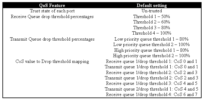
 Feedback