Decipher the RTP Stream for Packet Loss Analysis in Wireshark for Voice and Video Calls
Available Languages
Introduction
This document describes the process of how to decipher the Real-Time Streaming (RTP) stream for packet loss analysis in Wireshark for voice and video calls. You can use Wireshark filters in order to analyze simultaneous packet captures taken at or close-to the source and destination of a call. This is useful when you must troubleshoot audio and video quality issues when network losses are suspected.
Problem
This example uses this call flow:
IP phone A (central siteA) > 2960 switch > Router > WAN router (Central site) > IPWAN > WAN router(site B) > Router > 2960 > IP phone B
In this scenario, the problem encountered is that video calls from IP phone A to IP phone B result in bad video quality from central site A to branch site B where central has good quality but the branch side has issues.
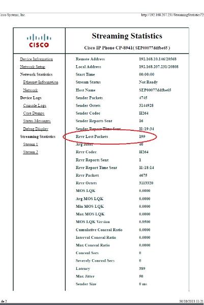
See the receiver lost packets in the streaming statistics of the branch IP phone:
Solution
Bad quality is seen only on the branch side and because the central site sees a good image, it looks like the stream from the central to the branch site seems to be losing packets over the network.
IP addressing scheme
Central IP phone: 192.168.10.146
Central Gateway: 192.168.10.253
Central WAN router: 192.168.10.254
Branch WAN router: 192.168.206.210
Branch Gateway: 192.168.206.253
Branch IP phone: 192.168.207.231
The packet captures are taken on the Central and Branch WAN router and the WAN drops these packets. Focus on the RTP stream from central IP phone (192.168.10.146) to branch IP phone (192.168.207.231). This stream misses packets on the branch WAN router if the WAN drops the packets on the stream from central WAN router to branch WAN router. Use the filter options in wireshark to isolate the problem:
- Open the capture in wireshark.
- Use the filter ip.src==192.168.10.146 && ip.dst==192.168.207.231. This filters out all UDP streams from central IP phone to branch IP phone.
- Perform the analysis on the branch side capture only but note you must perform these steps for the central capture as well.
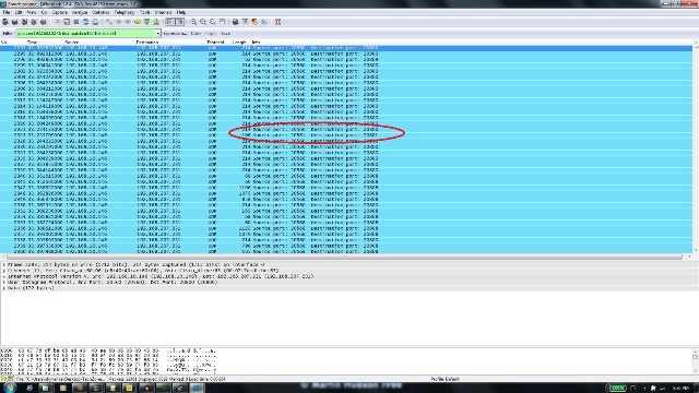
- In this screenshot, the UDP stream is filtered between the source and the destination IP addresses and contains two UDP streams (differentiated by the UDP port numbers). This is a video call so there are two streams: audio and video. In this example, the two streams are:
- Stream 1 : UDP source port : 20560, destination port : 20800
- Stream 2 : UDP source port : 20561, destination port : 20801
- Stream 1 : UDP source port : 20560, destination port : 20800
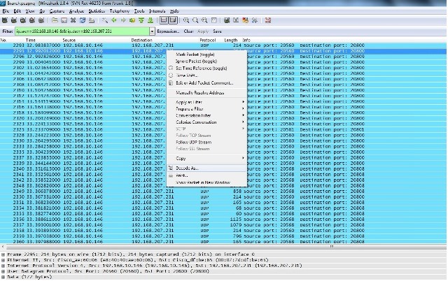
- Select a packet from one of the streams and right-click the packet.
- Select Decode As... and type RTP.
- Click Accept and Ok in order to decode the stream as RTP.
You are left with one stream decoded as RTP and the other as undecoded UDP.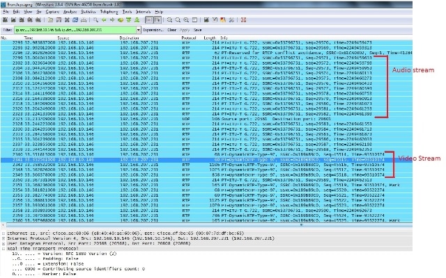
- Select a packet from the undecoded stream and decode it as RTP. This decodes both the audio and the video streams into RTP.
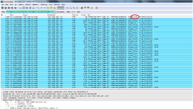
The problem is now only with video quality. Focus on the video RTP stream and use the UDP port numbers for this stream to filter out other streams. - View the port number by selecting one of the packets which displays the UDP port information on the bottom pane in the Wireshark utility. In the previous screenshot, one of the packets from the video stream is selected and you can see the Src Port (20568) and the Dst port (20808) information on the bottom pane.

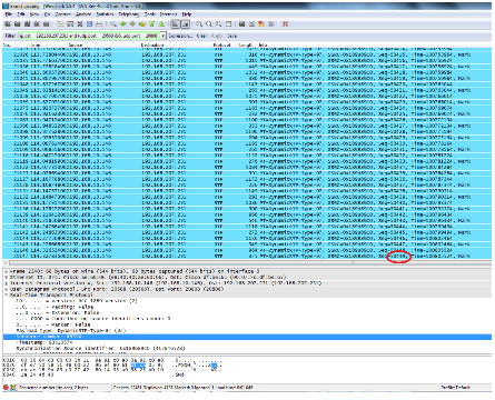
The first RTP sequence number is 45514 an the last is 50449 for the filtered out video RTP stream. - Make sure that the first and the last RTP sequence number packets are present in both captures.for example, central and branch captures) and note that the SSRC for the the stream would be the same on both the captures.
- Refine the filter to match only the packets between the first and the last RTP streams.
The sequence numbers are used to refine the stream in case the captures were not taken simultaneously, but with slight delay between them.
- Select a start and end sequence number. These packets are present in both the captures and refine the filter to display only those packets between the start and the end RTP sequence numbers. The filter for this is:
(ip.src==192.168.10.146 && ip.dst==192.168.207.231) && (udp.port eq 20568
 and udp.port eq 20808) && ( rtp.seq>=44514 && rtp.seq<=50449 )
When captures are simultaneously taken, no packets are missed at the start or end on both captures. If you see that one of the captures does not include a few packets at the start/end, use the first sequence number or the last sequence number in the capture missed in both packets to refine the filter for both the captures. Observe the packets that captured at both points between the same sequence numbers (RTP sequence number range).
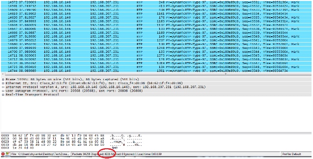
When you apply the filter, you see this at the central site and the branch site:
Central Site :
Branch site :
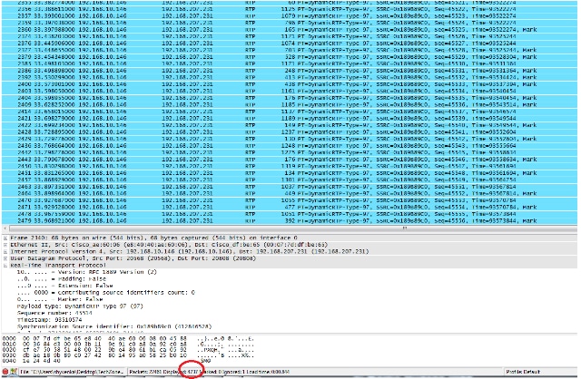
Note the filtered packet count at the bottom pane on the Wireshark utility on both captures. The Displayed count indicates the number of packets matching the desired filter criteria.
The central site has 4,936 packets that match the desired filter criteria between the start (45514) and end (50449) RTP sequence numbers while at the branch site there are only 4,737 packets. This indicates a loss of 199 packets. Note that these 199 packets match the "Rcvr Lost Pkts" count of 199 which was seen in the streaming statistics of the branch side IP phone shown at the start of this document.
This confirms that all the Rcvr Lost Packets were actually network losses dropped across the WAN. This is how the point of packet loss in the network is isolated while audio/video quality issues are handled involving suspected network drops.
Revision History
| Revision | Publish Date | Comments |
|---|---|---|
1.0 |
28-Jul-2014 |
Initial Release |


 Feedback