Cisco 6400 Universal Access Concentrator Frequently Asked Questions
Available Languages
Contents
Introduction
The Cisco 6400 carrier-class broadband aggregator is a high-performance, scalable service gateway that enables the selection and delivery of broadband network services, VPNs, and voice- and entertainment-driven traffic over the full suite of access media. The Cisco 6400 combines the richness of Cisco IOS® software, ATM switching and routing capabilities, and value-added service selection in a modular, scalable, redundant, Network Equipment Building Systems (NEBS) certified and a European Telecommunication Standards Institute (ETSI) form factor.
Q. What is a 6400 Universal Access Concentrator?
A. The Cisco 6400 Series Universal Access Concentrator (UAC) is a carrier-class service gateway allowing service providers to deploy value-added services as part of a next generation Internet access architecture. Thus, providers may converge on a single narrowband and broadband access architecture for access media (Digital Subscriber Line (DSL), cable, wireless, and dial).
The Cisco 6400 consists of a fault-tolerant midrange ATM switching core and multiple fault-tolerant routing engines.The Cisco 6400 enables this capability by combining both ATM switching and routing in a single scalable platform, drawing on the rich feature set of Cisco IOS software and the widely deployed Catalyst 8500 (former LightStream [LS]1010) and Cisco 7200 hardware. The ATM switch, based on Catalyst 8500 + Per-Flow Queuing (PFQ) technology, provides the necessary ATM switching and traffic management capabilities, while the router modules enable the service provider to offer scalable Layer 3 services. The Cisco 6400 is also one of the first Cisco products to combine full NEBS certification with redundancy.
Q. What functions does the Cisco 6400 UAC perform?
A. The Cisco 6400 acts as a single point of aggregation for access. Within a DSL deployment, users connect to DSL access multiplexers (DSLAMs) via the copper local loop. These DSLAMs then connect to the Cisco 6400 via ATM uplinks. Across this infrastructure, service providers have the option of deploying a number of different service models. The most basic is end-to-end virtual circuit connections (VCCs), where the user traffic remains within the ATM switching path of the Cisco 6400.
More sophisticated models include PPP tunneling, where user data is tunneled via Layer 2 Tunneling Protocol (L2TP) to a corporate or ISP home gateway. This scenario provides secure access to a provider. One may also terminate PPP sessions within the Cisco 6400, routing into an Internet core via the system's ATM or Fast Ethernet interfaces. This model also allows deployment of local content or cache servers within the point of presence (POP). In general, Cisco 6400 can provide an aggregate access chassis for broadband access architecture for access media (DSL, cable, wireless, and dial).
Q. Where will the Cisco 6400 UAC be deployed?
A. The Cisco 6400 will be deployed by two types of providers:
The first is the traditional telephony provider who controls the local copper loop, also known as an incumbent local exchange carrier (ILEC) in the U.S. These providers deploy DSLAMs in their central office and deploy the Cisco 6400 in the central office or within a Layer 3 POP, depending upon the environment. Note that the Cisco 6400, when performing PPP tunneling, is not considered to be routing in the traditional sense of the word.
Competitive Local Exchange Carriers (CLECs) (or ISPs) may deploy the Cisco 6400 in its POP, aggregating traffic from downstream DSLAMs controlled by ILECs. Note that CLECs can also operate DSLAMs if they have co-location rights and access to the local loop. ISPs and large corporations can deploy the Cisco 6400 as a home gateway at their sites.
In general, Cisco 6400 can provide an aggregate access chassis for broadband access architecture for access media (DSL, cable, wireless, and dial).
Q. What are the hardware components of the Cisco 6400 UAC?
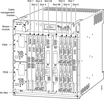
A. The Cisco 6400 uses a ten-slot, modular chassis featuring the option of half-height and full-height card and slot redundancy, along with dual, fault-tolerant, load-sharing AC or DC power supplies. The two central slots (slot 0A and 0B) in the Cisco 6400 are dedicated to redundant, field-replaceable node switch processor (NSP) modules that support the 5 Gbps shared memory, fully nonblocking switch fabric. The NSP also supports the feature card and high-performance reduced instruction set computing (RISC) processor that provides the central intelligence for the device. The NSP supports a variety of backbone and wide-area interfaces. The remaining slots support up to eight node route processors (NRPs), full-height node line cards (NLCs), or carrier modules for half-height NLCs. NRPs and NLCs can be configured for redundant operation. As a result, you can have multiple redundant pairs of NRPs and NLCs, or any combination of nonredundant NRPs and NLCs. The NRPs are fully functional router modules capable of terminating PPP sessions delivered over OC-12, OC-3, or DS3 node line cards.
Figure 1: A Typical Fully Loaded Cisco 6400 Chassis

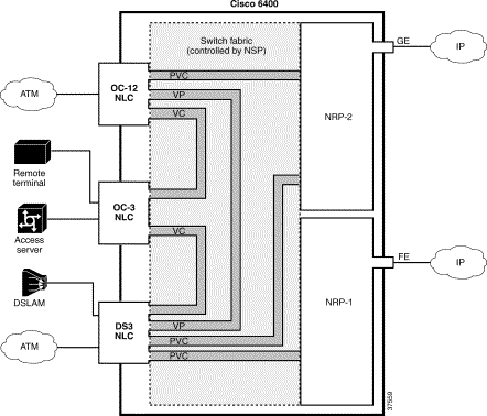
Figure 2: Simple Schematic of Cisco 6400 Internal and External Connectivity

The Cisco 6400 NSP provides ATM switching functionality. The NSP uses permanent virtual circuits (PVCs) or permanent virtual paths (PVP) to direct ATM cells between the NRP and ATM interface. The NSP also controls and monitors the Cisco 6400 system, including component NLCs and NRPs.
Cisco 6400 supports three NRPs, designated as NRP-1, NRP-2, and NRP-2SV:
NRP-1—Incorporates a 100 Mbps Fast Ethernet interface for connecting into an IP network and has the processing capability for OC-3 rate of user traffic.
NRP-2 and NRP-2SV—Provides a Gigabit Ethernet interface and sufficient processing capability for handling the OC-12 rate of user traffic.
The Cisco 6400 can contain multiple NRP modules, configured to operate independently or as 1+1 redundant pairs. The NRP receives traffic from NLC interface ports through the NSP ATM switch, reassembles the ATM cells into packets, processes (for example, routes or bridges) the packets, and then performs one of the following:
Segments the packets into ATM cells and sends them back to the NSP for transmission out of another NLC interface; or
Sends the traffic out the Fast Ethernet (NRP-1) or Gigabit Ethernet (NRP-2) interface.
Table 1 below shows differences between NRP-1 and NRP-2 or NRP-2SV.
Table 1
Feature or Capability NRP-1 NRP-2 and NRP-2SV Session Scalability Hardware supports as many as 2000 sessions per NRP-1. Hardware supports as many as 16,000 sessions per NRP-2. Physical Interfaces Faceplate interfaces: Backplane interfaces:
Console port
Auxiliary port
Ethernet port
Fast Ethernet port
155 Mbps ATM interface
Backplane Ethernet (BPE)
Faceplate interfaces: Backplane interfaces:
Gigabit Ethernet interface
622 Mbps ATM interface
Port adapter modules (PAM) mailbox serial interface. (The PAM mailbox serial interface is used for internal system communication. Do not attempt to configure serial interfaces on the Cisco 6400.)
Location of Startup Configurations and Crash Information NRP-1 memory (built-in or internal Flash). Personal Computer Memory Card International Association (PCMCIA) disk on NSP. Message Logging Messages are logged on the NRP-1 as a local message. NRP-2 messages are logged on both the NSP and NRP-2. NRP-2 messages on the NSP include the NRP-2 slot number. Console Line Access Direct external connection to NRP-1 console port or auxiliary port. Indirect external connection via the NSP. NSP contains a virtual communication server to access NRP-2 console. ROM Monitor (ROMMON) ROMMON not upgradable; NRP-1 ROM state information stored locally on NRP-1. ROMMON is upgradable; NRP-2 ROM state information is stored on the NSP PCMCIA disk. Simple Network Management Protocol (SNMP) Standard SNMP services. Standard SNMP services, or the NSP can be used as the proxy forwarder. LED Display None On the faceplate. Cisco (NLCs) provide ATM interfaces for the Cisco 6400 system and are controlled by the NSP. The three types of NLCs available for the Cisco 6400 offer different interface types, as shown in Table 2.
Table 2
NLC Bandwidth Cable Height Number of Ports OC-12/STM-4 622 Mbps SONET single-mode fiber-optic cable Full-height 1 OC-3/STM-1 SM 155 Mbps SONET single-mode fiber-optic cable Half-height 2 OC-3/STM-1 MM 155 Mbps SONET multimode fiber-optic cable Half-height 2 DS3 45 Mbps Coaxial cable Half-height 2 For a detailed description about Cisco 6400 supported NLCs, refer to Cisco 6400 Node Line Card Frequently Asked Questions.
Q. How many users will the Cisco 6400 UAC support?
A. Cisco 6400 NRP-1 will support a minimum 2000 users (PPP terminations) per NRP, yielding a maximum of 14,000 per Cisco 6400. (two slots 0A, and 0B for NSP; one slot for access users, and remaining seven slots fully loaded with NRP-1). This is in addition to a maximum of 32,000 end-to-end ATM VCCs when used for ATM pass-through. Cisco NRP-2 and NRP-2SV support a minimum of 16,000 users (PPP terminations), yielding a maximum of 112,000 user sessions per Cisco 6400 (two slots 0A, and 0B for NSP; one slot for access users, and remaining seven fully loaded with NRP-1).
Q. What is a typical hardware configuration?
A. A typical Cisco 6400 hardware configuration includes an NSP, multiple NRPs, and multiple NLCs. For example, a nonredundant system servicing 14,000 users (combination of 1483 bridge, PPP session, or tunnel) includes 1xNSP, 7xNRP, and 2xNLC (yielding four ATM interfaces). Two of the ATM interfaces terminate at downstream DSLAMs, while two terminate at ATM switches in the service provider's core.
Related Information
- Cisco DSL Technical Support Pages
- Cisco IOS Error Message Decoder ( registered customers only)
- Cisco IOS Output Interpreter ( registered customers only)
- Technical Support - Cisco Systems
Revision History
| Revision | Publish Date | Comments |
|---|---|---|
1.0 |
01-Jun-2005 |
Initial Release |


 Feedback