Introduction
This document describes common configuration issues seen in Cisco CG522-E and P-5GS6-GL Modules.
Prerequisites
Requirements
Cisco recommends that you have basic knowledge of these topics:
- 5G Cellular Network Basics
- Cisco Cellular Gateway 522-E
- Cisco P-5GS6-GL module
- Cisco IOS® XE and Cisco IOS® CG
Components Used
The information in this document is based on these software and hardware versions:
- Cisco Cellular Gateway 522-E with IOS® CG version 17.9.3a.
- Cisco IR1101 with IOS® XE version 17.9.3 with a P-5GS6-GL module plugged in.
This applies to a P-5GS6-GL module connected to a router in standalone mode, or a CG522-E in standalone or controller mode managed by SD-WAN. This document does not apply to a P-5GS6-GL module connected to a router in SD-WAN since command syntax is different.
The information in this document was created from the devices in a specific lab environment. All of the devices used in this document started with a cleared (default) configuration. If your network is live, ensure that you understand the potential impact of any command.
Background information
5G technology is the fifth generation of cellular networks. It comes with a set of beneficial features, such as new theorical throughput of almost 10 gigabytes per second, lower latency, better client data traffic so more users can be handled simultaneously while the network is used, and less battery consumption for mobile devices.
Today, more countries allow its usage, providers offer a network plan which includes it, and a high variety of devices support it. This has caused its implementation in different fields. For example, ambulances use it for remote communication, in stadiums a high number of clients connect without service loss, industries interconnect their locations, and people access to internet in their mobile phones.
Due to this broad adoption of 5G, Cisco has innovated with industrial devices capable of getting attached to it. The importance of understanding and configuring 5G Cisco products is imperative. Throughout this document, common issues are presented while their configuration related from physical to sotware conditions.
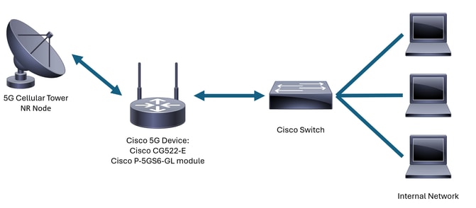
It is expected to have a connection from Cisco 5G device to the 5G New Radio (NR) Node which is also called a 5G Cellular Tower, so communication in 5G can happen:
Common Issues either for a CG522-E or a P-5GS6-GL Module Connected to a Router
Device not Attached to 5G Band
- Ensure with the carrier that the acquired network plan is activated for 5G band.
- Confirm with the carrier about 5G coverage area in the zone the 5G device is placed.
Confirm the Device Detects the SIM
For a CG522-E:
CellularGateway#show cellular 1 sim
Cellular Dual SIM details:
SIM O = Present
SIM 1 = Not Present
Active SIM = O  -------> Slot 0 is Active
For a P-5GS6-GL module connected to a router:
isr#show controller cellular 0/X/0 detail
Interface Cellular0/2/0
              *
              *
Cellular Dual SIM details:
---------------------------
SIM 0 is present
SIM 1 is not present
SIM 0 is active SIM
Confirm the Device Actively Uses Required SIM
For a CG522-E:
CellularGateway#show cellular 1 sim
Cellular Dual SIM details:
SIM O = Present
SIM 1 = Present
Active SIM = O  -------> Slot 0 is Active
For a P-5GS6-GL module connected to a router:
isr#show controller cellular 0/X/0 detail
Interface Cellular0/2/0
              *
              *
Cellular Dual SIM details:
---------------------------
SIM 0 is present
SIM 1 is not present
SIM 0 is active SIM
Verify the IMSI and IMEI are Read from the SIM
For a CG522-E:
CellularGateway#show cellular 1 hardware
Modem Firmware Version = SWIX55C_01.07.08.00 000000 jenkins
Device Model ID = EM9190
International Mobile Subscriber Identity (IMSI) = XXXXXXXXXXXXXXX
International Mobile Equipment Identity (IMEI) = XXXXXXXXXXXXXXX
Integrated Circuit Card ID (ICCID) = XXXXXXXXXXXXXXXXXXXX
Mobile Subscriber Integrated Services Digital Network-Number (MSISDN) = XXXXXXXXXX
              *
              *
For a P-5GS6-GL module connected to a router:
isr#show cellular 0/X/0 all
Hardware Information
====================
Modem Firmware Version = M0H.020202
Host Firmware Version = A0H.000292
Device Model ID = FN980
International Mobile Subscriber Identity (IMSI) = XXXXXXXXXXXXXXX
International Mobile Equipment Identity (IMEI) = XXXXXXXXXXXXXXX
Integrated Circuit Card ID (ICCID) = XXXXXXXXXXXXXXXXXXXX
Mobile Subscriber Integrated Services
Digital Network-Number (MSISDN) = XXXXXXXXXX
              *
              *
Confirm the Configured APN is the Correct One
- Each carrier uses a specific Access Point Name (APN) which is provided when the cellular line is acquired. It depends on the contracted service whether you get a dynamic, static, or custom IP/service. The APN must be used so the device is attached to the cellular network.
For a CG5222-E, with the command show cellular 1 profile the configured APNs can be seen. A profile must be in Active state, which means it is attached:
CellularGateway#show cellular 1 profile
PROFILE ID   APN           PDP TYPE     STATE  AUTHENTICATION  USERNAME  PASSWORD
-----------------------------------------------------------------------------------
1             IMS           IPv4        ACTIVE  none            -         -
For a P-5GS6-GL module connected to a router, with the command show cellular 0/X/0 profile, the same information is shown:
isr#show cellular 0/X/0 profile
Profile password Encryption level =  7
Profile 1 = INACTIVE **
--------
PDP Type = IPv4v6
Access Point Name (APN) = ims
Authentication = None

Profile 2 = INACTIVE
--------
PDP Type = IPv4v6
Access Point Name (APN) = vzwadmin
Authentication = None

Profile 3 = ACTIVE*
--------
PDP Type = IPv4v6
PDP address = XXX.XXX.XXX.XXX
IPv4 PDP Connection is successful
Access Point Name (APN) = VZWINTERNET
Authentication = None
    Primary DNS address = XXX.XXX.XXX.XXX
    Secondary DNS address = XXX.XXX.XXX.XXX

Profile 4 = INACTIVE
--------
PDP Type = IPv4v6
Access Point Name (APN) = vzwapp
Authentication = None

Profile 5 = INACTIVE
--------
PDP Type = IPv4v6
Access Point Name (APN) =
Authentication = None

Profile 6 = INACTIVE
--------
PDP Type = IPv4v6
Access Point Name (APN) = vzwclass6
Authentication = None

  * - Default profile
 ** - LTE attach profile
Confirm the Device is Attached to 5G Band
- For a CG522-E with 17.9.3 and above, this command reports when the device is connected to 5G technology:
CellularGateway#show cellular 0 radio
              *
              *
Network Change Event = activated 5G ENDC
Verify Radio Values
- Refer to these reference values and corroborate the device is within them:
- Received Signal Strength Indication (RSSI) – Look for a value greater than -80 dBm (for example, -79 is greater than -80).
- Received Signal Reference Power (RSRP) – Look for a value greater than -105 dBm (for example, -104 is greater than -105).
- Reference Signal Received Quality (RSRQ) – Look for a value greater than -12 dB (for example, -11 is greater than -12).
- Signal to Noise Ratio (SNR) or Interference – Look for a value greater than 5 dB (for example, 6 is better than 5).

Note: These values must not be 0.
- Here is an example of good values:
For a CG522-E:
CellularGateway#show cellular 0 radio
              *
              *
Current Band = LTE
Current RSSI = -56 dBm
Current RSRP = -72 dBm
Current RSRQ = -6 dB
Current SNR = 12.4 dB
              *
              *
For a P-5GS6-GL module connected to a router:
isr#show cellular 0/X/0 radio
              *
              *
Current RSSI = -42 dBm
Current RSRP = -99 dBm
Current RSRQ = -5 dB
Current SNR = 10.6 dB
              *
              *
If these values are not within the mentioned ranges, confirm that:
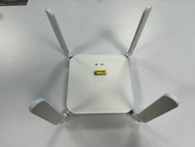
- All antennas are correctly installed. For a CG522-E:
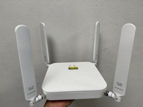
- The antennas are correctly directed and point to the sky. For a CG522-E:
- In the case of a P-5GS6-GL module connected to a router, refer to 5G Sub-6 GHz Pluggable Interface Module, section Attaching an Antenna.
- There are no interferences such as microwaves, radars, and so on, where the device is placed.
Common Issues only for a CG522-E
CG522-E does not Power Up when PoE is Used
Verify that the device is PoE capable; in the ethernet port, a label with a lightning symbol must be present:
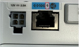

Note: If a non-PoE unit is replaced, the same one is received.
Copy Upgrade Files to a CG522-E with Common TFTP Servers is not Successful
In this case, a switch can be used to make it act as the TFTP server. This workaround is for software and firmware upgrades.
1. In the switch, copy the file(s) to its flash, then enable it as TFTP:
tftp-server flash:<filename>.nvu
tftp-server flash:<filename>.cwe
2. In some cases, a USB connected to the switch can also be used as path:
tftp-server usbflash0:<filename>.nvu
tftp-server usbflash0:<filename>.cwe
3. Then, in the CG, copy the files as usual:
gw-action:request file download tftp://<tftp_ip_address>/<filename>.nvu create_dir fw_upgrade_add
gw-action:request file download tftp://<tftp_ip_address>/<filename>.cwe create_dir fw_upgrade_add
Firmware Upgrade to a Newer Version when the CG522-E is Initially in 1.7.8
By default, most CGs contain 1.7.8 as firmware version. If an upgrade is required, first go to 1.7.13, and then to the desired version.
With the command show cellular 1 hardware the current firmware version is shown:
CellularGateway#show cellular 1 hardware
Modem Firmware Version = SWIX55C_01.07.08.00 000000 jenkins
              *
              *
Specific Firmware for the Device
- In some specific cases, a service provider requires specific firmware to be installed in a CG522-E, if that applies:
- Use the command show cellular 1 hardware to identify the Device Model ID:
CellularGateway#show cellular 1 hardware
Modem Firmware Version = SWIX55C_01.07.08.00 000000 jenkins
Device Model ID = EM9190
              *
              *
- Go to Cisco Software Downloads and select the correct model ID:
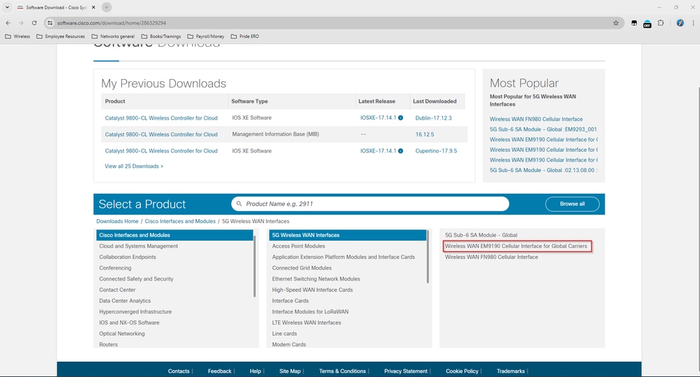
- Go to Cellular Modem Firmware.
- Look for the required firmware. Both .cwe and .nvu files are used in the upgrade.
Common Issues only for P-5GS6-GL Modules Connected to a Router
Module does not Automatically Connect to 5G after Reload
- A dialer in this platform is used to initiate the connection and checks if it remains Up to the carrier. When the dialer is properly configured, this output is shown:
isr#show dialer
Ce0/1/0 - dialer type = DIALER CWAN
Idle timer (never), Fast idle timer (20 secs)
Wait for carrier (30 secs), Re-enable (15 secs)
Dialer state is data link layer up
Dial reason: Dialing on watched route loss
Time until disconnect never
Current call connected 00:06:10
Connected to lte

Dial String      Successes   Failures    Last DNIS   Last status
lte                      1          0    00:06:10       successful Default
- Ensure the dialer is configured as stated in the Official Configuration Guide section Configure Cellular Interface with dialer watch-group. The used IP address must be a dummy non-routable one.
CLI Flooded by Carrier Aggregation Logs
Cisco has identified that when the carrier that the module is attached to uses Carrier Aggregation, the CLI of the IR1XXX router gets flooded with these logs:
Apr  5 23:53:17.057: %CELLWAN-2-NC_EVENT2: Cellular0/4/0: Network change event - activated 4G Carrier Aggregation.
Apr  5 23:53:46.502: %CELLWAN-2-NC_EVENT2: Cellular0/4/0: Network change event - activated 4G Carrier Aggregation.
However, this does not have any effects on functionality or performance and the behavior is tracked via Cisco bug ID CSCwb47658.


 Feedback