Understand NFVIS Virtual Networks: OVS, DPDK and SR-IOV
Available Languages
Download Options
Bias-Free Language
The documentation set for this product strives to use bias-free language. For the purposes of this documentation set, bias-free is defined as language that does not imply discrimination based on age, disability, gender, racial identity, ethnic identity, sexual orientation, socioeconomic status, and intersectionality. Exceptions may be present in the documentation due to language that is hardcoded in the user interfaces of the product software, language used based on RFP documentation, or language that is used by a referenced third-party product. Learn more about how Cisco is using Inclusive Language.
Contents
Introduction
This document describes the virtual networking scheme that the NFVIS platform provides for communicating VNFs in enterprise and service networks.
Components Used
The information in this document is based on these hardware and software components:
- ENCS5412 running NFVIS 4.7.1-FC4
- c8300 uCPE 1N20 running NFVIS 4.12.1-FC2
The information in this document was created from the devices in a specific lab environment. All of the devices used in this document started with a cleared (default) configuration. If your network is live, ensure that you understand the potential impact of any command.
Overview of networking in NFVIS
An internal management network (int-mgmt-net) and bridge (int-mgmt-br) are internally used for VNF monitoring, assigning management IP addresses from the 10.20.0.0/24 subnet.
ENCS54XX Platform
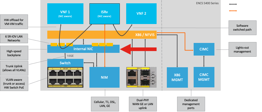
Figure 1. Hardware Switch and WAN/LAN Uplink NICs Internal Connections
Catalyst 8200 uCPE
-
NFVIS can be accessed by default through the WAN port or GE0/2 LAN port for management.
-
WAN network (wan-net and wan2-net) and WAN bridge (wan-br and wan2-br) are set to enable DHCP by default. GE0-0 is associated to WAN bridge and GE0-1 with WAN2 bridge by default.
-
The management IP address 192.168.1.1 on the Catalyst 8200 UCPE is accessible through GE0-2.
-
GE0-2 is associated to LAN bridge.
-
An internal management network (int-mgmt-net) and bridge (int-mgmt-br) is created and internally used for system monitoring.
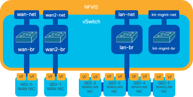
Figure 2. Internal bridging and virtual switches assigned to the 8200 NICs
Catalyst 8300 uCPE 1N20
1. NFVIS can be accessed by default via the FPGE (Front Panel Gigabit Ethernet)WAN portsor via the GE0-2 LAN port forManagement
2. WAN network (wan-net) and a WAN bridge (wan-br) is set by default to enable DHCP. GE0-0 is by default associated to WAN bridge
3. WAN network (wan2-net) and a WAN bridge (wan2-br) is created by default but not associated with any physical ports
4. GE0-2 is associated to LAN bridge, all other ports are not associated with OVS
5. The Management IP 192.168.1.1 on C8300-uCPE is accessible via GE0-2
6. An internal management network (int-mgmt-net) and a bridge (int-mgmt-br) is created and is internally used for system monitoring.
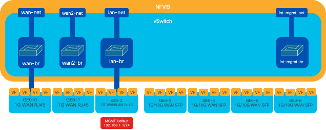
Figure 3. Internal bridging and virtual switches assigned to the 8300 NICs
Networking Virtualization Technologies
Open vSwitch (OVS)
Open vSwitch (OVS) is an open-source, multi-layer virtual switch designed to enable network automation through programmatic extensions, while providing support for standard management interfaces and protocols, such as NetFlow, sFlow, IPFIX, RSPAN, CLI, LACP, and 802.1ag. Its widely used in large virtualized environments, particularly with hypervisors to manage network traffic between virtual machines (VMs). It allows for the creation of sophisticated network topologies and policies directly managed through the NFVIS interface, providing a versatile environment for network function virtualization.
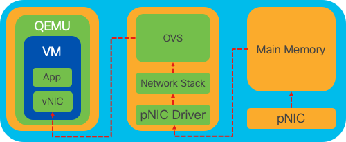
Figure 4. OVS configuration within the Linux kernel
OVS Bridges
It uses virtual network bridges and flows rules to forward packets between hosts. It behaves like a physical switch, only virtualized.

Figure 5. Example implementation of 2 VMs or VNFs attached to the wan-br bridge
Context Switching Deficits
When a network packet arrives at a network interface card (NIC), it triggers an interrupt, a signal to the processor indicating that it needs immediate attention. The CPU pauses its current tasks to handle the interrupt, a process known as interrupt processing. During this phase, the CPU, under the control of the operating system kernel, reads the packet from the NIC into memory and decides the next steps based on the packet destination and purpose. The goal is to quickly process or route the packet to its intended application, minimizing latency and maximizing throughput.
Context switching is the process by which a CPU switches from executing tasks in one environment (context) to another. This is particularly relevant when moving between user mode and kernel mode:
-
User Mode: This is a restricted processing mode where most applications run. Applications in user mode do not have direct access to hardware or reference memory and must communicate with the operating system kernel to perform these operations.
-
Kernel Mode: This mode grants the operating system full access to the hardware and all memory. The kernel can execute any CPU instruction and reference any memory address. Kernel mode is required for performing tasks like managing hardware devices, memory, and executing system calls.
When an application needs to perform an operation that requires kernel-level privileges (such as reading a network packet), a context switch occurs. The CPU transitions from user mode to kernel mode to execute the operation. Once completed, another context switch returns the CPU to user mode to continue executing the application. This switching process is critical for maintaining system stability and security but introduces overhead that can affect performance.
OVS mainly runs in the operating system user space, which can become a bottleneck as data throughput increases. This is because more context switches are needed for the CPU to move to kernel mode to process packets, slowing down performance. This limitation is particularly noticeable in environments with high packet rates or when precise timing is crucial. To address these performance limitations and meet the demands of modern, high-speed networks, technologies like DPDK (Data Plane Development Kit) and SR-IOV (Single Root I/O Virtualization) were developed.
Data Plane Development Kit (DPDK)
DPDK is a set of libraries and drivers designed to accelerate packet processing workloads on a wide range of CPU architectures. By bypassing the traditional kernel networking stack (avoiding context switching), DPDK can significantly increase data plane throughput and reduce latency. This is particularly beneficial for high-throughput VNFs that require low-latency communication, making NFVIS an ideal platform for performance-sensitive network functions.

Figure 6. Traditional OVS (left-hand side) and DPDK OVS (right-hand side) context switching optimizations
Support for DPDK for OVS started in NFVIS 3.10.1 for ENCS and 3.12.2 for other platforms.
- Service Chain throughput near SRIOV, better than non-DPDK OVS.
- Virtio driver required for VNF.
- Supported platforms:
- ENCS 3.10.1 onwards.
- UCSE, UCS-C, CSP5K 3.12.1 onwards.
- DPDK for port-channels supported since 4.12.1.
- Packet /traffic capture : Not supported in DPDK.
- Span traffic on PNIC : Not supported in DPDK.
- After OVS-DPDK is enabled, it cannot be disabled as an individual feature. Only way to disable DPDK would be a factory reset.
Data Copying
Traditional networking approaches often require that data be copied multiple times before reaching its destination in the VM memory. For example, a packet must be copied from the NIC to the kernel space, then to the user space for processing by a virtual switch (like OVS), and finally to the VM memory. Each copy operation incurs a delay and increases CPU utilization despite the performance improvements DPDK offers by bypassing the kernels networking stack.
These overheads include memory copies and the processing time needed to handle packets in user space before they can be forwarded to the VM. PCIe Passthrough and SR-IOV addresses these bottlenecks by allowing a physical network device (like a NIC) to be shared directly among multiple VMs without involving the host operating system to the same extent as traditional virtualization methods.
PCIe Passthrough
The strategy involves bypassing the hypervisor to allow Virtual Network Functions (VNFs) direct access to a Network Interface Card (NIC), achieving nearly maximum throughput. This approach is known as PCI passthrough, which lets a complete NIC be dedicated to a guest operating system without the intervention of a hypervisor. In this setup, the virtual machine operates as though its directly connected to the NIC. For instance, with two NIC cards available, each one can be exclusively assigned to different VNFs, providing them direct access.
However, this method has a drawback: if only two NICs are available and exclusively used by two separate VNFs, any additional VNFs, such as a third one, would be left without NIC access due to the lack of a dedicated NIC available for it. An alternative solution involves using Single Root I/O Virtualization (SR-IOV).
Single Root I/O Virtualization (SR-IOV)
Is a specification that allows a single physical PCI device, like a network interface card (NIC), to appear as multiple separate virtual devices. This technology provides direct VM access to physical network devices, reducing overhead and improving I/O performance. It works by dividing a single PCIe device into multiple virtual slices, each assignable to different VMs or VNFs, effectively solving the limitation caused by a finite number of NICs. These virtual slices, known as Virtual Functions (VFs), allow for shared NIC resources among multiple VNFs. The Physical Function (PF) refers to the actual physical component that facilitates SR-IOV capabilities.
By leveraging SR-IOV, NFVIS can allocate dedicated NIC resources to specific VNFs, ensuring high performance and low latency by facilitating Direct Memory Access (DMA) of network packets directly into the respetive VM memory. This approach minimizes CPU involvement to merely processing the packets, thus lowering CPU usage. This is especially useful for applications that require guaranteed bandwidth or have stringent performance requirements.

Figure 7. NFVIS SR-IOV PCIe Resources Separation through Hardware Functions
Physical Functions (PFs)
They are full-featured PCIe functions and refer to a purpose-built hardware box that provides specific networking function; these are fully featured PCIe functions that can be discovered, managed, and manipulated like any other PCIe device. Physical functions include the SR-IOV capabilities that can be used to configure and control a PCIe device.
Virtual Functions (VFs)
They are streamlined functions with minimal configuration resources (lightweight), focusing solely on processing I/O as simple PCIe functions. Every Virtual Function originates from a Physical Function. The device hardware limits the possible number of Virtual Functions. One Ethernet port, the Physical Device, can correspond to numerous Virtual Functions, which can then be allocated to different virtual machines.
Recomended Drivers for SR-IOV Accelaration on NFVIS Capable Hardware
| Platform | NIC(s) | NIC Driver |
| ENCS 54XX | Backplane Switch | i40e |
| ENCS 54XX | GE0-0 and GE0-1 | igb |
| Catalyst 8200 uCPE | GE0-0 and GE0-1 | ixgbe |
| Catalyst 8200 uCPE | GE0-2 and GE0-5 | igb |
Use Cases for DPDK and SR-IOV
DPDK Preference
Particularly in scenarios where network traffic flows primarily east-west (meaning it stays within the same server), DPDK outperforms SR-IOV. The rationale is straightforward: when traffic is managed internally within the server without needing to access the NIC, SR-IOV does not provide any benefit. In fact, SR-IOV could potentially lead to inefficiencies by unnecessarily extending the traffic path and consuming NIC resources. Therefore, for internal server traffic management, leveraging DPDK is the more efficient choice.
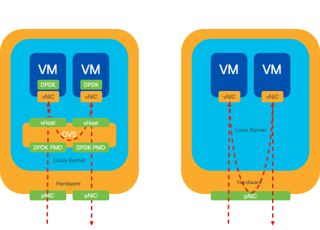
Figure 8. DPDK and SR-IOV Packet Traversal in East-to-West Traffic
SR-IOV Preference
In situations where network traffic flows from north to south, or even east to west but specifically between servers, using SR-IOV proves to be more advantageous than DPDK. This is particularly true for server-to-server communication. Given that such traffic inevitably has to traverse the NIC, opting for DPDK-enhanced OVS could unnecessarily introduce additional complexity and potential performance constraints. Therefore, SR-IOV emerges as the preferable choice in these circumstances, offering a straightforward and efficient pathway for handling inter-server traffic.
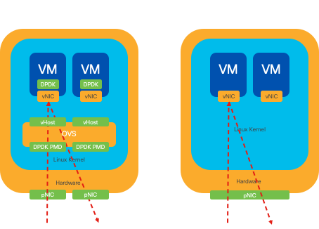
Figure 9. DPDK and SR-IOV Packet Traversal in North-to-South Traffic

Tip: Remember, its possible to enhance the performance of an SR-IOV-based setup by integrating SR-IOV with DPDK within a Virtual Network Function (VNF), excluding the scenario where DPDK is used in conjunction with OVS as previously described.
Configuration
Enabling DPDK
To enable DPDK from the GUI, you must need to navigate to Configuration > Virtual Machine > Networking > Networks. Once you are on the menu, click on the switch to activate the feature
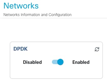
Figure 10. Slide Button Available on the GUI for DPDK Activation
For the CLI, you must enable it from the global system settings in configuration mode.
nfvis(config)# system settings dpdk enable
Caution: DPDK cannot be disabled unless a factory-reset is performed from NFVIS.
Create a new Network and Associate it to a new OVS Bridge
Navigate to Configuration > Virtual Machine > Networking > Networks. Once you are on the Networks page, click on the top left plus sign (+) for the Networks table,

Figure 11. Networks Table View from the NFVIS GUI
Name the network and associate to a new bridge. VLAN and Interface bind options can depend on the network infrastructure needs.
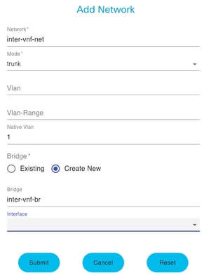
Figure 12. "Add Network" Modal for Creating Virtual Networks in the NFVIS GUI
After clicking the submit button, you must be able to review the newly created network appended to the Networks table.

Figure 13. Networks Table View from the NFVIS GUI where the "Refresh Icon" is on the Top Right Corner (Highlighted in Red)

Note: If the new network is not observed on the table, please click the top right refresh button or refresh the entire page.
If performed within from the CLI, every network and bridge is created from configuration mode, the workflow is the same as the GUI version.
1. Create the new bridge.
nfvis(config)# bridges bridge inter-vnf-br2
nfvis(config-bridge-inter-vnf-br2)# commit
2. Create a new Network and associate it to the previously created bridge
nfvis(config)# networks network inter-vnf-net2 bridge inter-vnf-br2 trunk true native-vlan 1
nfvis(config-network-inter-vnf-net2)# commit
Connecting VNFs
To start with a network topology or single VFN deployment, you must navigate to Configuration > Deploy. You can drag a VM or Container from the selection list to the topology crafting area to start creating your virtualized infrastructure.
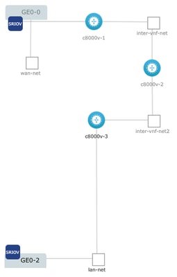
Figure 14. Example deployment were c8000v-1 is connected Ge0-0 SR-IOV passthrough and a customized OVS inter-vnf network, c8000v-2 has 2 OVS connections that communicate it with c8000v-1 and c8000v-3, and c8000v-3 has 1 OVS intra-vnf connection that permits communication with c8000v-2 as well as a exit interface through the Ge0-2 LAN port bridge (OVS).
Where same topology from the image can be created from CLI:
c8000v-1 Configuration:
nfvis(config)# vm_lifecycle tenants tenant admin deployments deployment c8000v-1 vm_group c8000v-1 image c8000v-universalk9_16G_serial.17.09.04a.tar.gz flavor C8000V-small
nfvis(config-vm_group-c8kv_group)# interfaces interface 0 network GE0-0-SRIOV-1
nfvis(config-interface-0)# exit
nfvis(config-vm_group-c8kv_group)# interfaces interface 1 network inter-vnf-net
nfvis(config-interface-1)# exit
nfvis(config-vm_group-c8kv_group)# port_forwarding port ssh protocol TCP vnf_port 22 external_port_range 2228 2228
nfvis(config-external_port_range-2228/2228)# commit
c8000v-2 Configuration:
nfvis(config)# vm_lifecycle tenants tenant admin deployments deployment c8000v-2 vm_group c8000v-2 image c8000v-universalk9_16G_serial.17.09.04a.tar.gz flavor C8000V-small
nfvis(config-vm_group-c8kv_group)# interfaces interface 0 network inter-vnf-net
nfvis(config-interface-0)# exit
nfvis(config-vm_group-c8kv_group)# interfaces interface 1 network inter-vnf-net2
nfvis(config-interface-1)# exit
nfvis(config-vm_group-c8kv_group)# port_forwarding port ssh protocol TCP vnf_port 22 external_port_range 2229 2229
nfvis(config-external_port_range-2229/2229)# commit
c8000v-3 Configuration:
nfvis(config)# vm_lifecycle tenants tenant admin deployments deployment c8000v-3 vm_group c8000v-3 image c8000v-universalk9_16G_serial.17.09.04a.tar.gz flavor C8000V-small
nfvis(config-vm_group-c8kv_group)# interfaces interface 0 network inter-vnf-net2
nfvis(config-interface-0)# exit
nfvis(config-vm_group-c8kv_group)# interfaces interface 1 lan-net
nfvis(config-interface-1)# exit
nfvis(config-vm_group-c8kv_group)# port_forwarding port ssh protocol TCP vnf_port 22 external_port_range 2230 2230
nfvis(config-external_port_range-2230/2230)# commit
Related Articles and Documentation
Revision History
| Revision | Publish Date | Comments |
|---|---|---|
1.0 |
14-Feb-2024 |
Initial Release |
Contributed by Cisco Engineers
- Sebastian MadrigalTechnical Consulting Engineer
Contact Cisco
- Open a Support Case

- (Requires a Cisco Service Contract)
 Feedback