Table of Contents
1: Route Processor (RP-E) Universal Serial Bus (USB) Boot Procedure using Basic Input/Output System (BIOS) Menu (To be followed till CSCvm77427  is fixed)
2: Standby RP-E Bringup (To be followed till CSCvk33106  is fixed)
3: LC Bringup (if required)
1. RP-E USB Boot Procedure using BIOS Menu
Please note, this procedure is applicable from release 6.3.1 onwards (where RP-E support was introduced).
This is not specific to any chassis type, but is relevant to RP-E specific chassis, for example, any modular chassis like 5504, 5508, 5516 with RP-E.
Also, not applicable for fixed platforms.
Step 1: Prepare the USB with image using this procedure
Step 2: Also verify the MD5 of the files to make sure the contents are the same.
Step 3: In a single RP system which has the USB inserted, perform a power cycle.
Step 4:Press Escape to break into the BIOS menu. We should see something like below.

Step 5: Select “Boot Manager” option and press Enter.

Step 6: Select UEFI: Built-in Shell option from the below Menu

Step 7: Either press any key to drop to the Shell> prompt or by default, the console will drop to the Shell prompt.
** Please note that delete/backspace doesn’t work here. If anything incorrect is typed, do not hesitate to press Enter, since it doesn’t impact the current procedure.
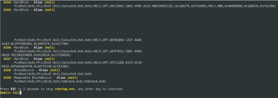
Step 8: Type “fs1:” and press Enter
** Please pay attention to which slot the USB is inserted in, based on which, the below file system could vary - between fs0 and fs1) **
In this example, the USB is inserted in slot1.

Step 9: Type “ls” to list the contents of “boot” and “EFI” (Entire snapshot is provided below)
Step 10: cd EFI
Step 11: ls
Step12: cd boot

Step 13: Upon listing the contents, we should be seeing grub.cfg and bootx64.efi
Step 14: Type “bootx64.efi” and press enter. (Tab works to auto complete)

Step 15: Based on the above log, RP-E is booting from the USB.
Step 16: Once the RP comes up, configure the username/password and follow the remaining steps.
2. Standby RP-E Bringup
Step 1: Insert the standby RP-E into the system (In this example, RP1 has been inserted)
Step 2: This step depends on the state of the standby RP-E. Please follow whichever is applicable.
Note: Spare RP will be shipped with the latest image by default, if there is no image picked by placing the order.
In order to sync it with the active RP-E, execute the below command from RP0 sysadmin, once the standby is detected in the inventory.
Execute the below command from RP0 sysadmin to bring up the standby RP.
sysadmin-vm:0_RP0# hw-module location 0/RP1 bootmedia network reload
One can monitor the console of RP1 to make sure internal PXE has triggered. This should bring up the standby RP.
Note: If image is corrupted/deleted from Standby RP-E it syncs with Active RP or may use USB booting according to "RP-E USB boot Procedure using BIOS Menu" above
3. LC Bringup (if required)
Step 1: Execute the below command from RP0 sysadmin to bring up any line card. (0/0 for example)
sysadmin-vm:0_RP0# hw-module location 0/0 bootmedia network reload
