Configure SD-WAN Zone-Based Firewall (ZBFW) and Route Leaking
Available Languages
Download Options
Bias-Free Language
The documentation set for this product strives to use bias-free language. For the purposes of this documentation set, bias-free is defined as language that does not imply discrimination based on age, disability, gender, racial identity, ethnic identity, sexual orientation, socioeconomic status, and intersectionality. Exceptions may be present in the documentation due to language that is hardcoded in the user interfaces of the product software, language used based on RFP documentation, or language that is used by a referenced third-party product. Learn more about how Cisco is using Inclusive Language.
Contents
Introduction
This document describes how to configure, verify and troubleshoot Zone-Based Firewall (ZBFW) with Route-Leaking between Virtual Private Networks (VPN).
Prerequisites
Requirements
Cisco recommends that you have knowledge of these topics:
- Cisco SD-WAN overlay brings up an initial configuration
- ZBFW configuration from vManage User Interface (UI)
- Route-leaking control policy configuration from vManage UI
Components Used
For the purpose of the demonstration, these software were used:
- Cisco SD-WAN vSmart controller with 20.6.2 Software Release
- Cisco SD-WAN vManage controller with 20.6.2 Software Release
- Two Cisco IOS®-XE Catalyst 8000V virtual edge platform routers with 17.6.2 Software Release that run in controller mode
- Three Cisco IOS-XE Catalyst 8000V virtual edge platform routers with 17.6.2 Software Release that run in autonomous mode
The information in this document was created from the devices in a specific lab environment. All of the devices used in this document started with a cleared (default) configuration. If your network is live, ensure that you understand the potential impact of any command.
Background Information
This document explains how the router determines destination VPN mapping in SD-WAN overlay and how to verify and troubleshoot route leaking between VPNs. It also describes the peculiarities of path selection in case the same subnet is advertised from a different VPN and what kind of problems can arise because of this.
Configure
Network Diagram

Both SD-WAN routers were configured with basic parameters to establish control connections with SD-WAN controllers and data plane connections between them. Details of this configuration are out of scope for the purpose of this document. The table here summarizes the VPN, Site ID, and Zones assignments.
|
cE1 |
cE2 |
|
|
Site-ID |
11 |
12 |
|
VPN |
30 |
10,20 |
|
System-IP |
169.254.206.11 |
169.254.206.12 |
Routers on the service side were configured with static default routes in each Virtual Routing and Forwarding (VRF) which points to the SD-WAN router that corresponds. Similarly, SD-WAN Edge routers were configured with static routes which point to the subnets that correspond. Note that, for the purpose of demonstration of the potential problems with route leaking and ZBFW, routers behind the service side of cE2 have the same subnet 192.168.12.0/24. On both routers behind cE2, there is a Loopback interface configured to emulate a host with the same IP address 192.168.12.12.
It is important to note that the Cisco IOS-XE routers R10, R20, and R30 run in autonomous mode on the service sides of SD-WAN Edge routes which mainly serve to emulate end-hosts in this demonstration. Loopback interfaces on SD-WAN Edge routes cannot be used for this purpose instead of real hosts like service-side routers, because traffic that originates from an interface in a VRF of SD-WAN Edge router is not considered as traffic originated in the ZBFW zone that corresponds, and rather belongs to the special self zone of an edge router. That is why the ZBFW zone cannot be considered the same as VRF. A detailed discussion of the self zone is outside of the scope of this article.
Route Leaking Configuration
The main control policy configuration objective is to allow route leaking of all routes from VPN 10 and 20 into VPN 30. VRF 30 exists only on the router cE1 and VRFs 10 and 20 are configured on the router cE2 only. To achieve this, two topology (Custom Control) policies were configured. Here is the topology to export all routes from VPN 10 and 20 into VPN 30.
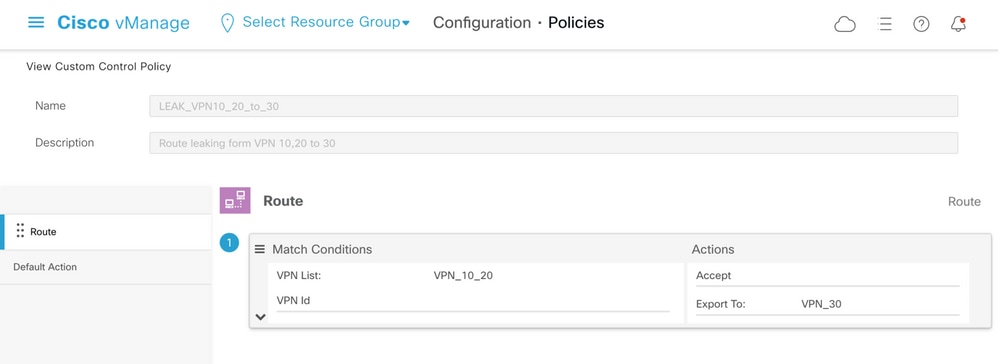
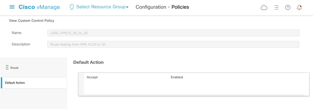
Note that the Default Action is set to Allow, to avoid the block of TLOC advertisements or normal intra-VPN routes advertisements accidentally.
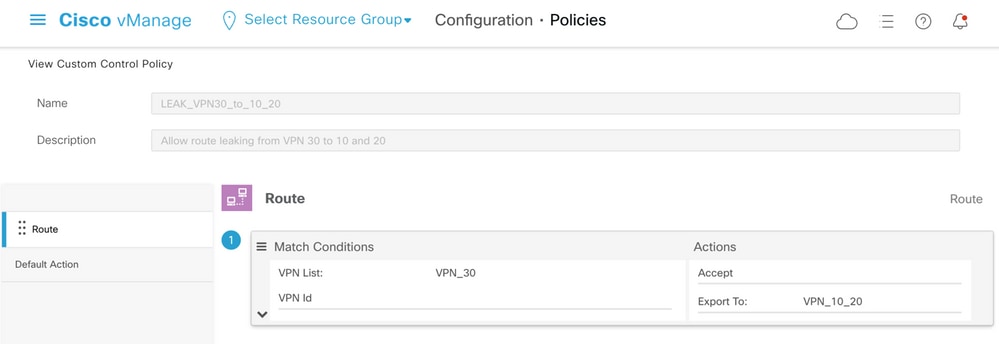
Similarly, the topology policy was configured to allow reverse advertisement of routing information from VPN 30 to VPN 10 and 20.

Then, both topology policies are assigned to the site lists that correspond, in the ingress (incoming) direction. Routes from VPN 30 are exported by the vSmart controller into Overlay Management Protocol (OMP) tables of VPN 10 and 20 when received from cE1 (site-id 11).
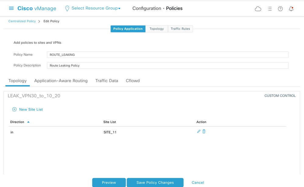
Similarly, routes from VPN 10 and 20 are exported by vSmart into the VPN 30 routing table on receipt of VPN 10 and 20 routes from cE2 (site-id 12).
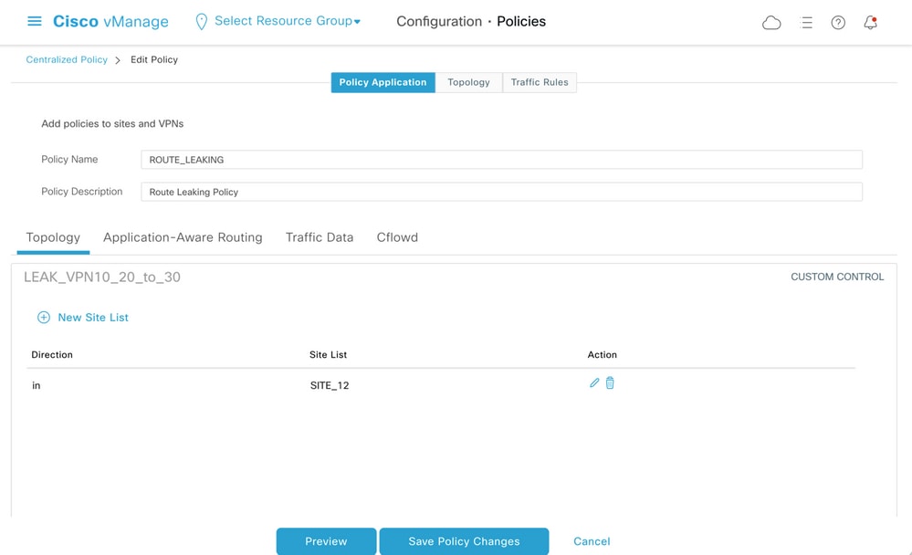
Here is also a complete control policy configuration preview for reference.
viptela-policy:policy
 control-policy LEAK_VPN10_20_to_30
    sequence 1
     match route
      vpn-list VPN_10_20
      prefix-list _AnyIpv4PrefixList
     !
     action accept
      export-to vpn-list VPN_30
     !
    !
  default-action accept
 !
 control-policy LEAK_VPN30_to_10_20
    sequence 1
     match route
      vpn-list VPN_30
      prefix-list _AnyIpv4PrefixList
     !
     action accept
      export-to vpn-list VPN_10_20
     !
    !
  default-action accept
 !
 lists
  site-list SITE_11
   site-id 11
  !
  site-list SITE_12
   site-id 12
  !
  vpn-list VPN_10_20
   vpn 10
   vpn 20
  !
  vpn-list VPN_30
   vpn 30
  !
  prefix-list _AnyIpv4PrefixList
   ip-prefix 0.0.0.0/0 le 32
  !
 !
!
apply-policy
 site-list SITE_12
  control-policy LEAK_VPN10_20_to_30 in
 !
 site-list SITE_11
  control-policy LEAK_VPN30_to_10_20 in
 !
!
The policy must be activated from the vManage controller Configuration > Policies section to be effective on the vSmart controller.
ZBFW Configuration
Here is a table that summarizes ZBFW to filter the requirements for the purpose of demonstration in this article.
|
Destination zone |
VPN_10 |
VPN_20 |
VPN_30 |
|
Source zone |
|||
|
VPN_10 |
intra-zone allow |
Deny |
Deny |
|
VPN_20 |
Deny |
intra-zone allow |
Allow |
|
VPN_30 |
Allow |
Deny |
intra-zone allow |
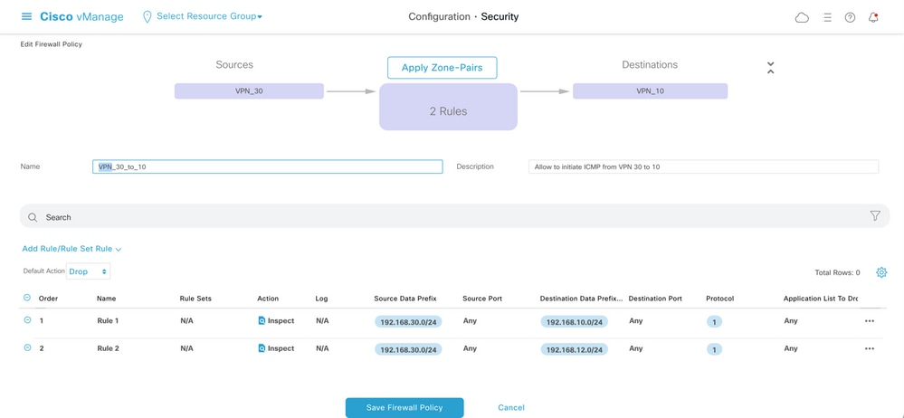
The main objective is to allow any Internet Control Message Protocol (ICMP) traffic that originated from the service-side of router cE1 VPN 30 and is destined to VPN 10 but not to VPN 20. Return traffic must be allowed automatically.
Also any ICMP traffic from the router cE2 service-side VPN 20 must be allowed to transit into VPN 30 service-side of cE1, but not from VPN 10. Return traffic from VPN 30 to VPN 20 must be allowed automatically.
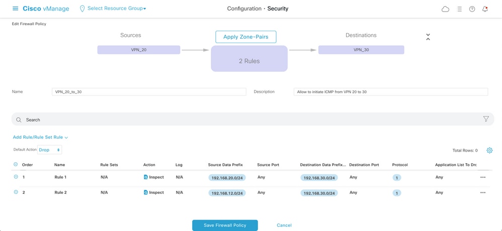
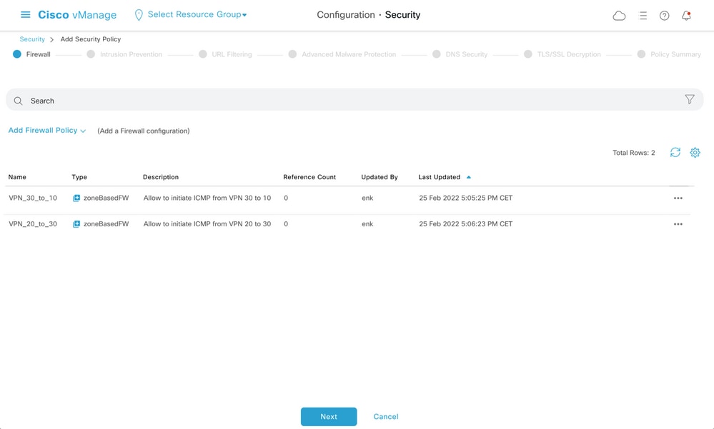
Here, you can find the ZBFW policy preview for reference.
policy
 zone-based-policy VPN_20_to_30
    sequence 1
     seq-name Rule_1
     match
      source-ip 192.168.20.0/24
      destination-ip 192.168.30.0/24
      protocol 1
     !
     action inspect
     !
    !
    sequence 11
     seq-name Rule_2
     match
      source-ip 192.168.12.0/24
      destination-ip 192.168.30.0/24
      protocol 1
     !
     action inspect
     !
    !
  default-action drop
 !
 zone-based-policy VPN_30_to_10
    sequence 1
     seq-name Rule_1
     match
      source-ip 192.168.30.0/24
      destination-ip 192.168.10.0/24
      protocol 1
     !
     action inspect
     !
    !
    sequence 11
     seq-name Rule_2
     match
      protocol 1
      source-ip 192.168.30.0/24
      destination-ip 192.168.12.0/24
     !
     action inspect
     !
    !
  default-action drop
 !
  zone VPN_10
   vpn 10
  !
  zone VPN_20
   vpn 20
  !
  zone VPN_30
   vpn 30
  !
  zone-pair ZP_VPN_20_VPN_30_VPN_20_to_30
   source-zone VPN_20
   destination-zone VPN_30
   zone-policy VPN_20_to_30
  !
  zone-pair ZP_VPN_30_VPN_10_VPN_30_to_10
   source-zone VPN_30
   destination-zone VPN_10
   zone-policy VPN_30_to_10
  !
 zone-to-nozone-internet deny
!
To apply security policy, it must be assigned under the Security Policy drop-down menu section of the Additional Templates section of the device template.
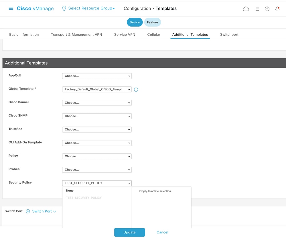
Once the device template is updated, the security policy becomes active on the device where the security policy was applied. For the purpose of demonstration in this document, it was enough to enable security policy on the cE1 router only.
Verify
Now you need to verify that the required security policy (ZBFW) objectives were achieved.
Test with ping confirms that the traffic from zone VPN 10 to VPN 30 is denied as expected because there is no zone-pair configured for traffic from VPN 10 to VPN 30.
R10#ping 192.168.30.30 source 192.168.10.10
Type escape sequence to abort.
Sending 5, 100-byte ICMP Echos to 192.168.30.30, timeout is 2 seconds:
Packet sent with a source address of 192.168.10.10
.....
Success rate is 0 percent (0/5)
R10#ping 192.168.30.30 source 192.168.12.12
Type escape sequence to abort.
Sending 5, 100-byte ICMP Echos to 192.168.30.30, timeout is 2 seconds:
Packet sent with a source address of 192.168.12.12
.....
Success rate is 0 percent (0/5)
Similarly, traffic from VPN 20 is allowed to VPN 30 as expected by the security policy configuration.
R20#ping 192.168.30.30 source 192.168.20.20
Type escape sequence to abort.
Sending 5, 100-byte ICMP Echos to 192.168.30.30, timeout is 2 seconds:
Packet sent with a source address of 192.168.20.20
!!!!!
Success rate is 100 percent (5/5), round-trip min/avg/max = 1/1/1 ms
R20#ping 192.168.30.30 source 192.168.12.12
Type escape sequence to abort.
Sending 5, 100-byte ICMP Echos to 192.168.30.30, timeout is 2 seconds:
Packet sent with a source address of 192.168.12.12
!!!!!
Success rate is 100 percent (5/5), round-trip min/avg/max = 1/1/1 ms
Traffic from VPN 30 to subnet 192.168.10.0/24 in zone VPN 10 is allowed as expected by policy configuration.
R30#ping 192.168.10.10 source 192.168.30.30
Type escape sequence to abort.
Sending 5, 100-byte ICMP Echos to 192.168.10.10, timeout is 2 seconds:
Packet sent with a source address of 192.168.30.30
!!!!!
Success rate is 100 percent (5/5), round-trip min/avg/max = 1/1/1 ms
Traffic from VPN 30 to subnet 192.168.20.0/24 in zone VPN 20 is denied because there is no zone pair configured for this traffic, which is expected.
R30#ping 192.168.20.20 source 192.168.30.30
Type escape sequence to abort.
Sending 5, 100-byte ICMP Echos to 192.168.20.20, timeout is 2 seconds:
Packet sent with a source address of 192.168.30.30
.....
Success rate is 0 percent (0/5)
Additional results that can interest you can be observed when you attempt to ping the IP address 192.168.12.12 because it can be in zone VPN 10 or VPN 20, and it is impossible to determine the destination VPN from the perspective of the router R30 situated on the service side of SD-WAN edge router cE1.
R30#ping 192.168.12.12 source 192.168.30.30
Type escape sequence to abort.
Sending 5, 100-byte ICMP Echos to 192.168.12.12, timeout is 2 seconds:
Packet sent with a source address of 192.168.30.30
.....
Success rate is 0 percent (0/5)
The result is the same for all sources in VRF 30. This confirms that it does not depend on Equal-Cost Multi-Path (ECMP) hash function results:
R30#ping 192.168.12.12 source 192.168.30.31
Type escape sequence to abort.
Sending 5, 100-byte ICMP Echos to 192.168.12.12, timeout is 2 seconds:
Packet sent with a source address of 192.168.30.31
.....
Success rate is 0 percent (0/5)
R30#ping 192.168.12.12 source 192.168.30.32
Type escape sequence to abort.
Sending 5, 100-byte ICMP Echos to 192.168.12.12, timeout is 2 seconds:
Packet sent with a source address of 192.168.30.32
.....
Success rate is 0 percent (0/5)
Based on test results for the destination IP 192.168.12.12, you can only guess that it locates in VPN 20 because it does not respond to the ICMP echo requests and is most likely blocked because there is no zone-pair configured to allow traffic from VPN 30 to VPN 20 (as desired). If a destination with the same IP address 192.168.12.12 would be located in VPN 10 and assumed to respond to ICMP echo request, then as per the ZBFW security policy for ICMP traffic from VPN 30 to VPN 20, traffic must be allowed. You must confirm the destination VPN.
Troubleshoot
Method 1. To Find Destination VPN from OMP Table
A simple check of the routing table on cE1 does not help to understand the actual destination VPN. The most useful information that you can get from the output is a system-IP of the destination (169.254.206.12) and also that there is no ECMP that happens.
cE1# show ip route vrf 30 192.168.12.0 255.255.255.0

Routing Table: 30
Routing entry for 192.168.12.0/24
  Known via "omp", distance 251, metric 0, type omp
  Last update from 169.254.206.12 on Sdwan-system-intf, 01:34:24 ago
  Routing Descriptor Blocks:
  * 169.254.206.12 (default), from 169.254.206.12, 01:34:24 ago, via Sdwan-system-intf
      Route metric is 0, traffic share count is 1
To find out the destination VPN, first, it is required to find out the service label from the OMP table on cE1 for the prefix of interest.
cE1#show sdwan omp routes vpn 30 192.168.12.0/24
Generating output, this might take time, please wait ...
Code:
C   -> chosen
I   -> installed
Red -> redistributed
Rej -> rejected
L   -> looped
R   -> resolved
S   -> stale
Ext -> extranet
Inv -> invalid
Stg -> staged
IA  -> On-demand inactive
U   -> TLOC unresolved
                 PATH                      ATTRIBUTE
FROM PEER        ID     LABEL    STATUS    TYPE       TLOC IP          COLOR            ENCAP  PREFERENCE
-----------------------------------------------------------------------------------------------------------
169.254.206.4    12     1007     C,I,R     installed  169.254.206.12   private2         ipsec  -
We can see that the label value is 1007. Finally, destination VPN can be found if all services that originate from the router which possesses system-IP 169.254.206.12 are checked on the vSmart controller.
vsmart1# show omp services family ipv4 service VPN originator 169.254.206.12
C   -> chosen
I   -> installed
Red -> redistributed
Rej -> rejected
L   -> looped
R   -> resolved
S   -> stale
Ext -> extranet
Inv -> invalid
Stg -> staged
IA  -> On-demand inactive
U   -> TLOC unresolved

                                                 PATH
VPN    SERVICE  ORIGINATOR      FROM PEER        ID     LABEL    STATUS
---------------------------------------------------------------------------
1      VPN      169.254.206.12  169.254.206.12   82     1003     C,I,R
2      VPN      169.254.206.12  169.254.206.12   82     1004     C,I,R
10     VPN      169.254.206.12  169.254.206.12   82     1006     C,I,R
17     VPN      169.254.206.12  169.254.206.12   82     1005     C,I,R
20     VPN      169.254.206.12  169.254.206.12   82     1007     C,I,R
Based on VPN label 1007 it can be confirmed that the destination VPN is 20.
Method 2. To Find Destination VPN with Help of Platform Commands
To find out the destination VPN with help of platform commands, first, you need to obtain an internal VRF ID for VPN 30 on the cE1 router with help of show ip vrf detail 30 or show platform software ip f0 cef table * summary commands.
cE1#show ip vrf detail 30 | i Id
VRF 30 (VRF Id = 1); default RD 1:30; default VPNID <not set>
cE1#show platform software ip f0 cef table * summary | i VRF|^30
Name             VRF id  Table id    Protocol         Prefixes    State
30               1       1           IPv4             21          hw: 0x561b60f07a50 (created)
In this case, VRF ID 1 was assigned to VRF named 30. Platform commands reveal the Output Chain Element (OCE) chain of objects in SD-WAN software that represent internal forwarding logic that determines packet path in Cisco IOS-XE software:
cE1#show platform software ip F0 cef table index 1 prefix 192.168.12.0/24 oce
=== Prefix OCE ===
Prefix/Len: 192.168.12.0/24
  Next Obj Type: OBJ_SDWAN_NH_SLA_CLASS
  Next Obj Handle: 0xf800045f, urpf: 0
  Prefix Flags: unknown
  aom id: 1717, HW handle: 0x561b60eeba20 (created)
The prefix of interest points to the next-hop object of Service Level Agreement (SLA) class type (OBJ_SDWAN_NH_SLA_CLASS) with ID 0xf800045f that can be further verified is shown here:
cE1#show platform software sdwan F0 next-hop sla id 0xf800045f
SDWAN Nexthop OCE

SLA: num_class 16, client_handle 0x561b610c3f10, ppe addr 0xdbce6c10
  SLA_0: num_nhops 1, Fallback_sla_flag TDL_FALSE, nhobj_type SDWAN_NH_INDIRECT
  ECMP: 0xf800044f 0xf800044f 0xf800044f 0xf800044f
        0xf800044f 0xf800044f 0xf800044f 0xf800044f
        0xf800044f 0xf800044f 0xf800044f 0xf800044f
        0xf800044f 0xf800044f 0xf800044f 0xf800044f
  SLA_1: num_nhops 0, Fallback_sla_flag TDL_FALSE, nhobj_type ADJ_DROP
  ECMP: 0xf800000f 0xf800000f 0xf800000f 0xf800000f
        0xf800000f 0xf800000f 0xf800000f 0xf800000f
        0xf800000f 0xf800000f 0xf800000f 0xf800000f
        0xf800000f 0xf800000f 0xf800000f 0xf800000f
<rest is omitted>
This is a long output, so SLA classes from 2 to 15 were skipped because there are no fallback SLA classes configured, and all of them point to the same special DROP adjacency as SLA 1. The main interest is the next-hop object of indirect type (SDWAN_NH_INDIRECT) from SLA 0. We can also note that there is no ECMP and all IDs are the same (0xf800044f). It can be further verified to find the ultimate destination VPN and service label.
cE1#show platform software sdwan F0 next-hop indirect id 0xf800044f
SDWAN Nexthop OCE

Indirect: client_handle 0x561b610f8140, ppe addr 0xd86b4cf0
  nhobj_type: SDWAN_NH_LOCAL_SLA_CLASS, nhobj_handle: 0xf808037f
  label: 1007, vpn: 20, sys-ip: 169.254.206.12, vrf_id: 1, sla_class: 1
Method 3. To Find Destination VPN with Help of Packet-Trace Tool
Another way to find a destination VPN is a packet-trace tool that can analyze real packets that run through the router in real-time. Debug condition is set to match traffic only to/from the IP address 192.168.12.12.
cE1#debug platform condition ipv4 192.168.12.12/32 both
cE1#debug platform packet-trace packet 10
 Please remember to turn on 'debug platform condition start' for packet-trace to work
cE1#debug platform condition start
Next, if traffic was initiated from R30 with help of ping, you can see matched packets on cE1 and check each packet detail. In this case, it is the very first packet number 0 for example. The most important lines are highlighted with <<<<< signs.
cE1#show platform packet-trace summary
Pkt   Input                     Output                    State  Reason
0     Gi6                       Tu3                       DROP   52  (FirewallL4Insp)
1     Gi6                       Tu3                       DROP   52  (FirewallL4Insp)
2     Gi6                       Tu3                       DROP   52  (FirewallL4Insp)
3     Gi6                       Tu3                       DROP   52  (FirewallL4Insp)
4     Gi6                       Tu3                       DROP   52  (FirewallL4Insp)
5     Gi6                       Tu3                       DROP   52  (FirewallL4Insp)


cE1#show platform packet-trace packet 0
Packet: 0           CBUG ID: 0
Summary
  Input     : GigabitEthernet6
  Output    : Tunnel3
  State     : DROP 52  (FirewallL4Insp) <<<<<<<<<<<<<<<<<<<<<<<<
  Timestamp
    Start   : 161062920614751 ns (03/24/2022 16:19:31.754050 UTC)
    Stop    : 161062920679374 ns (03/24/2022 16:19:31.754114 UTC)
Path Trace
  Feature: IPV4(Input)
    Input       : GigabitEthernet6
    Output      : <unknown>
    Source      : 192.168.30.30
    Destination : 192.168.12.12
    Protocol    : 1 (ICMP)
  Feature: SDWAN Forwarding
    SDWAN adj OCE:
    Output       : GigabitEthernet3
    Hash Value   : 0xda
    Encap        : ipsec
    SLA          : 0
    SDWAN VPN    : 20
    SDWAN Proto  : IPV4
    Out Label    : 1007 <<<<<<<<<<<<<<<<<<<<<<<<<<<<<<<<<<<<<<<
    Local Color  : private2
    Remote Color : private2
    FTM Tun ID   : 218
    SDWAN Session Info
      SRC IP       : 192.168.10.11
      SRC Port     : 12366
      DST IP       : 192.168.10.12
      DST Port     : 12346
      Remote System IP : 169.254.206.12
      Lookup Type : TUN_DEMUX
      Service Type : NONE
  Feature: ZBFW
    Action  : Drop
    Reason  : No Zone-pair found <<<<<<<<<<<<<<<<<<<<<<<<<<<<
    Zone-pair name         : N/A <<<<<<<<<<<<<<<<<<<<<<<<<<<<
    Class-map name         : N/A
    Policy    name         : N/A
    Input interface        : GigabitEthernet6
    Egress interface       : Tunnel3
    Input  VPN ID          : 30
    Output VPN ID          : 20 <<<<<<<<<<<<<<<<<<<<<<<<<<<<<
    Input  VRF ID:Name     : 1:30
    Output VRF ID:Name     : 1:30
    AVC Classification ID  : 0
    AVC Classification name: N/A
    UTD Context ID         : 0
A packet-trace tells that all five ICMP echo packets sent by ping were dropped with drop code 52 (FirewallL4Insp). Section Feature: SDWAN Forwarding tells that the destination VPN is 20 and service label 1007 in the internal header of the tunneled packet is used to forward to designate destination VPN on cE2. Section Feature: ZBFW further confirms that packets were dropped because the zone pair was not configured for traffic from Input VPN 20 destined to VPN 30 zone.
Potential Problems Due to Failover
What happens if route 192.168.12.0/24 is withdrawn by R20 or is not reachable anymore from cE2 in VRF 20? Though from a perspective of VRF 30 the subnet is the same, because ZBFW security policy treats traffic from zone VPN 30 to zones VPN 20 and 10 differently, it can lead to undesired results like traffic allowed, while it must not be or vice versa.
For example, if you simulate a failure of a link between cE2 and R20 routers. This leads to 192.168.12.0/24 route withdrawal from VPN 20 routing table on vSmart controller and instead, VPN 10 route is leaked into VPN 30 routing table. Connectivity from VPN 30 to VPN 10 is allowed as per the security policy applied on cE1 (this is expected from the perspective of security policy, but can not be desirable for the specific subnet presented in both VPNs).
cE1#show platform packet-trace packet 0
Packet: 0           CBUG ID: 644
Summary
  Input     : GigabitEthernet6
  Output    : GigabitEthernet3
  State     : FWD
  Timestamp
    Start   : 160658983624344 ns (03/24/2022 16:12:47.817059 UTC)
    Stop    : 160658983677282 ns (03/24/2022 16:12:47.817112 UTC)
Path Trace
  Feature: IPV4(Input)
    Input       : GigabitEthernet6
    Output      : <unknown>
    Source      : 192.168.30.30
    Destination : 192.168.12.12
    Protocol    : 1 (ICMP)
  Feature: SDWAN Forwarding
    SDWAN adj OCE:
    Output       : GigabitEthernet3
    Hash Value   : 0xda
    Encap        : ipsec
    SLA          : 0
    SDWAN VPN    : 10
    SDWAN Proto  : IPV4
    Out Label    : 1006
    Local Color  : private2
    Remote Color : private2
    FTM Tun ID   : 188
    SDWAN Session Info
      SRC IP       : 192.168.10.11
      SRC Port     : 12366
      DST IP       : 192.168.10.12
      DST Port     : 12346
      Remote System IP : 169.254.206.12
      Lookup Type : TUN_DEMUX
      Service Type : NONE
  Feature: ZBFW
    Action  : Fwd
    Zone-pair name         : ZP_VPN_30_VPN_10_VPN_30_to_10
    Class-map name         : VPN_30_to_10-seq-11-cm_
    Policy    name         : VPN_30_to_10
    Input interface        : GigabitEthernet6
    Egress interface       : Tunnel3
    Input  VPN ID          : 30
    Output VPN ID          : 10
    Input  VRF ID:Name     : 1:30
    Output VRF ID:Name     : 1:30
    AVC Classification ID  : 0
    AVC Classification name: N/A
    UTD Context ID         : 0
  Feature: IPSec
    Result    : IPSEC_RESULT_SA
    Action    : ENCRYPT
    SA Handle : 74
    Peer Addr : 192.168.10.12
    Local Addr: 192.168.10.11
Note that label 1006 was used instead of 1007 and Output VPN ID is 10 instead of 20 now. Also, the packet was allowed as per ZBFW security policy, and corresponding zone-pair, class-map, and policy names were given.
There is an even bigger problem that can arise due to the fact that the earliest route is kept in the routing table of VPN 30 and in this case it is the VPN 10 route that after the initial control policy application VPN 20 route was leaked into VPN 30 OMP table on vSmart. Imagine the scenario when the original idea was exactly the opposite of the ZBFW security policy logic described in this article. For example, the objective was to allow traffic from VPN 30 to VPN 20 and not to VPN 10. If it was allowed after an initial policy configuration, then after the failure or 192.168.12.0/24 route withdrawal from VPN 20, traffic remains blocked to the 192.168.12.0/24 subnet even after recovery because the 192.168.12.0/24 route still leaks from VPN 10.
Revision History
| Revision | Publish Date | Comments |
|---|---|---|
1.0 |
31-Mar-2022 |
Initial Release |
Contributed by Cisco Engineers
- Eugene KhabarovCisco Engineering
Contact Cisco
- Open a Support Case

- (Requires a Cisco Service Contract)
 Feedback