Introduction
This document describes how to implement Cisco SD-WAN DIA. It refers to the configuration when Internet traffic breaks out directly from branch router.
Prerequisites
Requirements
Cisco recommends that you have knowledge of these topics:
Components Used
The information in this document is based on these software and hardware versions:
- Cisco vManage version 20.6.3
- Cisco WAN Edge Router 17.4.2
The information in this document was created from the devices in a specific lab environment. All of the devices used in this document started with a cleared (default) configuration. If your network is live, ensure that you understand the potential impact of any command.
Network Diagram
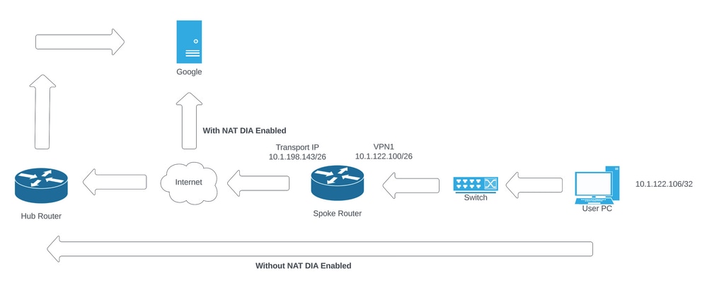 Network Topology
Configuration
DIA on Cisco SD-WAN routers is enabled in two steps:
1. Enable NAT on Transport Interface.
2. Direct traffic from service VPN with either a static route or a centralized data policy.
Enable NAT on Transport Interface
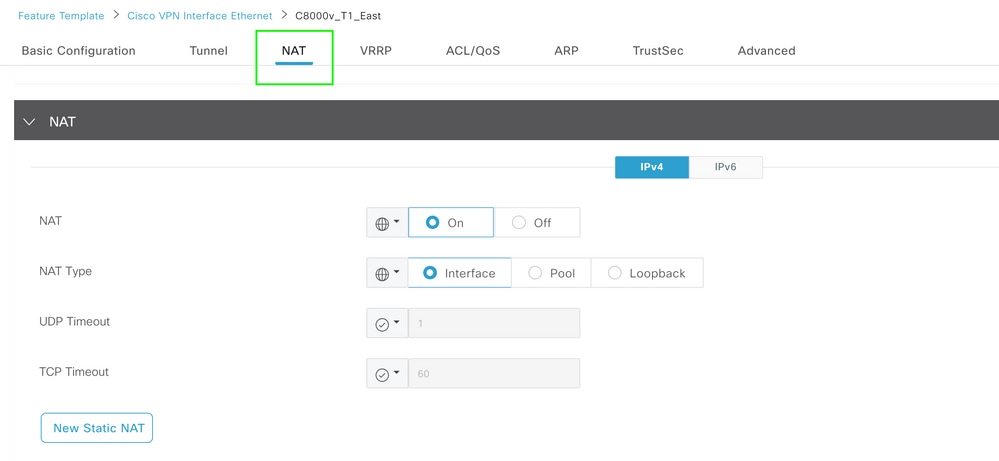 VPN Interface NAT Template
This is how the configuration looks post NAT is enabled.
ip nat inside source list nat-dia-vpn-hop-access-list interface GigabitEthernet2 overload
ip nat translation tcp-timeout 3600
ip nat translation udp-timeout 60

interface GigabitEthernet2
ip nat outside
Direct Traffic from Service VPN
This can be achieved in two ways:
1. Static NAT Route: A static NAT route needs to be created under the service VPN 1 feature template.
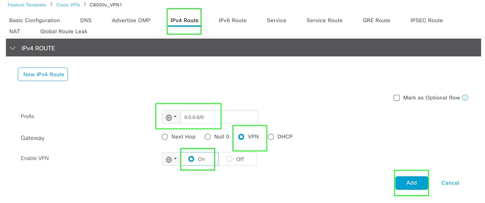 VPN 1 IPV4 Route Template
This line is pushed as part of the configuration.
ip nat route vrf 1 0.0.0.0 0.0.0.0 global
2. Centralized Data Policy:
Create a data prefix list, so specific users can be allowed to get Internet access via DIA.
 Centralized Policy Custom Data Prefix List
Create a VPN list, so specific VPN users can initiate traffic.
 Centralized Policy Custom VPN List
Create a site list, so that policy can be applied to a specific site.
 Centralized Policy Custom Site List
Create a custom Data policy in order to match the source data prefix and set the action to use NAT VPN 0, so it can traverse DIA.
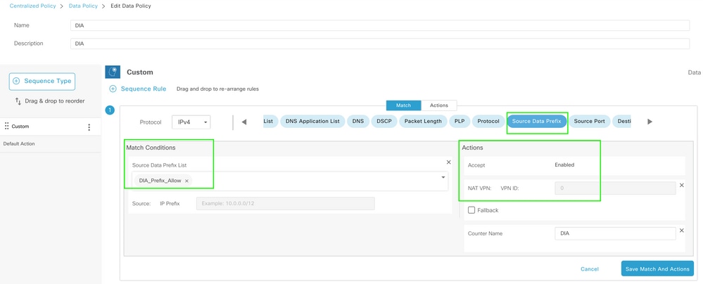 Centralized Data Policy
The direction of this policy must be from the service side.
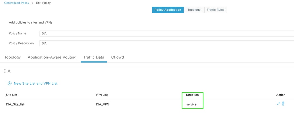 Traffic Data Rule
This is the preview for the centralized data policy.
viptela-policy:policy
 data-policy _DIA_VPN_DIA
  vpn-list DIA_VPN
    sequence 1
     match
      source-data-prefix-list DIA_Prefix_Allow
     !
     action accept
      nat use-vpn 0
      count DIA_1164863292
     !
    !
  default-action accept
 !
 lists
  data-prefix-list DIA_Prefix_Allow
   ip-prefix 10.1.122.106/32
  !
  site-list DIA_Site_list
   site-id 100004
  !
  vpn-list DIA_VPN
   vpn 1
  !
 !
!
apply-policy
 site-list DIA_Site_list
  data-policy _DIA_VPN_DIA from-service
 !
!
Verification
Without DIA
Next output captures when NAT DIA is not enabled on the service side.
cEdge_Site1_East_01#show ip route vrf 1 nat-route

Routing Table: 1
Codes: L - local, C - connected, S - static, R - RIP, M - mobile, B - BGP
       D - EIGRP, EX - EIGRP external, O - OSPF, IA - OSPF inter area
       N1 - OSPF NSSA external type 1, N2 - OSPF NSSA external type 2
       E1 - OSPF external type 1, E2 - OSPF external type 2, m - OMP
       n - NAT, Ni - NAT inside, No - NAT outside, Nd - NAT DIA
       i - IS-IS, su - IS-IS summary, L1 - IS-IS level-1, L2 - IS-IS level-2
       ia - IS-IS inter area, * - candidate default, U - per-user static route
       H - NHRP, G - NHRP registered, g - NHRP registration summary
       o - ODR, P - periodic downloaded static route, l - LISP
       a - application route
       + - replicated route, % - next hop override, p - overrides from PfR
       & - replicated local route overrides by connected

Gateway of last resort is not set

cEdge_Site1_East_01#
By default, users on VPN 1 do not have Internet access.
C:\Users\Administrator>ping 8.8.8.8

Pinging 8.8.8.8 with 32 bytes of data:
Reply from 10.1.122.100: Destination host unreachable.
Reply from 10.1.122.100: Destination host unreachable.
Reply from 10.1.122.100: Destination host unreachable.
Reply from 10.1.122.100: Destination host unreachable.

Ping statistics for 8.8.8.8:
Packets: Sent = 4, Received = 4, Lost = 0 (0% loss),

C:\Users\Administrator>
With DIA
1. Static NAT Route: Next output captures NAT DIA enabled on the service side.
cEdge_Site1_East_01#show ip route vrf 1 nat-route

Routing Table: 1
Codes: L - local, C - connected, S - static, R - RIP, M - mobile, B - BGP
       D - EIGRP, EX - EIGRP external, O - OSPF, IA - OSPF inter area
       N1 - OSPF NSSA external type 1, N2 - OSPF NSSA external type 2
       E1 - OSPF external type 1, E2 - OSPF external type 2, m - OMP
       n - NAT, Ni - NAT inside, No - NAT outside, Nd - NAT DIA
       i - IS-IS, su - IS-IS summary, L1 - IS-IS level-1, L2 - IS-IS level-2
       ia - IS-IS inter area, * - candidate default, U - per-user static route
       H - NHRP, G - NHRP registered, g - NHRP registration summary
       o - ODR, P - periodic downloaded static route, l - LISP
       a - application route
       + - replicated route, % - next hop override, p - overrides from PfR
       & - replicated local route overrides by connected

Gateway of last resort is 0.0.0.0 to network 0.0.0.0

n*Nd  0.0.0.0/0 [6/0], 01:41:46, Null0

cEdge_Site1_East_01#
Users in VPN 1 can now reach the Internet.
C:\Users\Administrator>ping 8.8.8.8

Pinging 8.8.8.8 with 32 bytes of data:
Reply from 8.8.8.8: bytes=32 time=1ms TTL=52
Reply from 8.8.8.8: bytes=32 time=1ms TTL=52
Reply from 8.8.8.8: bytes=32 time=1ms TTL=52
Reply from 8.8.8.8: bytes=32 time=1ms TTL=52

Ping statistics for 8.8.8.8:
Packets: Sent = 4, Received = 4, Lost = 0 (0% loss),
Approximate round trip times in milli-seconds:
Minimum = 1ms, Maximum = 1ms, Average = 1ms

C:\Users\Administrator>
The subsequent output captures NAT Translations.
cEdge_Site1_East_01#sh ip nat translations
Pro  Inside global         Inside local          Outside local         Outside global
icmp 10.1.198.143:1        10.1.122.106:1        8.8.8.8:1             8.8.8.8:1

Total number of translations: 1
The next command captures which path the packet must take.
cEdge_Site1_East_01#show sdwan policy service-path vpn 1 interface GigabitEthernet 4 source-ip 10.1.122.106 dest-ip 8.8.8.8 protocol 1
Next Hop: Remote
  Remote IP: 10.1.198.129, Interface GigabitEthernet2 Index: 8
2. Centralized Data Policy:
Once the Centralized Data policy is pushed to vSmart, the show sdwan policy from-vsmart data-policy command can be used on the WAN edge device in order to verify what policy the device has received.
cEdge_Site1_East_01#show sdwan policy from-vsmart data-policy
from-vsmart data-policy _DIA_VPN_DIA
 direction from-service
 vpn-list DIA_VPN
  sequence 1
   match
    source-data-prefix-list DIA_Prefix_Allow
   action accept
    count DIA_1164863292
    nat use-vpn 0
    no nat fallback
  default-action accept

cEdge_Site1_East_01#
Users in VPN 1 can now reach the Internet.
C:\Users\Administrator>ping 8.8.8.8

Pinging 8.8.8.8 with 32 bytes of data:
Reply from 8.8.8.8: bytes=32 time=4ms TTL=52
Reply from 8.8.8.8: bytes=32 time=1ms TTL=52
Reply from 8.8.8.8: bytes=32 time=1ms TTL=52
Reply from 8.8.8.8: bytes=32 time=1ms TTL=52

Ping statistics for 8.8.8.8:
Packets: Sent = 4, Received = 4, Lost = 0 (0% loss),
Approximate round trip times in milli-seconds:
Minimum = 1ms, Maximum = 4ms, Average = 1ms

C:\Users\Administrator>
The next command captures which path the packet must take.
cEdge_Site1_East_01#show sdwan policy service-path vpn 1 interface GigabitEthernet 4 source-ip 10.1.122.106 dest-ip 8.8.8.8 protocol 1
Next Hop: Remote
  Remote IP: 10.1.198.129, Interface GigabitEthernet2 Index: 8
The subsequent output captures NAT Translations.
cEdge_Site1_East_01#sh ip nat translations
Pro  Inside global         Inside local          Outside local         Outside global
icmp 10.1.198.143:1        10.1.122.106:1        8.8.8.8:1             8.8.8.8:1

Total number of translations: 1
This output captures the counter increments.
cEdge_Site1_East_01#show sdwan policy data-policy-filter
data-policy-filter _DIA_VPN_DIA
 data-policy-vpnlist DIA_VPN
  data-policy-counter DIA_1164863292
   packets 4
   bytes   296
  data-policy-counter default_action_count
   packets 0
   bytes   0

cEdge_Site1_East_01#
This output captures the traffic that is blackholed since the source IP does not belong to the data prefix list.
cEdge_Site1_East_01#show sdwan policy service-path vpn 1 interface GigabitEthernet 4 source-ip 10.1.122.107 dest-ip 8.8.8.8 protocol 1
Next Hop: Blackhole

cEdge_Site1_East_01#


 Feedback