Configure Policy-Based and Route-Based VPN from ASA and FTD to Microsoft Azure
Available Languages
Download Options
Bias-Free Language
The documentation set for this product strives to use bias-free language. For the purposes of this documentation set, bias-free is defined as language that does not imply discrimination based on age, disability, gender, racial identity, ethnic identity, sexual orientation, socioeconomic status, and intersectionality. Exceptions may be present in the documentation due to language that is hardcoded in the user interfaces of the product software, language used based on RFP documentation, or language that is used by a referenced third-party product. Learn more about how Cisco is using Inclusive Language.
Contents
Introduction
This document describes the concepts and configuration for a VPN between Cisco ASA and Cisco Secure Firewall and Microsoft Azure Cloud Services.
Prerequisites
Requirements
Cisco recommends that you have knowledge of these topics:
- For IKEv2 route-based VPN that uses VTI on ASA: ASA code version 9.8(1) or later. (Azure must be configured for route-based VPN.)
- For IKEv1 policy-based VPN that uses the crypto map on ASA and FTD: ASA code version 8.2 or later and FTD 6.2.0 or later. (Azure must be configured for policy-based VPN.)
- For IKEv2 route-based VPN that uses crypto map on ASA with policy-based traffic selectors: ASA code version 8.2 or later configured with a crypto map. (Azure must be configured for route-based VPN with UsePolicyBasedTrafficSelectors.)
- Knowledge of FMC for FTD management and configuration.
Components Used
The information in this document is based on these software and hardware versions:
- Cisco ASAv running ASA 9.18.4.22
- Microsoft Azure
- Cisco FTD
- Cisco FMC
The information in this document was created from the devices in a specific lab environment. All of the devices used in this document started with a cleared (default) configuration. If your network is live, ensure that you understand the potential impact of any command.
Background Information
Concepts
VPN Encryption Domain
The IP addresses range IPSec allows it to participate in the VPN tunnel.The encryption domain is defined with the use of a local traffic selector and remote traffic selector to specify what local and remote subnet ranges are captured and encrypted by IPSec.
Here are two methods to define the VPN encryption domains: route-based or policy-based traffic selectors.
Route-based:
The encryption domain is set to allow any traffic which enters the IPSec tunnel. IPSec Local and remote traffic selectors are set to 0.0.0.0. This means that any traffic routed into the IPSec tunnel is encrypted regardless of the source/destination subnet.
Cisco Adaptive Security Appliance (ASA) supports route-based VPN with the use of Virtual Tunnel Interfaces (VTIs) in versions 9.8 and later.
Cisco Secure Firewall or Firepower Threat Defense (FTD) managed by Firepower Management Center (FMC) supports route-based VPN with the use of VTIs in versions 6.7 and later.
Policy-based:
The encryption domain is set to encrypt only specific IP ranges for both source and destination. Policy-based local traffic selectors and remote traffic selectors identify what traffic to encrypt over IPSec.
ASA supports policy-based VPN with crypto maps in version 8.2 and later.
Microsoft Azure supports route-based, policy-based, or route-based with simulated policy-based traffic selectors. Azure currently restricts what Internet Key Exchange (IKE) version you are able to configure based upon the VPN selected method. Route-based requires IKEv2 and policy-based requires IKEv1. If IKEv2 is used, then route-based in Azure must be selected and ASA must use a VTI.
If the ASA only supports crypto maps due to code version, then Azure must be configured for route-based with policy-based traffic selectors.
This is accomplished in the Azure portal via PowerShell script deployment to implement an option that Microsoft calls UsePolicyBasedTrafficSelectors as explained here:
Connect a VPN Gateway to Multiple On-premises Policy-based VPN Devices
To summarize from the ASA and FTD configuration perspective:
- For ASA/FTD configured with a crypto map, Azure must be configured for policy-based VPN or route-based with UsePolicyBasedTrafficSelectors.
- For ASA configured with a VTI, Azure must be configured for route-based VPN.
- For FTD, further information on how to configure VTIs can be found here; Firepower Management Center Configuration Guide, Version 6.7
Configure
Complete the configuration steps. Choose to either configure IKEv1, IKEv2 Route Based with VTI, or IKEv2 Route Based with Use Policy-Based Traffic Selectors (crypto map on ASA).
IKEv1 Configuration on ASA
For a site-to-site IKEv1 VPN from ASA to Azure, implement the next ASA configuration. Ensure that you configure a policy-based tunnel in the Azure portal. Crypto maps are used on ASA for this example.
Reference Configure IKEv1 IPsec Site-to-Site Tunnels with the ASDM or CLI on the ASAv for full IKEv1 on ASA configuration information.
Step 1. Enable IKEv1 on the outside interface.
Cisco-ASA(config)#crypto ikev1 enable outside
Step 2. Create an IKEv1 policy that defines the algorithms/methods to be used for the hash, authentication, Diffie-Hellman group, lifetime, and encryption.
Note: The phase 1 IKEv1 attributes listed are provided best effort from About VPN Devices and IPsec/IKE Parameters for Site-to-Site VPN Gateway Connections. For further clarification, contact Microsoft Azure support.
Cisco-ASA(config)#crypto ikev1 policy 1
Cisco-ASA(config-ikev1-policy)#authentication pre-share
Cisco-ASA(config-ikev1-policy)#encryption aes
Cisco-ASA(config-ikev1-policy)#hash sha
Cisco-ASA(config-ikev1-policy)#group 14
Cisco-ASA(config-ikev1-policy)#lifetime 28800
Step 3. Create a tunnel group under the IPsec attributes and configure the peer IP address and the tunnel pre-shared key.
Cisco-ASA(config)#tunnel-group 192.168.1.1 type ipsec-l2l
Cisco-ASA(config)#tunnel-group 192.168.1.1 ipsec-attributes
Cisco-ASA(config-tunnel-ipsec)#ikev1 pre-shared-key cisco
Step 4. Create an access list that defines the traffic to be encrypted and tunneled.
In this example, the traffic of interest is from the tunnel that is sourced from the 10.2.2.0 subnet to 10.1.1.0. It can contain multiple entries if there are multiple subnets involved between the sites.
In Versions 8.4 and later, objects or object groups can be created that serve as containers for the networks, subnets, host IP addresses, or multiple objects.
Create two objects that have the local and remote subnets and use them for both the crypto Access Control List (ACL) and the Network Address Translation (NAT) statements.
Cisco-ASA(config)#object network 10.2.2.0_24
Cisco-ASA(config-network-object)#subnet 10.2.2.0 255.255.255.0
Cisco-ASA(config)#object network 10.1.1.0_24
Cisco-ASA(config-network-object)#subnet 10.1.1.0 255.255.255.0

Cisco-ASA(config)#access-list 100 extended permit ip object 10.2.2.0_24 object 10.1.1.0_24
Step 5. Configure the Transform Set (TS), which must involve the keywordIKEv1. An identical TS must be created on the remote end as well.
Note: The phase 2 IKEv1 attributes listed are provided best effort from About VPN Devices and IPsec/IKE Parameters for Site-to-Site VPN Gateway Connections. For further clarification, contact Microsoft Azure support.
Cisco-ASA(config)#crypto ipsec ikev1 transform-set myset esp-aes esp-sha-hmac
Step 6. Configure the crypto map and apply it to the outside interface, which has these components:
• The peer IP address
• The defined access list that contains the traffic of interest
• The TS
• The configuration does not set Perfect Forward Secrecy (PFS). About VPN Devices and IPsec/IKE Parameters for Site-to-Site VPN Gateway Connections states that PFS is disabled for IKEv1 in Azure.
An optional PFS setting creates a new pair of Diffie-Hellman keys that are used in order to protect the data (both sides must be PFS-enabled before Phase 2 comes up).
This setting can be enabled via the use of this configuration: crypto map outside_map 20 set pfs .
Cisco-ASA(config)#crypto map outside_map 20 match address 100
Cisco-ASA(config)#crypto map outside_map 20 set peer 192.168.1.1
Cisco-ASA(config)#crypto map outside_map 20 set ikev1 transform-set myset
Cisco-ASA(config)#crypto map outside_map 20 set security-association lifetime seconds 3600
Cisco-ASA(config)#crypto map outside_map 20 set security-association lifetime kilobytes 102400000
Cisco-ASA(config)#crypto map outside_map interface outside
Step 7. Ensure that the VPN traffic is not subjected to any other NAT rule. Create a NAT exemption rule:
Cisco-ASA(config)#nat (inside,outside) 1 source static 10.2.2.0_24 10.2.2.0_24 destination static 10.1.1.0_24 10.1.1.0_24 no-proxy-arp route-lookup
Note: When multiple subnets are used, you must create object groups with all of the source and destination subnets and use them in the NAT rule.
Cisco-ASA(config)#object-group network 10.x.x.x_SOURCE
Cisco-ASA(config-network-object-group)#network-object 10.4.4.0 255.255.255.0
Cisco-ASA(config-network-object-group)#network-object 10.2.2.0 255.255.255.0

Cisco-ASA(config)#object network 10.x.x.x_DESTINATION
Cisco-ASA(config-network-object-group)#network-object 10.3.3.0 255.255.255.0
Cisco-ASA(config-network-object-group)#network-object 10.1.1.0 255.255.255.0

Cisco-ASA(config)#nat (inside,outside) 1 source static 10.x.x.x_SOURCE 10.x.x.x_SOURCE destination static 10.x.x.x_DESTINATION 10.x.x.x_DESTINATION no-proxy-arp route-lookup
IKEv2 Route-based with VTI on ASA Code 9.8 (1) or Later
For a site-to-site IKEv2 Route Based VPN on ASA code, use this configuration. Ensure that Azure is configured for route-based VPN and do not configure UsePolicyBasedTrafficSelectors in the Azure portal. A VTI is configured on the ASA.
Reference CLI Book 3: Cisco ASA Series VPN CLI Configuration Guide, 9.8 for full ASA VTI configuration information.
Step 1. Enable IKEv2 on the outside interface:
Cisco-ASA(config)#crypto ikev2 enable outside
Step 2. Add an IKEv2 phase 1 policy.
Note: Microsoft has published information that conflicts with regards to the particular IKEv2 phase 1 encryption, integrity, and lifetime attributes used by Azure. The attributes listed are provided best effort from About VPN Devices and IPsec/IKE Parameters for Site-to-Site VPN Gateway Connections. The information that conflicts IKEv2 attribute from Microsoft is Sample Configuration: Cisco ASA Device (IKEv2/no BGP). For further clarification, contact Microsoft Azure support.
Cisco-ASA(config)#crypto ikev2 policy 1
Cisco-ASA(config-ikev2-policy)#encryption aes-256
Cisco-ASA(config-ikev2-policy)#integrity sha256
Cisco-ASA(config-ikev2-policy)#group 14
Cisco-ASA(config-ikev2-policy)#lifetime seconds 28800
Step 3. Add an IKEv2 phase 2 IPsec Proposal. Specify the security parameters in the crypto IPsec ikev2 ipsec-proposal configuration mode:
protocol esp encryption {des | 3des | aes | aes-192 | aes-256 | aes-gcm | aes-gcm-192 | aes-gcm-256 | aes-gmac | aes-gmac-192 | aes-gmac-256 | null}
protocol esp integrity {md5 | sha-1 | sha-256 | sha-384 | sha-512 | null}
Note: Microsoft has published information that conflicts with regards to the particular phase 2 IPSec encryption and integrity attributes used by Azure. The attributes listed are provided best effort from About VPN Devices and IPsec/IKE Parameters for Site-to-Site VPN Gateway Connections. The information that conflicts phase 2 IPSec attribute from Microsoft is Sample Configuration: Cisco ASA Device (IKEv2/no BGP). For further clarification, contact Microsoft Azure support.
Cisco-ASA(config)#crypto ipsec ikev2 ipsec-proposal SET1
Cisco-ASA(config-ipsec-proposal)#protocol esp encryption aes-256
Cisco-ASA(config-ipsec-proposal)#protocol esp integrity sha-256
Step 4. Add an IPSec profile that specifies:
- The previously configured ikev2 phase 2 IPSec proposal.
- The phase 2 IPSec lifetime (optional) in seconds and/or kilobytes.
- The PFS group (optional)
Note: Microsoft has published information that conflicts with regard to the particular phase 2 IPSec lifetime and PFS attributes used by Azure. The attributes listed are provided best effort from RouteBased VPN IPsec Security Association (IKE Quick Mode SA) Offers. The information that conflicts phase 2 IPSec attribute from Microsoft is Sample Configuration: Cisco ASA Device (IKEv2/no BGP). For further clarification, contact Microsoft Azure support.
Cisco-ASA(config)#crypto ipsec profile PROFILE1
Cisco-ASA(config-ipsec-profile)#set ikev2 ipsec-proposal SET1
Cisco-ASA(config-ipsec-profile)#set security-association lifetime seconds 27000
Cisco-ASA(config-ipsec-profile)#set security-association lifetime kilobytes unlimited
Cisco-ASA(config-ipsec-profile)#set pfs none
Step 5. Create a tunnel group under the IPsec attributes and configure the peer IP address and the IKEv2 local and remote tunnel pre-shared key:
Cisco-ASA(config)#tunnel-group 192.168.1.1 type ipsec-l2l
Cisco-ASA(config)#tunnel-group 192.168.1.1 ipsec-attributes
Cisco-ASA(config-tunnel-ipsec)#ikev2 local-authentication pre-shared-key cisco
Cisco-ASA(config-tunnel-ipsec)#ikev2 remote-authentication pre-shared-key cisco
Step 6. Create a VTI that specifies:
- A new tunnel interface number: interface tunnel [number]
- A new tunnel interface name: nameif [name]
- A non-existent IP address to exist on the tunnel interface: ip address [ip-address] [mask]
- Tunnel source interface where the VPN terminates locally: tunnel source interface [int-name]
- The Azure gateway IP address: tunnel destination [Azure Public IP]
- IPSec IPv4 mode: tunnel mode ipsec ipv4
- The IPSec profile to use for this VTI: tunnel protection ipsec profile [profile-name]
Cisco-ASA(config)#interface tunnel 100
Cisco-ASA(config-if)#nameif vti
Cisco-ASA(config-if)#ip address 169.254.0.1 255.255.255.252
Cisco-ASA(config-if)#tunnel source interface outside
Cisco-ASA(config-if)#tunnel destination [Azure Public IP]
Cisco-ASA(config-if)#tunnel mode ipsec ipv4
Cisco-ASA(config-if)#tunnel protection ipsec profile PROFILE1
Step 7. Create a static route to point traffic into the tunnel. To add a static route, enter this command: route if_name dest_ip mask gateway_ip [distance]
The dest_ip and mask is the IP address for the destination network in the Azure cloud, for instance, 10.0.0.0/24. The gateway_ip needs to be any IP address (existent or non-existent) on the tunnel interface subnet, such as 10.254.0.2. The purpose of this gateway_ip is to point traffic into the tunnel interface, but the particular gateway IP itself is not important.
Cisco-ASA(config)#route vti 10.0.0.0 255.255.255.0 10.254.0.2
IKEv1 Configuration on FTD
For a site-to-site IKEv1 VPN from FTD to Azure, you need to have previously registered the FTD device to FMC.
Step 1. Create a Site-to-Site policy. Navigate to the FMC dashboard > Devices > VPN > Site to Site.

Step 2. Create a new policy. Click the Add VPN dropdown menu and choose Firepower Threat Defense device.

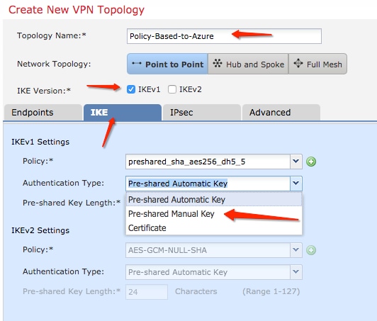
Step 3. On the Create new VPN Topology window, specify your Topology Name,check the IKEV1 protocol checkbox and click the IKE tab. For the purpose of this example, preshared keys are used as an authentication method.
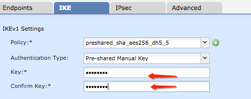
Click the Authentication Type dropdown menu, and choose Pre-shared manual key . Type the manual pre-shared key on the Key andConfirm Key text fields.
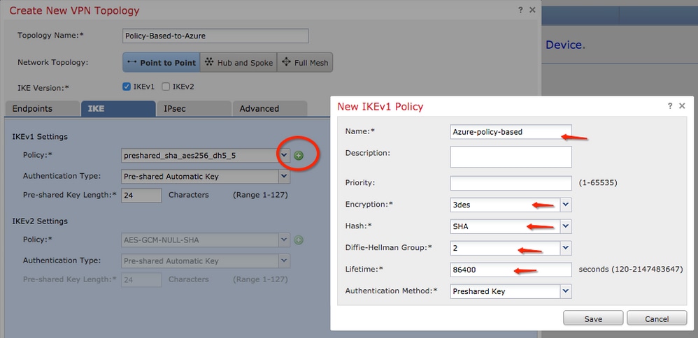
Step 4. Configure the ISAKMP policy or Phase 1 parameters with the creation of a new one. On the same window, click the green plus button to add a new ISAKMP policy. Specify the name of the policy and choose the desired Encryption, Hash, Diffie-Hellman Group, Lifetime, and Authentication Method, and click Save.
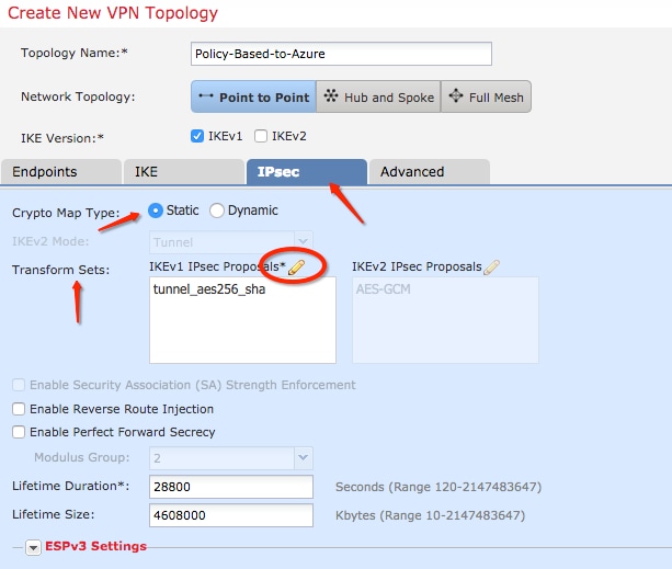
Step 5. Configure the IPsec policy or phase 2 parameters. Navigate to the IPsec tab, choose Static on the Crypto Map Type checkbox. Click the edit pencil icon from the IKEV1 IPsec Proposals at the Transform Sets option.
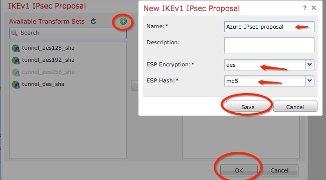
Step 6. Create a new IPsec proposal. On the IKEv1 IPSec Proposal window, click the green plus button to add a new one. Specify the name of the policy and its desired parameters for ESP Encryption and ESP Hash algorithms and click Save.
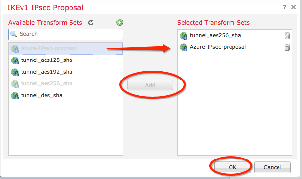
Step 7. On the IKEV1 IPsec Proposal window, add your new IPsec policy to the Selected Transform Sets section and click OK.
Step 8. Back on the IPSec tab, configure the desired Lifetime Duration and Size. 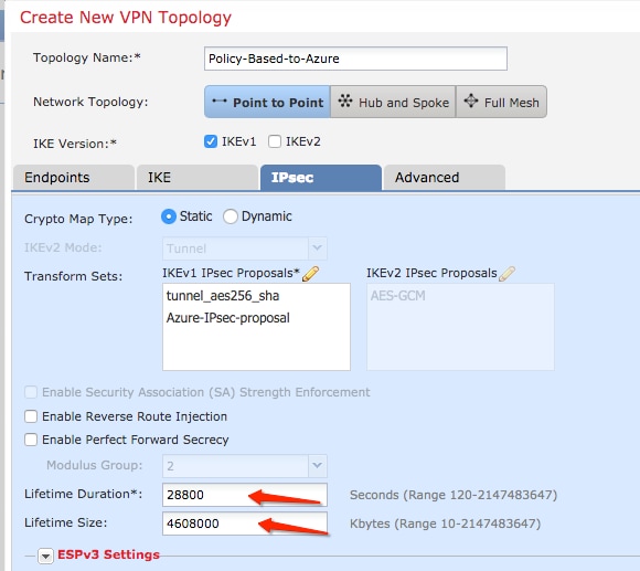
Step 9. Choose the Encryption Domain/Traffic Selectors/Protected Networks. Navigate to the Endpoints tab. On the Node A section click the green plus button to add a new one. In this example, Node A is used as the local subnets to the FTD.
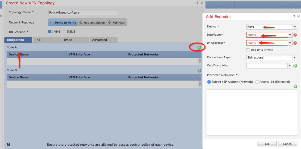
Step 10. On the Add Endpoint window, specify the FTD to use on the Device dropdown along with its physical interface and IP address to use.
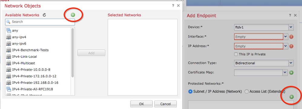
Step 11. To specify the local traffic selector, navigate to the Protected Networks option, and click the green plus button to create a new object.
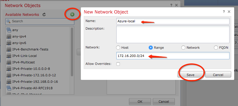
Step 12. On the Network Objects window, click the green plus button next to the Available Networks text to create a new local traffic selector object.
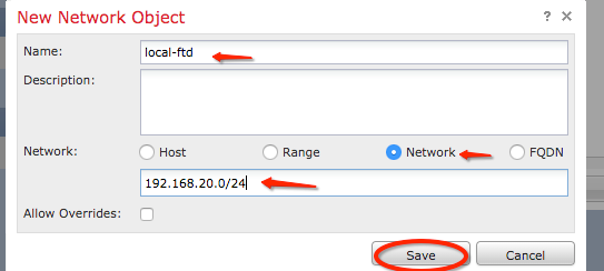
Step 13. On the New Network Object window, specify the name of the object and choose accordingly host/network/range/FQDN. Then, click Save .
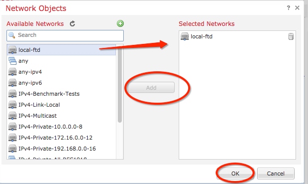
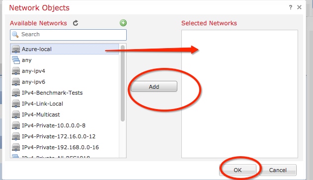
Step 14. Add the object to the Selected Networks section on the Network Objects window and click OK.Click OK on the Add Endpoint window.
Step 15. Define the Node B endpoint, which in this example, is the Azure endpoint. On the Create New VPN Topology window, navigate to the Node B section and click the green plus button to add the remote endpoint traffic selector. Specify Extranet for all VPN peer endpoints that are not managed by the same FMC as Node A. Type the name of the device (locally significant only) and its IP address.
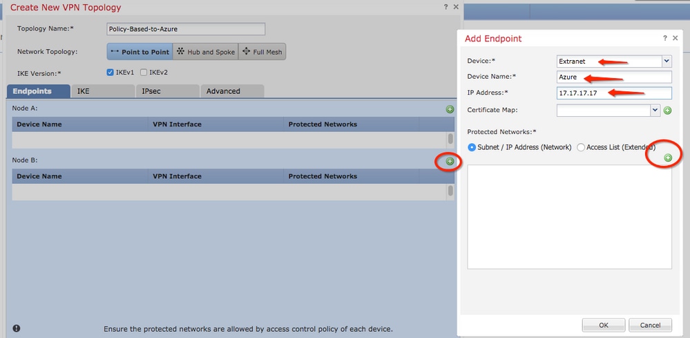
Step 16. Create the remote traffic selector object. Navigate to the Protected Networks section and click the green plus button to add a new object.
Step 17. On the Network Objects window, click the green plus button next to the Available Networks text to create a new object. On the New Network Object window, specify the name of the object and choose accordingly host/range/network/FQDN and click Save.
Step 18. Back on the Network Objects window, add your new remote object to the Selected Networks section and click OK. Click Ok on the Add Endpoint window.
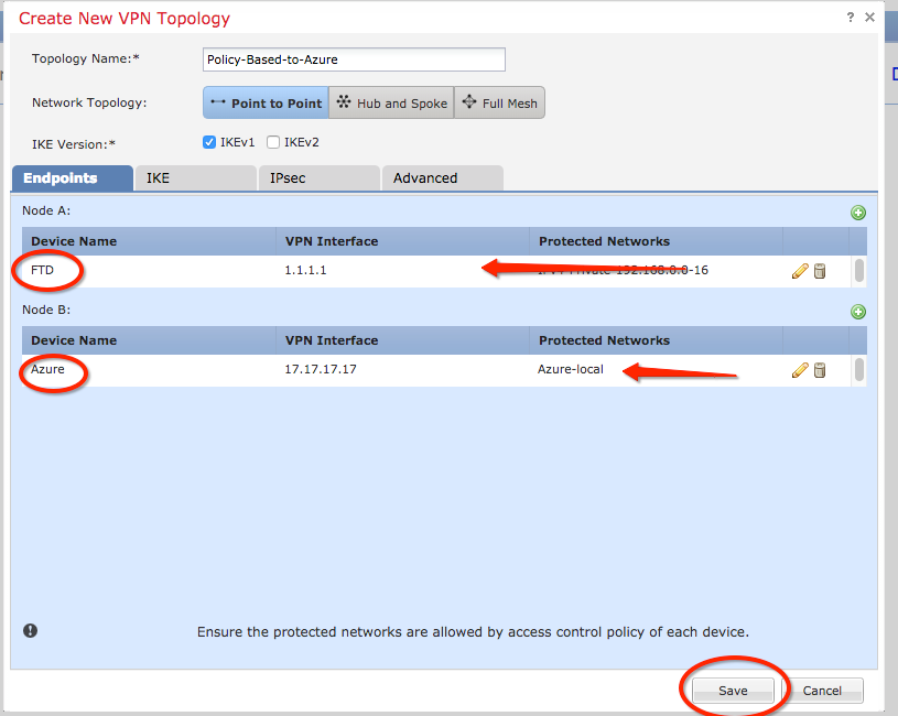
Step 19. On the Create New VPN Topology window, you can see now both nodes with their correct traffic selectors/protected networks. Click Save.
Step 20. On the FMC dashboard, click Deploy at the top-right pane, choose the FTD device, and click Deploy.
Step 21. On the command-line interface, the VPN configuration looks the same as the one for ASA devices.
IKEv2 Route-based with Policy-based Traffic Selectors
For a site-to-site IKEv2 VPN on ASA with crypto maps, use this configuration. Ensure that Azure is configured for route-based VPN and UsePolicyBasedTrafficSelectors must be configured in the Azure portal through the use of PowerShell.
Connect a VPN Gateway to Multiple On-premises Policy-based VPN Devices from Microsoft describes the configuration of UsePolicyBasedTrafficSelectors in conjunction with Route-Based Azure VPN mode. Without the completion of this step, ASA with crypto maps fails to establish the connection due to a mismatch in the traffic selectors received from Azure.
Reference CLI Book 3: Cisco ASA Series VPN CLI Configuration Guide, 9.8 for full ASA IKEv2 with crypto map configuration information.
Step 1. Enable IKEv2 on the outside interface:
Cisco-ASA(config)#crypto ikev2 enable outside
Step 2. Add an IKEv2 phase 1 policy.
Note: Microsoft has published information that conflicts with regards to the particular IKEv2 phase 1 encryption, integrity, and lifetime attributes used by Azure. The attributes listed are provided best effort from About VPN Devices and IPsec/IKE Parameters for Site-to-Site VPN Gateway Connections. IKEv2 attribute information from Microsoft that conflicts is Sample Configuration: Cisco ASA Device (IKEv2/no BGP). For further clarification contact Microsoft Azure support.
Cisco-ASA(config)#crypto ikev2 policy 1
Cisco-ASA(config-ikev2-policy)#encryption aes-256
Cisco-ASA(config-ikev2-policy)#integrity sha256
Cisco-ASA(config-ikev2-policy)#group 14
Cisco-ASA(config-ikev2-policy)#lifetime seconds 28800
Step 3. Create a tunnel group under the IPsec attributes and configure the peer IP address and the IKEv2 local and remote tunnel pre-shared key:
Cisco-ASA(config)#tunnel-group 192.168.1.1 type ipsec-l2l
Cisco-ASA(config)#tunnel-group 192.168.1.1 ipsec-attributes
Cisco-ASA(config-tunnel-ipsec)#ikev2 local-authentication pre-shared-key cisco
Cisco-ASA(config-tunnel-ipsec)#ikev2 remote-authentication pre-shared-key cisco
Step 4. Create an access list that defines the traffic to be encrypted and tunneled. In this example, the traffic of interest is the traffic from the tunnel that is sourced from the 10.2.2.0 subnet to 10.1.1.0. It can contain multiple entries if there are multiple subnets involved between the sites.
In Versions 8.4 and later, objects or object groups can be created that serve as containers for the networks, subnets, host IP addresses, or multiple objects. Create two objects that have the local and remote subnets and use them for both the crypto ACL and the NAT statements.
Cisco-ASA(config)#object network 10.2.2.0_24
Cisco-ASA(config-network-object)#subnet 10.2.2.0 255.255.255.0
Cisco-ASA(config)#object network 10.1.1.0_24
Cisco-ASA(config-network-object)#subnet 10.1.1.0 255.255.255.0

Cisco-ASA(config)#access-list 100 extended permit ip object 10.2.2.0_24 object 10.1.1.0_24
Step 5. Add an IKEv2 phase 2 IPsec Proposal. Specify the security parameters in the crypto IPsec ikev2 ipsec-proposal configuration mode:
protocol esp encryption {des | 3des | aes | aes-192 | aes-256 | aes-gcm | aes-gcm-192 | aes-gcm-256 | aes-gmac | aes-gmac-192 | aes-gmac-256 | null}
protocol esp integrity {md5 | sha-1 | sha-256 | sha-384 | sha-512 | null}
Note: Microsoft has published information that conflicts with regards to the particular phase 2 IPSec encryption and integrity attributes used by Azure. The attributes listed are provided best effort from RouteBased VPN IPsec Security Association (IKE Quick Mode SA) Offers. Phase 2 IPSec attribute information from Microsoft that conflicts is Sample Configuration: Cisco ASA Device (IKEv2/no BGP). For further clarification contact Microsoft Azure support.
Cisco-ASA(config)#crypto ipsec ikev2 ipsec-proposal SET1
Cisco-ASA(config-ipsec-proposal)#protocol esp encryption aes-256
Cisco-ASA(config-ipsec-proposal)#protocol esp integrity sha-256
Step 6. Configure a crypto map and apply it to the outside interface, which contains these components:
• The peer IP address
• The defined access list that contains the traffic of interest.
• The IKEv2 phase 2 IPSec Proposal
• The phase 2 IPSec lifetime in seconds.
• An optional Perfect Forward Secrecy (PFS) setting, which creates a new pair of Diffie-Hellman keys that are used in order to protect the data (both sides must be PFS-enabled before Phase 2 comes up).
Microsoft has published information that conflicts with regard to the particular phase 2 IPSec lifetime and PFS attributes used by Azure.
The attributes listed are provided best effort from RouteBased VPN IPsec Security Association (IKE Quick Mode SA) Offers.
Phase 2 IPSec attribute information from Microsoft that conflicts is Sample Configuration: Cisco ASA Device (IKEv2/no BGP). For further clarification, contact Microsoft Azure support.
Cisco-ASA(config)#crypto map outside_map 20 match address 100
Cisco-ASA(config)#crypto map outside_map 20 set peer 192.168.1.1
Cisco-ASA(config)#crypto map outside_map 20 set ikev2 ipsec-proposal myset
Cisco-ASA(config)#crypto map outside_map 20 set security-association lifetime seconds 27000
Cisco-ASA(config)#crypto map outside_map 20 set security-association lifetime kilobytes unlimited
Cisco-ASA(config)#crypto map outside_map 20 set pfs none
Cisco-ASA(config)#crypto map outside_map interface outside
Step 8. Ensure that the VPN traffic is not subjected to any other NAT rule. Create a NAT exemption rule:
Cisco-ASA(config)#nat (inside,outside) 1 source static 10.2.2.0_24 10.2.2.0_24 destination static 10.1.1.0_24 10.1.1.0_24 no-proxy-arp route-lookup
Note: When multiple subnets are used, you must create object groups with all of the source and destination subnets and use them in the NAT rule.
Cisco-ASA(config)#object-group  network 10.x.x.x_SOURCE
Cisco-ASA(config-network-object-group)#network-object  10.4.4.0 255.255.255.0
Cisco-ASA(config-network-object-group)#network-object  10.2.2.0 255.255.255.0

Cisco-ASA(config)#object network 10.x.x.x_DESTINATION
Cisco-ASA(config-network-object-group)#network-object  10.3.3.0 255.255.255.0
Cisco-ASA(config-network-object-group)#network-object  10.1.1.0 255.255.255.0

Cisco-ASA(config)#nat (inside,outside) 1 source static 10.x.x.x_SOURCE 10.x.x.x_SOURCE destination static 10.x.x.x_DESTINATION  10.x.x.x_DESTINATION no-proxy-arp route-lookup
Verify
After you complete the configuration on both ASA and the Azure gateway, Azure initiates the VPN tunnel. You can verify that the tunnel builds correctly with these commands:
Phase 1
Verify the phase 1 Security Association (SA) has been built:
Next, an IKEv2 SA built from local outside interface IP 192.168.1.2 on UDP port 500, to the remote destination IP 192.168.2.2 is shown. There is also a valid child SA built for encrypted traffic to flow over.
Cisco-ASA# show crypto ikev2 sa

IKEv2 SAs:

Session-id:44615, Status:UP-ACTIVE, IKE count:1, CHILD count:1

Tunnel-id Local                                               Remote                                                  Status         Role
  3208253 192.168.1.2/500                                     192.168.2.2/500                                          READY    INITIATOR
      Encr: AES-CBC, keysize: 256, Hash: SHA256, DH Grp:14, Auth sign: PSK, Auth verify: PSK
      Life/Active Time: 86400/142 sec
*-->Child sa: local selector  192.168.0.0/0 - 192.168.0.255/65535
          remote selector 192.168.3.0/0 - 192.168.3.255/65535
          ESP spi in/out: 0x9b60edc5/0x8e7a2e12
Here, an IKEv1 SA built with ASA as the initiator to peer IP 192.168.2.2 with a leftover lifetime of 86388 seconds is shown.
Cisco-ASA# sh crypto ikev1 sa detail

IKEv1 SAs:

   Active SA: 1
    Rekey SA: 0 (A tunnel will report 1 Active and 1 Rekey SA during rekey)
Total IKE SA: 1

1   IKE Peer: 192.168.2.2
    Type    : L2L             Role    : initiator
    Rekey   : no              State   : MM_ACTIVE
    Encrypt : aes             Hash    : SHA
    Auth    : preshared       Lifetime: 86400
    Lifetime Remaining: 86388
Phase 2
Verify the phase 2 IPSec security association has built with show crypto ipsec sa peer [peer-ip].
Cisco-ASA# show crypto ipsec sa peer 192.168.2.2
peer address: 192.168.2.2
 Crypto map tag: outside, seq num: 10, local addr: 192.168.1.2

 access-list VPN extended permit ip 192.168.0.0 255.255.255.0 192.168.3.0 255.255.255.0
 local ident (addr/mask/prot/port): (192.168.0.0/255.255.255.0/0/0)
 remote ident (addr/mask/prot/port): (192.168.3.0/255.255.255.0/0/0)
 current_peer: 192.168.2.2


 #pkts encaps: 4, #pkts encrypt: 4, #pkts digest: 4
 #pkts decaps: 4, #pkts decrypt: 4, #pkts verify: 4
 #pkts compressed: 0, #pkts decompressed: 0
 #pkts not compressed: 4, #pkts comp failed: 0, #pkts decomp failed: 0
 #pre-frag successes: 0, #pre-frag failures: 0, #fragments created: 0
 #PMTUs sent: 0, #PMTUs rcvd: 0, #decapsulated frgs needing reassembly: 0
 #TFC rcvd: 0, #TFC sent: 0
 #Valid ICMP Errors rcvd: 0, #Invalid ICMP Errors rcvd: 0
 #send errors: 0, #recv errors: 0

 local crypto endpt.: 192.168.1.2/500, remote crypto endpt.: 192.168.2.2/500
 path mtu 1500, ipsec overhead 74(44), media mtu 1500
 PMTU time remaining (sec): 0, DF policy: copy-df
 ICMP error validation: disabled, TFC packets: disabled
 current outbound spi: 8E7A2E12
 current inbound spi : 9B60EDC5

 inbound esp sas:
 spi: 0x9B60EDC5 (2606820805)
 SA State: active
 transform: esp-aes-256 esp-sha256-hmac no compression
 in use settings ={L2L, Tunnel, IKEv2, }
 slot: 0, conn_id: 182743040, crypto-map: outside
 sa timing: remaining key lifetime (kB/sec): (4193279/28522)
 IV size: 16 bytes
 replay detection support: Y
 Anti replay bitmap:
 0x00000000 0x0000001F

 outbound esp sas:
 spi: 0x8E7A2E12 (2390371858)
 SA State: active
 transform: esp-aes-256 esp-sha256-hmac no compression
 in use settings ={L2L, Tunnel, IKEv2, }
 slot: 0, conn_id: 182743040, crypto-map: outside
 sa timing: remaining key lifetime (kB/sec): (3962879/28522)
 IV size: 16 bytes
 replay detection support: Y
 Anti replay bitmap:
 0x00000000 0x00000001
Four packets are sent and four are received over the IPSec SA with no errors. One inbound SA with SPI 0x9B60EDC5 and one outbound SA with SPI 0x8E7A2E12 are installed as expected.
You can also verify that data passes over the tunnel through a check of the vpn-sessiondb l2l entries:
Cisco-ASA#show vpn-sessiondb l2l

Session Type: LAN-to-LAN

Connection : 192.168.2.2
Index : 44615 IP Addr : 192.168.2.2
Protocol : IKEv2 IPsec
Encryption : IKEv2: (1)AES256 IPsec: (1)AES256
Hashing : IKEv2: (1)SHA256 IPsec: (1)SHA256
Bytes Tx : 400 Bytes Rx : 400
Login Time : 18:32:54 UTC Tue Mar 13 2018
Duration : 0h:05m:22s
Bytes Tx: and Bytes Rx: show sent and received data counters over the IPSec SA.
Troubleshoot
Step 1. Verify that traffic for the VPN is received by ASA on the inside interface destined for the Azure private network. To test, you can configure a continuous ping from an inside client and configure a packet capture on ASA to verify it is received:
capture [cap-name] interface [if-name] match [protocol] [src-ip] [src-mask] [dest-ip] [dest-mask]
show capture [cap-name]
Cisco-ASA#capture inside interface inside match ip host [local-host] host [remote-host]
Cisco-ASA#show capture inside

2 packets captured

   1: 18:50:42.835863       192.168.0.2 > 192.168.3.2: icmp: echo request
   2: 18:50:42.839128       192.168.3.2 > 192.168.0.2: icmp: echo reply
2 packets shown
If reply traffic from Azure is seen, then the VPN is properly built and sends/receives traffic.
If source traffic is absent, verify that your sender is properly routing to the ASA.
If source traffic is seen, but reply traffic from Azure is absent, continue on to verify why.
Step 2. Verify that the traffic received on ASA inside interface is properly processed by ASA and routed into the VPN:
To simulate an ICMP echo request:
packet-tracer input [inside-interface-name] icmp [inside-host-ip] 8 0 [azure-host-ip] detail
Full packet-tracer usage guidelines can be found here: Troubleshooting Access Problems Using Packet-Tracer
Cisco-ASA# packet-tracer input inside icmp 192.168.0.2 8 0 192.168.3.2 detail

Phase: 1
Type: CAPTURE
Subtype:
Result: ALLOW
Config:
Additional Information:
 Forward Flow based lookup yields rule:
 in  id=0x7f6c19afb0a0, priority=13, domain=capture, deny=false
        hits=3, user_data=0x7f6c19afb9b0, cs_id=0x0, l3_type=0x0
        src mac=0000.0000.0000, mask=0000.0000.0000
        dst mac=0000.0000.0000, mask=0000.0000.0000
        input_ifc=inside, output_ifc=any

Phase: 2
Type: ACCESS-LIST
Subtype:
Result: ALLOW
Config:
Implicit Rule
Additional Information:
 Forward Flow based lookup yields rule:
 in  id=0x7f6c195971f0, priority=1, domain=permit, deny=false
        hits=32, user_data=0x0, cs_id=0x0, l3_type=0x8
        src mac=0000.0000.0000, mask=0000.0000.0000
        dst mac=0000.0000.0000, mask=0100.0000.0000
        input_ifc=inside, output_ifc=any

Phase: 3
Type: ROUTE-LOOKUP
Subtype: Resolve Egress Interface
Result: ALLOW
Config:
Additional Information:
found next-hop 192.168.1.1 using egress ifc  outside

Phase: 4
Type: NAT
Subtype: per-session
Result: ALLOW
Config:
Additional Information:
 Forward Flow based lookup yields rule:
 in  id=0x7f6c19250290, priority=0, domain=nat-per-session, deny=true
        hits=41, user_data=0x0, cs_id=0x0, reverse, use_real_addr, flags=0x0, protocol=0
        src ip/id=0.0.0.0, mask=0.0.0.0, port=0, tag=any
        dst ip/id=0.0.0.0, mask=0.0.0.0, port=0, tag=any, dscp=0x0
        input_ifc=any, output_ifc=any

Phase: 5
Type: IP-OPTIONS
Subtype:
Result: ALLOW
Config:
Additional Information:
 Forward Flow based lookup yields rule:
 in  id=0x7f6c1987c120, priority=0, domain=inspect-ip-options, deny=true
        hits=26, user_data=0x0, cs_id=0x0, reverse, flags=0x0, protocol=0
        src ip/id=0.0.0.0, mask=0.0.0.0, port=0, tag=any
        dst ip/id=0.0.0.0, mask=0.0.0.0, port=0, tag=any, dscp=0x0
        input_ifc=inside, output_ifc=any

Phase: 6
Type: QOS
Subtype:
Result: ALLOW
Config:
Additional Information:
 Forward Flow based lookup yields rule:
 in  id=0x7f6c19a60280, priority=70, domain=qos-per-class, deny=false
        hits=30, user_data=0x7f6c19a5c030, cs_id=0x0, reverse, use_real_addr, flags=0x0, protocol=0
        src ip/id=0.0.0.0, mask=0.0.0.0, port=0, tag=any
        dst ip/id=0.0.0.0, mask=0.0.0.0, port=0, tag=any, dscp=0x0
        input_ifc=any, output_ifc=any

Phase: 7
Type: INSPECT
Subtype: np-inspect
Result: ALLOW
Config:
Additional Information:
 Forward Flow based lookup yields rule:
 in  id=0x7f6c1983ab50, priority=66, domain=inspect-icmp-error, deny=false
        hits=27, user_data=0x7f6c1987afc0, cs_id=0x0, use_real_addr, flags=0x0, protocol=1
        src ip/id=0.0.0.0, mask=0.0.0.0, icmp-type=0, tag=any
        dst ip/id=0.0.0.0, mask=0.0.0.0, icmp-code=0, tag=any, dscp=0x0
        input_ifc=inside, output_ifc=any

Phase: 8
Type: VPN
Subtype: encrypt
Result: ALLOW
Config:
Additional Information:
 Forward Flow based lookup yields rule:
 out id=0x7f6c19afe1a0, priority=70, domain=encrypt, deny=false
        hits=2, user_data=0x13134, cs_id=0x7f6c19349670, reverse, flags=0x0, protocol=0
        src ip/id=192.168.0.0, mask=255.255.255.0, port=0, tag=any
        dst ip/id=192.168.3.0, mask=255.255.255.0, port=0, tag=any, dscp=0x0
        input_ifc=any, output_ifc=outside

Phase: 9
Type: FLOW-CREATION
Subtype:
Result: ALLOW
Config:
Additional Information:
New flow created with id 43, packet dispatched to next module
Module information for forward flow ...
snp_fp_tracer_drop
snp_fp_inspect_ip_options
snp_fp_inspect_icmp
snp_fp_adjacency
snp_fp_encrypt
snp_fp_fragment
snp_ifc_stat

Module information for reverse flow ...

Result:
input-interface: inside
input-status: up
input-line-status: up
output-interface: outside
output-status: up
output-line-status: up
Action: allow
NAT exempts traffic (no translation takes effect). Verify no NAT translation occurs on the VPN traffic. Also, verify the output-interface is correct - it must be either the physical interface where the crypto map is applied or the virtual tunnel interface.
Ensure that there are no access-list drops seen. If the VPN phase shows ENCRYPT: ALLOW, the tunnel is already built and you can see IPSec SA installed with encaps.
Step 2.1. If ENCRYPT: ALLOW is seen in packet-tracer.
Verify IPsec SA is installed and encrypts traffic with the use of show crypto ipsec sa.
You can perform a capture on the outside interface to verify that encrypted packets are sent from ASA and encrypted responses are received from Azure.
Step 2.2. If ENCRYPT:DROP seen in packet-tracer.
VPN tunnel is not yet established but is in negotiation. This is an expected condition when you first bring the tunnel up. Run debugs to view the tunnel negotiation process and identify where and if a failure occurs.
First, verify the correct version of IKE is triggered and that the ike-common process shows no relevant errors:
Cisco-ASA#debug crypto ike-common 255

Cisco-ASA# Mar 13 18:58:14 [IKE COMMON DEBUG]Tunnel Manager dispatching a KEY_ACQUIRE message to IKEv1.  Map Tag = outside.  Map Sequence Number = 10.
If no ike-common debug output is seen when VPN traffic is initiated, this means traffic is dropped before it reaches the crypto process or crypto ikev1/ikev2 is not enabled on the box. Double-check the crypto configuration and packet drops.
If ike-common debugs show the crypto process is triggered, debug the IKE configured version to view tunnel negotiation messages and identify where the failure occurs in tunnel-building with Azure.
IKEv1
Full ikev1 debug procedure and analysis can be found here ASA IPsec and IKE Debugs (IKEv1 Main Mode) Troubleshooting TechNote.
Cisco-ASA#debug crypto ikev1 127
Cisco-ASA#debug crypto ipsec 127
IKEv2
Full ikev2 debug procedure and analysis can be found here Use ASA IKEv2 Debugs for Site-to-Site VPN with PSKs
Cisco-ASA#debug crypto ikev2 platform 127
Cisco-ASA#debug crypto ikev2 protocol 127
Cisco-ASA#debug crypto ipsec 127
Revision History
| Revision | Publish Date | Comments |
|---|---|---|
4.0 |
07-Oct-2024 |
Updated Article Description, Image Links, Style Requirements, and Formatting. |
3.0 |
09-Sep-2022 |
Content Review/Recertification |
2.0 |
28-Feb-2022 |
Support for FTD 6.7 has been added as part of firestarter request. |
1.0 |
27-Mar-2019 |
Initial Release |
Contributed by Cisco Engineers
- Shawn WinnerTechnical Consulting Engineer
- Alan Garcia MarchanTechnical Consulting Engineer
- Cesar Lopez ZamarripaTechnical Consulting Engineer
Contact Cisco
- Open a Support Case

- (Requires a Cisco Service Contract)
 Feedback