Introduction
This document describes how to troubleshoot a RADIUS server marked as failed in ASA and how this can cause outages for the client infrastructure.
Prerequisites
Requirements
Cisco recommends that you have knowledge of these topics:
- Basic awareness or EEM scripting on Cisco ASA
Components Used
This document is not restricted to specific software and hardware versions.
The information in this document was created from the devices in a specific lab environment. All of the devices used in this document started with a cleared (default) configuration. If your network is live, ensure that you understand the potential impact of any command.
Problem
RADIUS servers are marked as failed/dead in the Cisco ASA. The problem is intermittent but causes outages for the client infrastructure. TAC must differentiate whether this is an ASA issue, Data Path issue, or Radius Server issue. If a capture is made at the time of failure, it rules out the Cisco ASA as it discerns whether the ASA sends the packets to the RADIUS server, and if they are received in return.
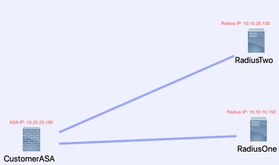
Topology
For this example, this is the topology that is used:

To fix this problem, do these next steps.
Step 1: Configure Packet Capture and Applicable Access-Lists to capture Packets between Servers
The first step is to configure Packet Capture and applicable access-lists to capture packets between the ASA and RADIUS servers.
If you need assistance with Packet Capture, refer to the Packet Capture Config Generator and Analyzer.
access-list TAC extended permit ip host 10.20.20.180 host 10.10.10.150
access-list TAC extended permit ip host 10.10.10.150 host 10.20.20.180
access-list TAC extended permit ip host 10.20.20.180 host 10.10.20.150
access-list TAC extended permit ip host 10.10.20.150host 10.20.20.180
capture RADIUS type raw-data access-list TAC buffer 30000000 interface inside circular-buffer
Note: You need to check the buffer size to ensure that it does not overfill and does the data. A buffer size of 1000000 is sufficient. Notice our example buffer is 3000000.
Step 2: Configure EEM Script
Next, configure the EEM script.
This example uses the Syslog ID of 113022 and you can trigger EEM on many other Syslog messages:
The message types for ASA are found at Cisco Secure Firewall ASA Series Syslog Messages.
The trigger in this scenario is:
Error Message %ASA-113022: AAA Marking RADIUS server servername in aaa-server group AAA-Using-DNS as FAILED
The ASA has tried an authentication, authorization, or accounting request to the AAA server and did not receive a response within the configured timeout window. The AAA server is then marked as failed and removed from service.
event manager applet ISE_Radius_Check
event syslog id 113022
action 0 cli command "show clock"
action 1 cli command "show aaa-server ISE"
action 2 cli command "aaa-server ISE active host 10.10.10.150"
action 3 cli command "aaa-server ISE active host 10.10.20.150"
action 4 cli command "show aaa-server ISE"
action 5 cli command "show capture radius decode dump"
output file append disk0:/ISE_Recover_With_Cap.txt
EEM Script Explanation
event manager applet ISE_Radius_Check. --You name your eem script.
event syslog id 113022 --Your trigger: (see prior explanation)
action 0 cli command "show clock" --best practices to capture accurate timestamps while it troubleshoots in order to compare to other logs the client can have.
action 1 cli command "show aaa-server ISE" -- This shows the status of our aaa-server group. In this case that group is called ISE.
action 2 cli command "aaa-server ISE active host 10.10.10.150" -- This command is to "bring back up" the aaa-server with that IP. This enables you to continue to attempt radius packets to determine datapath errors.
action 3 cli command "aaa-server ISE active host 10.10.20.150" --See Previous command explanation.
action 4 cli command "show aaa-server ISE". --This command verifies if the servers came back up.
action 5 cli command "show capture radius decode dump" --you now decode/dump your packet capture.
output file append disk0:/ISE_Recover_With_Cap.txt --this capture is now saved in a text file on the ASA and new results are appended to the end.
Final Steps
Finally, you can then upload this information to a Cisco TAC case or use the information to analyze the latest packets in the flow and figure out why the RADIUS servers are marked as failed.
The text file can be decoded and turned into a pcap at the previously mentioned Packet Capture Config Generator and Analyzer.
Real World Example
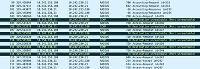
In the next example, the capture for RADIUS traffic is filtered out. You see that the ASA is the device that ends in .180 and the RADIUS server ends in .21
In this example, both RADIUS servers return a "port unreachable", 3 times in a row for each. This triggers the ASA to mark both RADIUS servers as dead within milliseconds of each other.
The Result
Each .21 address in this example was an F5 VIP address. That means that behind the VIPS were clusters of Cisco ISE nodes in the PSN persona.
The F5 returned "port unreachable" due to an F5 defect.
In this example, the Cisco TAC team successfully proved that the ASA worked as expected. That is, it sent radius packets and received 3 ports that were unreachable before, and effected the Radius Server marked failed:

Related Information


 Feedback