ASA/PIX with OSPF Configuration Example
Available Languages
Contents
Introduction
This document describes how to configure the Cisco ASA to learn routes through Open Shortest Path First (OSPF), perform authentication, and redistribution.
Refer to PIX/ASA 8.X: Configuring EIGRP on the Cisco Adaptive Security Appliance (ASA) for more information on EIGRP configuration.
Note: Asymmetric routing is not supported in ASA/PIX.
Prerequisites
Requirements
Ensure that you meet these requirements before you attempt this configuration:
-
Cisco ASA/PIX must run Version 7.x or later.
-
OSPF is not supported in multi-context mode; it is supported only in single mode.
Components Used
The information in this document is based on these software and hardware versions:
-
Cisco 5500 Series Adaptive Security Appliance (ASA) that runs software version 8.0 and later
-
Cisco Adaptive Security Device Manager (ASDM) software version 6.0 and later
The information in this document was created from the devices in a specific lab environment. All of the devices used in this document started with a cleared (default) configuration. If your network is live, make sure that you understand the potential impact of any command.
Related Products
The information in this document is also applicable to the Cisco 500 Series PIX firewall that runs software version 8.0 and later.
Conventions
Refer to the Cisco Technical Tips Conventions for more information on document conventions.
Background Information
OSPF uses a link-state algorithm in order to build and calculate the shortest path to all known destinations. Each router in an OSPF area contains an identical link-state database, which is a list of each of the router usable interfaces and reachable neighbors.
The advantages of OSPF over RIP include:
-
OSPF link-state database updates are sent less frequently than RIP updates, and the link-state database is updated instantly rather than gradually as stale information is timed out.
-
Routing decisions are based on cost, which is an indication of the overhead required to send packets across a certain interface. The security appliance calculates the cost of an interface based on link bandwidth rather than the number of hops to the destination. The cost can be configured to specify preferred paths.
The disadvantage of shortest path first algorithms is that they require a lot of CPU cycles and memory.
The security appliance can run two processes of OSPF protocol simultaneously, on different sets of interfaces. You might want to run two processes if you have interfaces that use the same IP addresses (NAT allows these interfaces to coexist, but OSPF does not allow overlapping addresses). Or you might want to run one process on the inside, and another on the outside, and redistribute a subset of routes between the two processes. Similarly, you might need to segregate private addresses from public addresses.
You can redistribute routes into an OSPF routing process from another OSPF routing process, a RIP routing process, or from static and connected routes configured on OSPF-enabled interfaces.
The security appliance supports these OSPF features:
-
Support of intra-area, interarea, and external (Type I and Type II) routes.
-
Support of a virtual link.
-
OSPF LSA flooding.
-
Authentication to OSPF packets (both password and MD5 authentication).
-
Support for configuring the security appliance as a designated router or a designated backup router. The security appliance also can be set up as an ABR. However, the ability to configure the security appliance as an ASBR is limited to default information only (for example, injecting a default route).
-
Support for stub areas and not-so-stubby-areas.
-
Area boundary router type-3 LSA filtering.
Configure
In this section, you are presented with the information to configure the features described in this document.
Note: Use the Command Lookup Tool (registered customers only) in order to obtain more information on the commands used in this section.
Network Diagram
This document uses this network setup:
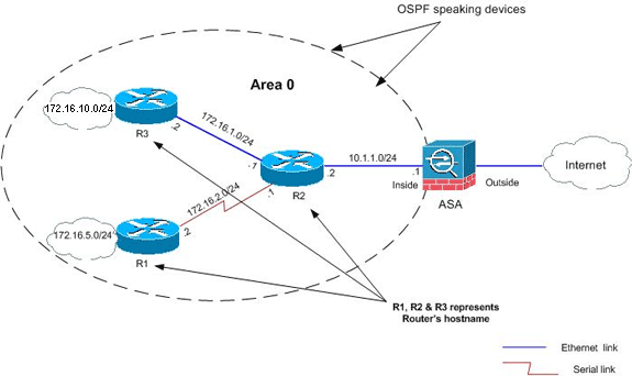
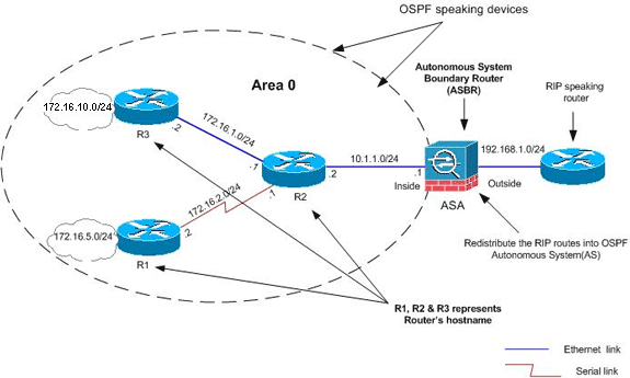
In this network topology, the Cisco ASA inside interface IP address is 10.1.1.1/24. The goal is to configure OSPF on the Cisco ASA in order to learn routes to the internal networks (172.16.1.0/24, 172.16.2.0/24, 172.16.5.0/24 and 172.16.10.0/24) dynamically through the adjacent router (R2). R2 learns the routes to remote internal networks through the other two routers (R1 and R3).
Configurations
This document uses these configurations:
ASDM Configuration
Adaptive Security Device Manager (ASDM) is a browser-based application used to configure and monitor the software on security appliances. ASDM is loaded from the security appliance, and then used to configure, monitor, and manage the device. You can also use the ASDM Launcher (Windows only) in order to launch the ASDM application faster than the Java applet. This section describes the information you need to configure the features described in this document with ASDM.
Complete these steps in order to configure OSPF in the Cisco ASA:
-
Log in to the Cisco ASA with ASDM.
-
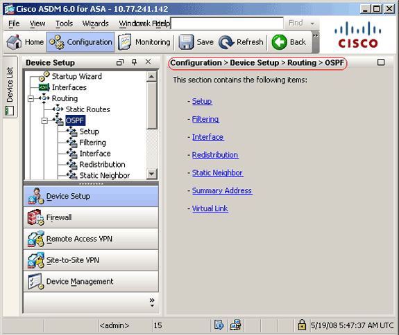
Navigate to the Configuration > Device Setup > Routing > OSPF area of the ASDM interface, as shown in this image.
-
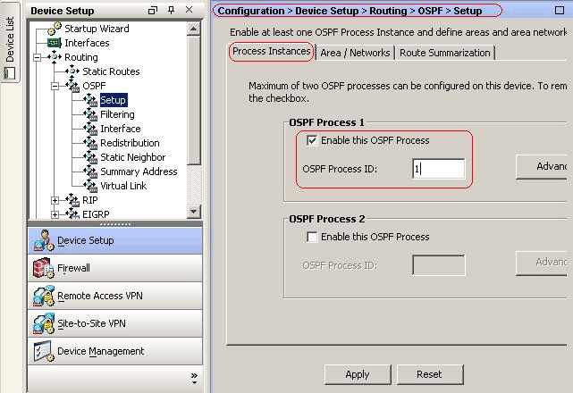
Enable the OSPF routing process on the Setup > Process Instances tab, as shown in this image. In this example, the OSPF ID process is 1.
-
You can click Advanced on the Setup > Process Instances tab in order to configure optional advanced OSPF routing process parameters. You can edit process-specific settings, such as the Router ID, Adjacency Changes, Administrative Route Distances, Timers, and Default Information Originate settings.
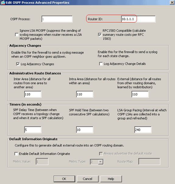
This list describes each field:
-
OSPF Process—Displays the OSPF process you are configuring. You cannot change this value.
-
Router ID—In order to use a fixed router ID, enter a router ID in IP address format in the Router ID field. If you leave this value blank, the highest-level IP address on the security appliance is used as the router ID.
In this example, the Router ID is statically configured with the IP address of the inside interface (10.1.1.1).
-
Ignore LSA MOSPF—Check this check box in order to suppress the sending of system log messages when the security appliance receives type 6 (MOSPF) LSA packets. This setting is unchecked by default.
-
RFC 1583 Compatible—Check this check box in order to calculate summary route costs per RFC 1583. Uncheck this check box in order to calculate summary route costs per RFC 2328. In order to minimize the chance of routing loops, all OSPF devices in an OSPF routing domain should have RFC compatibility set identically. This setting is selected by default.
-
Adjacency Changes—Contains settings that define the adjacency changes that cause system log messages to be sent.
-
Log Adjacency Changes—Check this check box in order to cause the security appliance to send a system log message whenever an OSPF neighbor goes up or down. This setting is selected by default.
-
Log Adjacency Changes Detail—Check this check box in order to cause the security appliance to send a system log message whenever any state change occurs, not just when a neighbor goes up or down. This setting is unchecked by default.
-
-
Administrative Route Distances—Contains the settings for the administrative distances of routes based on the route type.
-
Inter Area—Sets the administrative distance for all routes from one area to another. Valid values range from 1 to 255. The default value is 100.
-
Intra Area—Sets the administrative distance for all routes within an area. Valid values range from 1 to 255. The default value is 100.
-
External—Sets the administrative distance for all routes from other routing domains that are learned through redistribution. Valid values range from 1 to 255. The default value is 100.
-
-
Timers—Contains the settings used to configure LSA pacing and SPF calculation timers.
-
SPF Delay Time—Specifies the time between when OSPF receives a topology change and when the SPF calculation starts. Valid values range from 0 to 65535. The default value is 5.
-
SPF Hold Time—Specifies the hold time between consecutive SPF calculations.Valid values range from 1 to 65534. The default value is 10.
-
LSA Group Pacing—Specifies the interval at which LSAs are collected into a group and refreshed, checksummed, or aged. Valid values range from 10 to 1800. The default value is 240.
-
-
Default Information Originate—Contains the settings used by an ASBR to generate a default external route into an OSPF routing domain.
-
Enable Default Information Originate—Check this check box in order to enable the generation of the default route into the OSPF routing domain.
-
Always advertise the default route—Check this check box in order to always advertise the default route. This option is unchecked by default.
-
Metric Value—Specifies the OSPF default metric. Valid values range from 0 to 16777214. The default value is 1.
-
Metric Type—Specifies the external link type associated with the default route advertised into the OSPF routing domain. Valid values are 1 or 2, indicating a Type 1 or a Type 2 external route. The default value is 2.
-
Route Map—(Optional) The name of the route map to apply. The routing process generates the default route if the route map is satisfied.
-
-
-
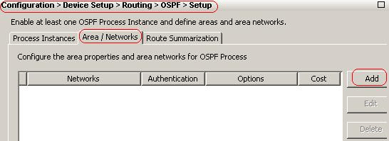
After you complete the previous steps, define the networks and interfaces that participate in OSPF routing on the Setup > Area/Networks tab, and then click Add as shown in this image:
The Add OSPF Area dialog box appears.
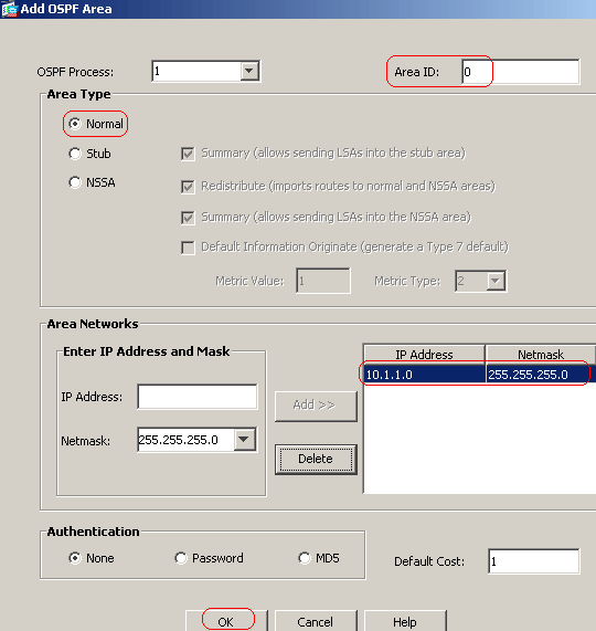
In this example, the only network that is added is the inside network (10.1.1.0/24) since OSPF is enabled only on the inside interface.
Note: Only interfaces with an IP address that fall within the defined networks participate in the OSPF routing process.
-
Click OK.
This list describes each fields:
-
OSPF Process—When you add a new area, choose the ID for the OSPF process . If there is only one OSPF process enabled on the security appliance, then that process is selected by default. When you edit an existing area, you cannot change the OSPF process ID.
-
Area ID—When you add a new area, enter the area ID. You can specify the area ID as either a decimal number or an IP address. Valid decimal values range from 0 to 4294967295. You cannot change the area ID when you edit an existing area.
In this example, Area ID is 0.
-
Area Type—Contains the settings for the type of area being configured.
-
Normal—Choose this option in order to make the area a standard OSPF area. This option is selected by default when you first create an area.
-
Stub—Choose this option in order to make the area a stub area. Stub areas do not have any routers or areas beyond it. Stub areas prevent AS External LSAs (type 5 LSAs) from being flooded into the stub area. When you create a stub area, you can uncheck the Summary check box in order to to prevent summary LSAs (type 3 and 4) from being flooded into the area.
-
Summary—When the area being defined is a stub area, uncheck this check box in order to prevent LSAs from being sent into the stub area. This check box is selected by default for stub areas.
-
NSSA—Choose this option in order to make the area a not-so-stubby area. NSSAs accept type 7 LSAs. When you create an NSSA, you can uncheck the Summary check box in order to prevent summary LSAs from being flooded into the area. In addition, you can uncheck the Redistribute check box and enable Defautl Information Originate in order to disable route redistribution.
-
Redistribute—Uncheck this check box in order to prevent routes from being imported into the NSSA. This check box is selected by default.
-
Summary—When the area being defined is an NSSA, uncheck this check box in order to prevent LSAs from being sent into the stub area. This check box is selected by default for NSSAs.
-
Default Information Originate—Check this check box in order to generate a type 7 default into the NSSA. This check box is unchecked by default.
-
Metric Value—Enter a value in order to specify the OSPF metric value for the default route. Valid values range from 0 to 16777214. The default value is 1.
-
Metric Type—Choose a value in order to specify the OSPF metric type for the default route. The choices are 1 (type 1) or 2 (type 2). The default value is 2.
-
-
Area Networks—Contains the settings that define an OSPF area.
-
Enter IP Address and Mask—Contains the settings used to define the networks in the area.
-
IP Address—Enter the IP address of the network or host to be added to the area. Use 0.0.0.0 with a netmask of 0.0.0.0 to create the default area. You can use 0.0.0.0 in only one area.
-
Netmask—Choose the network mask for the IP address or host to be added to the area. If you add a host, choose the 255.255.255.255 mask.
In this example, 10.1.1.0/24 is the network to be configured.
-
-
Add—Adds the network defined in the Enter IP Address and Mask area to the area. The added network appears in the Area Networks table.
-
Delete—Deletes the selected network from the Area Networks table.
-
Area Networks—Displays the networks defined for the area.
-
IP Address—Displays the IP address of the network.
-
Netmask—Displays the network mask for the network.
-
-
Authentication—Contains the settings for OSPF area authentication.
-
None—Choose this option in order to disable OSPF area authentication. This is the default setting.
-
Password—Choose this option in order to use a clear text password for area authentication. This option is not recommended where security is a concern.
-
MD5—Choose this option in order to use MD5 authentication.
-
-
Default Cost—Specify a default cost for the area. Valid values range from 0 to 65535. The default value is 1.
-
-
Click Apply.
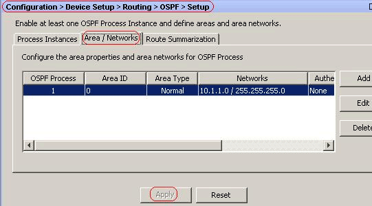
-
Optionally, you can define route filters on the Filter Rules pane. Route filtering provides more control over the routes that are allowed to be sent or received in OSPF updates.
-
You can optionally configure route redistribution. The Cisco ASA can redistribute routes discovered by RIP and EIGRP into the OSPF routing process. You can also redistribute static and connected routes into the OSPF routing process. Define route redistribution on the Redistribution pane.
-
OSPF hello packets are sent as multicast packets. If an OSPF neighbor is located across a nonbroadcast network, you must manually define that neighbor. When you manually define an OSPF neighbor, hello packets are sent to that neighbor as unicast messages. In order to define static OSPF neighbors, go to the Static Neighbor pane.
-
Routes learned from other routing protocols can be summarized. The metric used to advertise the summary is the smallest metric of all the more specific routes. Summary routes help reduce the size of the routing table.
Using summary routes for OSPF causes an OSPF ASBR to advertise one external route as an aggregate for all redistributed routes that are covered by the address. Only routes from other routing protocols that are being redistributed into OSPF can be summarized.
-
In the Virtual link pane, you can add an area to an OSPF network, and it is not possible to connect the area directly to the backbone area; you must create a virtual link. A virtual link connects two OSPF devices that have a common area, called the transit area. One of the OSPF devices must be connected to the backbone area.
Configure OSPF Authentication
The Cisco ASA supports MD5 authentication of routing updates from the OSPF routing protocol. The MD5 keyed digest in each OSPF packet prevents the introduction of unauthorized or false routing messages from unapproved sources. The addition of authentication to your OSPF messages ensures that your routers and the Cisco ASA only accept routing messages from other routing devices that are configured with the same pre-shared key. Without this authentication configured, if someone introduces another routing device with different or contrary route information onto the network, the routing tables on your routers or Cisco ASA can become corrupt, and a denial of service attack can ensue. When you add authentication to the EIGRP messages sent between your routing devices (which includes the ASA), it prevents the purposeful or accidental addition of another router to the network and any problem.
OSPF route authentication is configured on a per-interface basis. All OSPF neighbors on interfaces configured for OSPF message authentication must be configured with the same authentication mode and key for adjacencies to be established.
Complete these steps in order to enable OSPF MD5 authentication on the Cisco ASA:
-
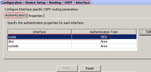
On ASDM, navigate to Configuration > Device Setup > Routing > OSPF > Interface, and then click Authentication tab as shown in this image.
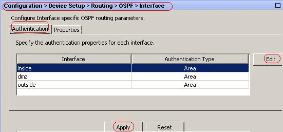
In this case, OSPF is enabled on the inside interface.
-
Choose the inside interface, and click Edit.
-
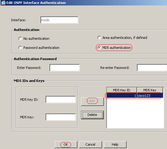
Under Authentication, choose MD5 authentication, and add more information about authentication parameters here.
In this case, the preshared key is cisco123, and the key ID is 1.
-
Click OK, and then click Apply.
Cisco ASA CLI Configuration
| Cisco ASA |
|---|
ciscoasa#show running-config : Saved : ASA Version 8.0(2) ! hostname ciscoasa enable password 8Ry2YjIyt7RRXU24 encrypted names !--- Inside interface configuration interface Ethernet0/1 nameif inside security-level 100 ip address 10.1.1.1 255.255.255.0 ospf cost 10 !--- OSPF authentication is configured on the inside interface ospf message-digest-key 1 md5 <removed> ospf authentication message-digest ! !--- Outside interface configuration interface Ethernet0/2 nameif outside security-level 0 ip address 192.168.1.2 255.255.255.0 ospf cost 10 ! !--- Output Suppressed icmp unreachable rate-limit 1 burst-size 1 asdm image disk0:/asdm-602.bin no asdm history enable arp timeout 14400 ! !--- OSPF Configuration router ospf 1 network 10.1.1.0 255.255.255.0 area 0 log-adj-changes ! !--- This is the static default gateway configuration in order to reach Internet route outside 0.0.0.0 0.0.0.0 192.168.1.1 1 ciscoasa# |
Cisco IOS Router (R2) CLI Configuration
| Cisco IOS Router (R2) |
|---|
!--- Interface that connects to the Cisco ASA. !--- Notice the OSPF authentication parameters interface Ethernet0 ip address 10.1.1.2 255.255.255.0 ip ospf authentication message-digest ip ospf message-digest-key 1 md5 cisco123 !--- Output Suppressed !--- OSPF Configuration router ospf 1 log-adjacency-changes network 10.1.1.0 0.0.0.255 area 0 network 172.16.1.0 0.0.0.255 area 0 network 172.16.2.0 0.0.0.255 area 0 |
Cisco IOS Router (R1) CLI Configuration
| Cisco IOS Router (R1) |
|---|
!--- Output Suppressed !--- OSPF Configuration router ospf 1 log-adjacency-changes network 172.16.5.0 0.0.0.255 area 0 network 172.16.2.0 0.0.0.255 area 0 |
Cisco IOS Router (R3) CLI Configuration
| Cisco IOS Router (R3) |
|---|
!--- Output Suppressed !--- OSPF Configuration router ospf 1 log-adjacency-changes network 172.16.1.0 0.0.0.255 area 0 network 172.16.10.0 0.0.0.255 area 0 |
Redistribute into OSPF with ASA
As mentioned earlier, you can redistribute routes into an OSPF routing process from another OSPF routing process, a RIP routing process, or from static and connected routes configured on OSPF-enabled interfaces.
In this example, redistributing the RIP routes into OSPF with the network diagram as shown:
ASDM Configuration
-
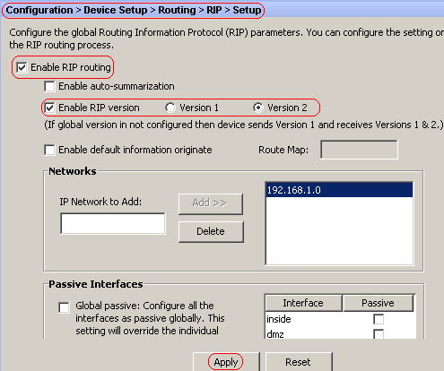
Choose Configuration > Device Setup > Routing > RIP > Setup in order to enable RIP, and add the network 192.168.1.0 as shown in this image.
-
Click Apply.
-
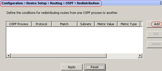
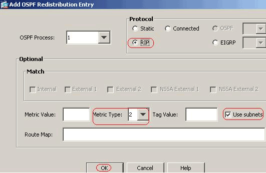
Choose Configuration > Device Setup > Routing > OSPF > Redistribution > Add in order to redistribute RIP routes into OSPF.
-
Click OK, and then click Apply.
Equivalent CLI Configuration
| CLI Configuration of ASA for Redistribute RIP into OSPF AS |
|---|
router ospf 1 network 10.1.1.0 255.255.255.0 area 0 log-adj-changes redistribute rip subnets router rip network 192.168.1.0 |
You can see the routing table of the neighbor IOS Router(R2) after redistributing RIP routes into OSPF AS.
R2#show ip route
Codes: C - connected, S - static, I - IGRP, R - RIP, M - mobile, B - BGP
       D - EIGRP, EX - EIGRP external, O - OSPF, IA - OSPF inter area
       N1 - OSPF NSSA external type 1, N2 - OSPF NSSA external type 2
       E1 - OSPF external type 1, E2 - OSPF external type 2, E - EGP
       i - IS-IS, su - IS-IS summary, L1 - IS-IS level-1, L2 - IS-IS level-2
       ia - IS-IS inter area, * - candidate default, U - per-user static route
       o - ODR, P - periodic downloaded static route

Gateway of last resort is not set

     172.16.0.0/16 is variably subnetted, 4 subnets, 2 masks
O       172.16.10.1/32 [110/11] via 172.16.1.2, 01:17:29, Ethernet1
O       172.16.5.1/32 [110/65] via 172.16.2.2, 01:17:29, Serial1
C       172.16.1.0/24 is directly connected, Ethernet1
C       172.16.2.0/24 is directly connected, Serial1
     10.0.0.0/24 is subnetted, 1 subnets
C       10.1.1.0 is directly connected, Ethernet0
O E2 192.168.1.0/24 [110/20] via 10.1.1.1, 01:17:29, Ethernet0

!--- Redistributed route adverstied by Cisco ASA
Verify
Complete these steps to verify your configuration:
-
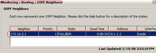
On ASDM, you can navigate to Monitoring > Routing > OSPF Neighbors to see each of the OSPF neighbors. This image shows the inside router (R2) as an active neighbor. You can also see the interface where this neighbor resides, neighbor router ID, state, and dead time.
-
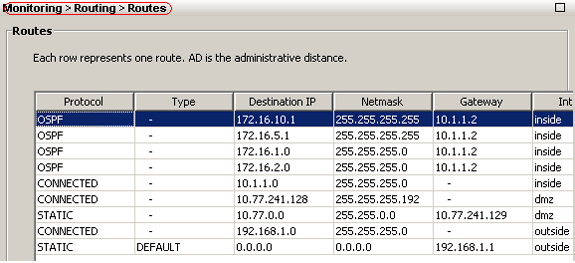
Additionally, you can verify the routing table if you navigate to Monitoring > Routing > Routes. In this image, the 172.16.1.0/24, 172.16.2.0/24, 172.16.5.0/24, and 172.16.10.0/24 networks are learned through R2 (10.1.1.2).
-
From the CLI, you can use the show route command in order to get the same output.
ciscoasa#show route Codes: C - connected, S - static, I - IGRP, R - RIP, M - mobile, B - BGP D - EIGRP, EX - EIGRP external, O - OSPF, IA - OSPF inter area N1 - OSPF NSSA external type 1, N2 - OSPF NSSA external type 2 E1 - OSPF external type 1, E2 - OSPF external type 2, E - EGP i - IS-IS, L1 - IS-IS level-1, L2 - IS-IS level-2, ia - IS-IS inter area * - candidate default, U - per-user static route, o - ODR P - periodic downloaded static route Gateway of last resort is 192.168.1.1 to network 0.0.0.0 O 172.16.10.1 255.255.255.255 [110/21] via 10.1.1.2, 0:00:06, inside O 172.16.5.1 255.255.255.255 [110/75] via 10.1.1.2, 0:00:06, inside O 172.16.1.0 255.255.255.0 [110/20] via 10.1.1.2, 0:00:06, inside O 172.16.2.0 255.255.255.0 [110/74] via 10.1.1.2, 0:00:06, inside C 10.1.1.0 255.255.255.0 is directly connected, inside C 10.77.241.128 255.255.255.192 is directly connected, dmz S 10.77.0.0 255.255.0.0 [1/0] via 10.77.241.129, dmz C 192.168.1.0 255.255.255.0 is directly connected, outside S* 0.0.0.0 0.0.0.0 [1/0] via 192.168.1.1, outside -
You can also use the show ospf database command in order to obtain information about the learned networks and ospf topology.
ciscoasa#show ospf database OSPF Router with ID (192.168.1.2) (Process ID 1) Router Link States (Area 0) Link ID ADV Router Age Seq# Checksum Link count 172.16.1.2 172.16.1.2 123 0x80000039 0xfd1d 2 172.16.2.1 172.16.2.1 775 0x8000003c 0x9b42 4 172.16.5.1 172.16.5.1 308 0x80000038 0xb91b 3 192.168.1.2 192.168.1.2 1038 0x80000037 0x29d7 1 Net Link States (Area 0) Link ID ADV Router Age Seq# Checksum 10.1.1.1 192.168.1.2 1038 0x80000034 0x72ee 172.16.1.1 172.16.2.1 282 0x80000036 0x9e68 -
The show ospf neighbors command is also useful in order to verify the active neighbors and correspondent information. This example shows the same information you obtained from ASDM on step 1.
ciscoasa#show ospf neighbor


Neighbor ID     Pri   State           Dead Time   Address         Interface
172.16.2.1        1   FULL/BDR        0:00:36     10.1.1.2        inside
Troubleshoot
This section provides information that might facilitate troubleshooting OSPF issues.
Static Neighbor Configuration for Point-to-Point Network
If you have configured OSPF network point-to-point non-broadcast on the ASA, you must define static OSPF neighbors to advertise OSPF routes over a point-to-point, non-broadcast network. Refer to Defining Static OSPF Neighbors for more information.
Troubleshooting Commands
The Output Interpreter Tool (registered customers only) (OIT) supports certain show commands. Use the OIT to view an analysis of show command output.
Note: Refer to Important Information on Debug Commands before you use debug commands.
-
debug ospf events— Enables the debugging of OSPF events.
ciscoasa(config)#debug ospf events
OSPF events debugging is on
ciscoasa(config)# int e0/1
ciscoasa(config-if)# no shu
ciscoasa(config-if)#
OSPF: Interface inside going Up
OSPF: Send with youngest Key 1
OSPF: Rcv hello from 172.16.2.1 area 0 from inside 10.1.1.2
OSPF: 2 Way Communication to 172.16.2.1 on inside, state 2WAY
OSPF: Backup seen Event before WAIT timer on inside
OSPF: DR/BDR election on inside
OSPF: Elect BDR 172.16.2.1
OSPF: Elect DR 172.16.2.1
       DR: 172.16.2.1 (Id)   BDR: 172.16.2.1 (Id)
OSPF: Send DBD to 172.16.2.1 on inside seq 0x1abd opt 0x2 flag 0x7 len 32
OSPF: Send with youngest Key 1
OSPF: End of hello processing
OSPF: Rcv hello from 172.16.2.1 area 0 from inside 10.1.1.2
OSPF: End of hello processing
OSPF: Rcv DBD from 172.16.2.1 on inside seq 0x12f3 opt 0x42 flag 0x7 len 32  mtu
 1500 state EXSTART
OSPF: First DBD and we are not SLAVE
OSPF: Rcv DBD from 172.16.2.1 on inside seq 0x1abd opt 0x42 flag 0x2 len 152  mt
u 1500 state EXSTART
OSPF: NBR Negotiation Done. We are the MASTER
OSPF: Send DBD to 172.16.2.1 on inside seq 0x1abe opt 0x2 flag 0x3 len 132
OSPF: Send with youngest Key 1
OSPF: Send with youngest Key 1
OSPF: Database request to 172.16.2.1
OSPF: sent LS REQ packet to 10.1.1.2, length 12
OSPF: Rcv DBD from 172.16.2.1 on inside seq 0x1abe opt 0x42 flag 0x0 len 32  mtu
 1500 state EXCHANGE
OSPF: Send DBD to 172.16.2.1 on inside seq 0x1abf opt 0x2 flag 0x1 len 32
OSPF: Send with youngest Key 1
OSPF: Send with youngest Key 1
OSPF: Rcv DBD from 172.16.2.1 on inside seq 0x1abf opt 0x42 flag 0x0 len 32  mtu
 1500 state EXCHANGE
OSPF: Exchange Done with 172.16.2.1 on inside
OSPF: Synchronized with 172.16.2.1 on inside, state FULL
OSPF: Send with youngest Key 1
OSPF: Send with youngest Key 1
OSPF: Rcv hello from 172.16.2.1 area 0 from inside 10.1.1.2
OSPF: Neighbor change Event on interface inside
OSPF: DR/BDR election on inside
OSPF: Elect BDR 192.168.1.2
OSPF: Elect DR 172.16.2.1
OSPF: Elect BDR 192.168.1.2
OSPF: Elect DR 172.16.2.1
       DR: 172.16.2.1 (Id)   BDR: 192.168.1.2 (Id)
OSPF: End of hello processing
OSPF: Send with youngest Key 1
OSPF: Send with youngest Key 1
OSPF: Send with youngest Key 1
OSPF: Send with youngest Key 1
OSPF: Rcv hello from 172.16.2.1 area 0 from inside 10.1.1.2
OSPF: End of hello processing
OSPF: Send with youngest Key 1
OSPF: Rcv hello from 172.16.2.1 area 0 from inside 10.1.1.2
OSPF: End of hello processing
OSPF: Send with youngest Key 1
OSPF: Rcv hello from 172.16.2.1 area 0 from inside 10.1.1.2
OSPF: End of hello processing
OSPF: Send with youngest Key 1
OSPF: Rcv hello from 172.16.2.1 area 0 from inside 10.1.1.2
OSPF: End of hello processing
Note: Refer to the debug ospf section of the Cisco Security Appliance Command Reference, Version 8.0 for more information on various commands which are useful for troubleshooting the problem.
Related Information
Contact Cisco
- Open a Support Case

- (Requires a Cisco Service Contract)


 Feedback