ASA 8.2: Port Redirection (Forwarding) with nat, global, static, and access-list Commands Using ASDM
Available Languages
Contents
Introduction
This document describes how the port redirection works on Cisco Adaptive Security Appliance (ASA) using ASDM. It deals with the access control of the traffic through the ASA and how translation rules work.
Prerequisites
Requirements
Cisco recommends that you have knowledge of these topics:
Components Used
The information in this document is based on these software and hardware versions:
-
Cisco 5500 Series ASA version 8.2
-
Cisco ASDM version 6.3
Note: This configuration works fine from Cisco ASA software version 8.0 to 8.2 only, because there are no major changes in the NAT functionality.
The information in this document was created from the devices in a specific lab environment. All of the devices used in this document started with a cleared (default) configuration. If your network is live, make sure that you understand the potential impact of any command.
Conventions
Refer to Cisco Technical Tips Conventions for more information on document conventions.
Network Diagram
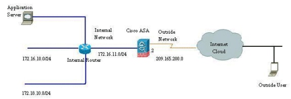
The IP addressing schemes used in this configuration are not legally routable on the Internet. They are RFC 1918 addresses which have been used in a lab environment.
Allow Outbound Access
Outbound access describes connections from a higher security level interface to a lower security level interface. This includes connections from inside to outside, inside to Demilitarized Zones (DMZs), and DMZs to outside. This can also include connections from one DMZ to another, as long as the connection source interface has a higher security level than the destination.
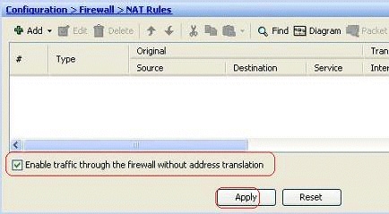
No connection can pass through the Security Appliance without a translation rule configured. This feature is called nat-control . The image shown here depicts how to disable this through ASDM in order to allow connections through the ASA without any address translation. However, if you have any translation rule configured, then disabling this feature does not remain valid for all the traffic and you will need to explicitly exempt the networks from address translation.
Allow Inside Hosts Access to Outside Networks with NAT
You could allow a group of inside hosts/networks to access the outside world by configuring the dynamic NAT rules. In order to accomplish this, you need to select the real address of the hosts/networks to be given access and they then have to be mapped to a pool of translated IP addresses.
Complete these steps in order to allow inside hosts access to outside networks with NAT:
-
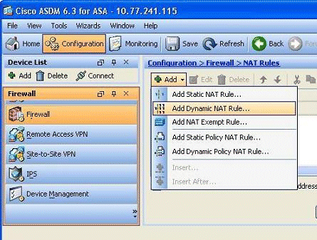
Go to Configuration > Firewall > NAT Rules, click Add, and then choose the Add Dynamic NAT Rule option in order to configure a dynamic NAT rule.
-
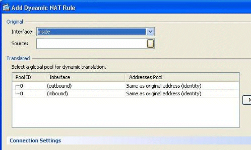
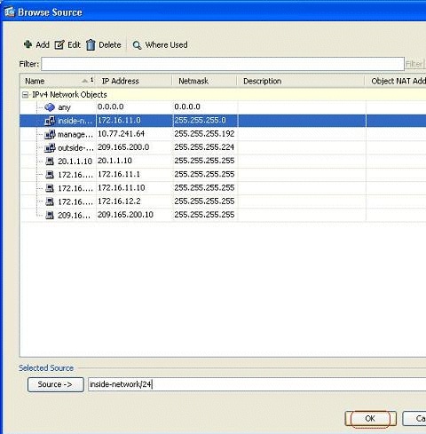
Choose the name of the interface to which the real hosts are connected. Choose the real IP address of the hosts/networks using the Details button in the Source field.
-
In this example, the entire inside-network has been selected. Click OK in order to complete the selection.
-
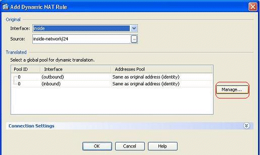
Click Manage in order to select the pool of IP addresses to which the real network will be mapped.
-
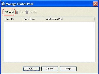
Click Add in order to open the Add Global Address Pool window.
-
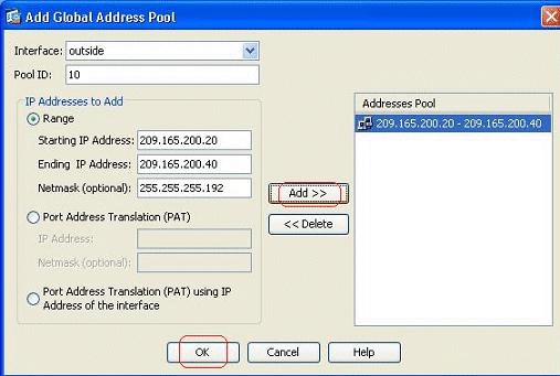
Choose the Range option and specify the Starting and Ending IP Addresses along with the egress interface. Also, specify a unique pool ID and click Add in order to add these to the address pool. Click OK in order to return to the Manage Global Pool window.
-
Click OK in order to return to the Add Dynamic NAT Rule window.
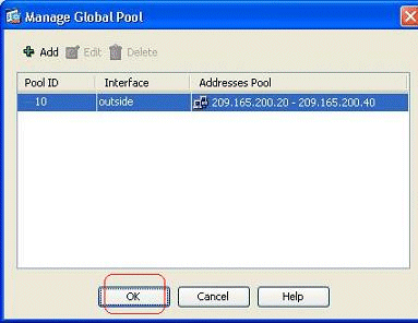
-
Click OK in order to complete the Dynamic NAT Rule configuration.
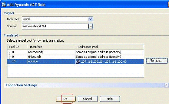
-
Click Apply for the changes to take effect.
Note: The Enable traffic through the firewall without address translation option is unchecked.

This is the equivalent CLI output for this ASDM configuration:
nat-control
global (outside) 10 209.165.200.20-209.165.200.40 netmask 255.255.255.192
nat (inside) 10 172.16.11.0 255.255.255.0
As per this configuration, the hosts in the 172.16.11.0 network will get translated to any IP address from the NAT pool, 209.165.200.20-209.165.200.40. Here, the NAT pool ID is very important. You could assign the same NAT pool to another internal/dmz network. If the mapped pool has fewer addresses than the real group, you could run out of addresses if the amount of traffic is more than expected. As a result, you could try implementing PAT or you could try to edit the existing address pool to extend it.
Note: While making any modification to the existing translation rule, note that you need to use the clear xlate command for those modifications to take effect. Otherwise, the previous existing connection will remain there in the connection table until they time-out. Be cautious when using the clear xlate command, because it immediately terminates the existing connections.
Allow Inside Hosts Access to Outside Networks with PAT
If you want inside hosts to share a single public address for translation, use PAT. If the global statement specifies one address, that address is port translated. The ASA allows one port translation per interface and that translation supports up to 65,535 active xlate objects to the single global address.
Complete these steps in order to allow inside hosts access to outside networks with PAT:
-
Go to Configuration > Firewall > NAT Rules, click Add, and then choose the Add Dynamic NAT Rule option in order to configure a dynamic NAT rule.
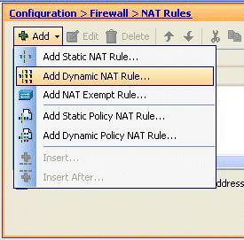
-
Choose the name of the interface to which the real hosts are connected. Choose the real IP address of the hosts/networks using the Details button in the Source field, and choose inside-network. Click Manage in order to define the Translated address information.
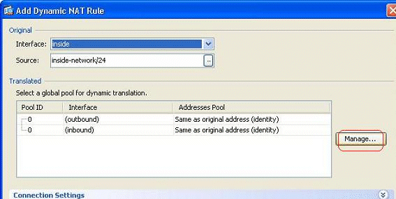
-
Click Add.
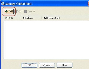
-
Choose the Port Address Translation (PAT) using IP address of the interface option, and click Add in order to add it to the address pool. Do not forget to assign a unique ID for this NAT address pool.
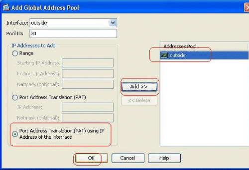
-
Shown here is the configured address pool with the outside interface as the only available address in that pool. Click OK in order to return to the Add Dynamic NAT Rule window.
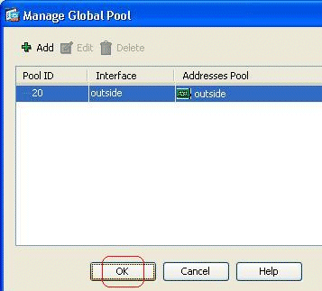
-
Click OK.
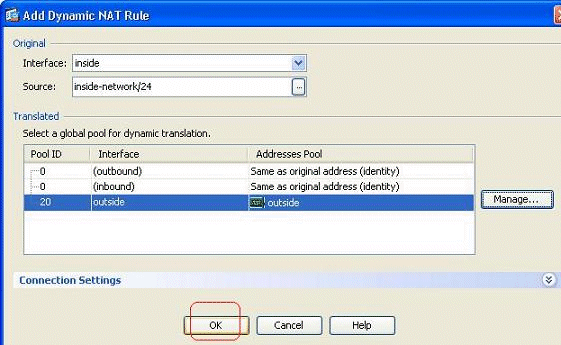
-
The configured dynamic NAT rule is shown here in the Configuration > Firewall > NAT Rules pane.
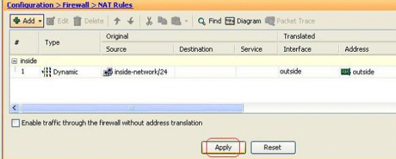
This is the equivalent CLI output for this PAT configuration:
global (outside) 20 interface
nat (inside) 20 172.16.11.0 255.255.255.0
Restrict Inside Hosts Access to Outside Networks
When no access rules are defined, the users from a higher-security interface can access any resources associated with a lower-security interface. To restrict certain users from accessing certain resources, use access rules in the ASDM. This example describes how to allow a single user to access outside resources (with FTP, SMTP, POP3, HTTPS, and WWW) and to restrict all others from accessing the outside resources.
Note: There will be an "Implicit Deny" rule at the end of every access-list.
Complete these steps:
-
Go to Configuration > Firewall > Access Rules, click Add, and choose the Add Access Rule option in order to create a new access-list entry.
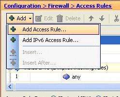
-
Choose the Source IP address that is to be permitted in the Source field. Choose any as the Destination, inside as the Interface, and Permit as the Action. Lastly, click the Details button in the Service field in order to create a TCP service group for the required ports.
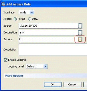
-
Click Add, and then choose the TCP Service Group option.
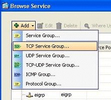
-
Enter a name for this group. Choose each of the required ports, and click Add in order to move them to the Members in Group field.
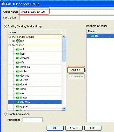
-
You should see all of the selected ports in the right-hand field. Click OK in order to complete the service ports selecting process.
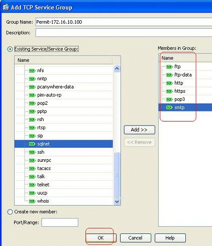
-
You can see the configured TCP service group here. Click OK.
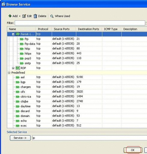
-
Click OK in order to complete the configuration.
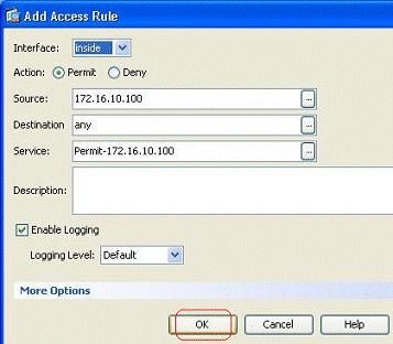
-
The configured access rule can be seen under the inside interface in the Configuration > Firewall > Access Rules pane.
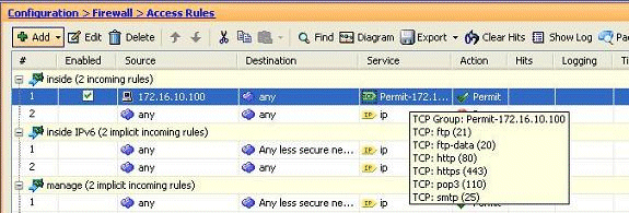
-
For ease of use, you could also edit the TCP service-group directly on the right-hand pane in the Services tab. Click Edit in order to modify this service-group directly.
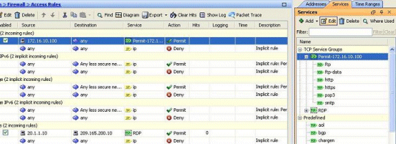
-
It again redirects to the Edit TCP Service Group window. Perform modifications based on your requirements, and click OK in order to save the changes.
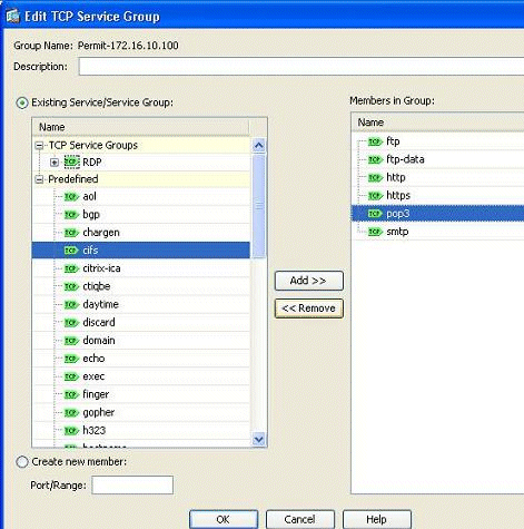
-
Shown here is a complete view of the ASDM:

This is the equivalent CLI configuration:
object-group service Permit-172.16.10.100 TCP
 port-object eq ftp
 port-object eq ftp-data
 port-object eq www
 port-object eq https
 port-object eq pop3
 port-object eq smtp
!
access-list inside_access_in extended permit TCP host 172.16.10.100 any
    object-group Permit-172.16.10.100
!
access-group inside_access_in in interface inside
!
For complete information on implementing the access control, refer to Add or Modify an Access List through the ASDM GUI.
Allow Traffic between Interfaces with Same Security Level
This section describes how to enable traffic within interfaces that have the same security levels.
These instructions describe how to enable intra-interface communication.
This will be helpful for VPN traffic that enters an interface, but is then routed out the same interface. The VPN traffic might be unencrypted in this case, or it might be re-encrypted for another VPN connection. Go to Configuration > Device Setup > Interfaces, and choose the Enable traffic between two or more hosts connected to the same interface option.
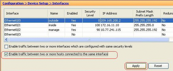
These instructions describe how to enable inter-interface communication.
This is useful to permit communication between interfaces with equal security levels. Go to Configuration > Device Setup > Interfaces, and choose the Enable traffic between two or more interfaces which are configured with same security levels option.
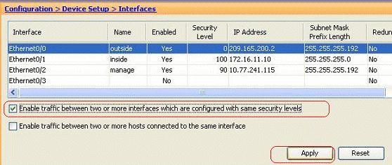
This is the equivalent CLI for both of these settings:
same-security-traffic permit intra-interface
same-security-traffic permit inter-interface
Allow Untrusted Hosts Access to Hosts on Your Trusted Network
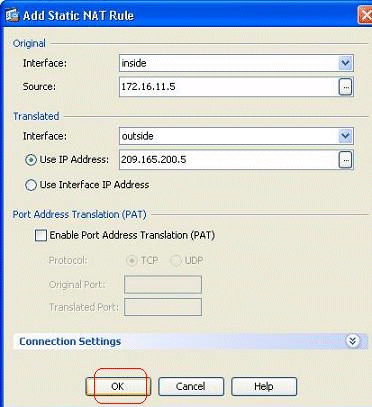
This can be achieved through applying a static NAT translation and an access-rule to permit those hosts. You require to configure this whenever an outside user would like to access any server that sits in your internal network. The server in the internal network will have a private IP address which is not routable on the Internet. As a result, you need to translate that private IP address to a public IP address through a static NAT rule. Suppose you have an internal server (172.16.11.5). In order to make this work, you need to translate this private server IP to a public IP. This example describes how to implement the bi-directional static NAT to translate 172.16.11.5 to 209.165.200.5.
The section on allowing the outside user to access this web server by implementing an access rule is not shown here. A brief CLI snippet is shown here for your understanding:
access-list 101 permit TCP any host 209.165.200.5
For more information, refer to Add or Modify an Access List through the ASDM GUI.
Note: Specifying the keyword "any" allows any user from the outside world to access this server. Also, if it is not specified for any service ports, the server can be accessed on any service port as those stay open. Use caution when you implement, and you are advised to limit the permission to the individual outside user and also to the required port on the server.
Complete these steps in order to configure the static NAT:
-
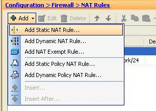
Go to Configuration > Firewall > NAT Rules, click Add, and choose Add Static NAT Rule.
-
Specify the Original IP address and the Translated IP address along with their associated interfaces, and click OK.
-
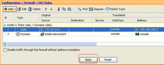
You can see the configured static NAT entry here. Click Apply in order to send this to the ASA.
This is a brief CLI example for this ASDM configuration:
!
static (inside,outside) 209.165.200.5 172.16.11.5 netmask 255.255.255.255
!
Disable NAT for Specific Hosts/Networks
When you need to exempt specific hosts or networks from NAT, add a NAT Exempt Rule to disable the address translation. This allows both translated and remote hosts to initiate connections.
Complete these steps:
-
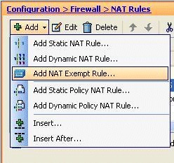
Go to Configuration > Firewall > NAT Rules, click Add, and choose Add NAT Exempt Rule.
-
Here, the inside network 172.18.10.0 has been exempted from the address translation. Make sure that the Exempt option has been selected. NAT Exempt Direction has two options:
-
Outbound traffic to lower security interfaces
-
Inbound traffic to higher security interfaces
The default option is for the outbound traffic. Click OK in order to complete the step.
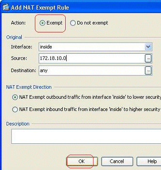
Note: When you choose the Do not exempt option, that particular host will not be exempted from NAT and a separate access rule will be added with the "deny" keyword. This is helpful in avoiding specific hosts from NAT exempt as the complete subnet, excluding these hosts, will be NAT exempted.
-
-
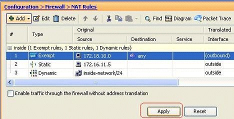
You can see the NAT exempt rule for the outbound direction here. Click Apply in order to send the configuration to the ASA.
This is the equivalent CLI output for your reference:
access-list inside_nat0_outbound extended permit ip host 172.18.10.0 any
!
nat (inside) 0 access-list inside_nat0_outbound
-
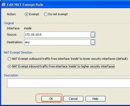
Here you can see how to edit the NAT exempt rule for its direction. Click OK for the option to take effect.
-
You can now see that the direction has been changed to inbound.
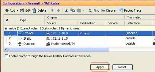
Click Apply in order to send this CLI output to the ASA:
access-list inside_nat0_outbound extended permit ip host 172.18.10.0 any
!
nat (inside) 0 access-list inside_nat0_outbound outside
Note: From this, you can see that a new keyword (outside) has been added to end of the nat 0 command. This feature is called an Outside NAT.
-
Another way to disable NAT is through implementation of Identity NAT. Identity NAT translates a host to the same IP address. Here is a Regular Static Identity NAT example, where the host (172.16.11.20) is translated to the same IP address when it is accessed from outside.
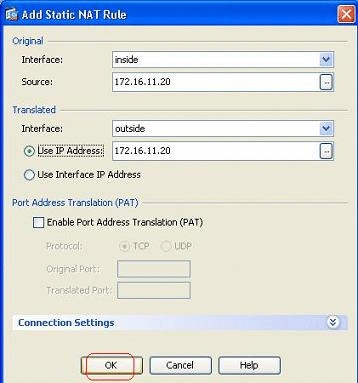
This is the equivalent CLI output:
!
static (inside,outside) 172.16.11.20 172.16.11.20 netmask 255.255.255.255
!
Port Redirection (Forwarding) with Statics
Port forwarding or port redirection is a useful feature where the outside users try to access an internal server on a specific port. In order to achieve this, the internal server, which has a private IP address, will be translated to a public IP address which in turn is allowed access for the specific port.
In this example, the outside user wants to access the SMTP server, 209.165.200.15 at port 25. This is accomplished in two steps:
-
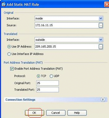
Translate the internal mail server, 172.16.11.15 on port 25, to the public IP address, 209.165.200.15 at port 25.
-
Allow access to the public mail server, 209.165.200.15 at port 25.
When the outside user tries to access the server, 209.165.200.15 at port 25, this traffic will be re-directed to the internal mail server, 172.16.11 15 at port 25.
-
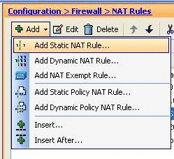
Go to Configuration > Firewall > NAT Rules, click Add, and choose Add Static NAT Rule.
-
Specify the original source and the Translated IP address along with their associated interfaces. Choose Enable Port Address Translation (PAT), specify the ports to be re-directed, and click OK.
-
The configured Static PAT rule is seen here:

This is the equivalent CLI output:
! static (inside,outside) TCP 209.165.200.15 smtp 172.16.11.15 smtp netmask 255.255.255.255 ! -
This is the access rule that allows the outside user to access the public smtp server at 209.165.200.15:

Note: Make sure to use specific hosts instead of using the any keyword in the source of the access rule.
Limit TCP/UDP Session Using Static
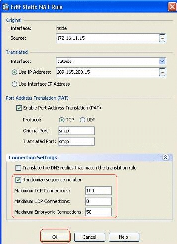
You can specify the maximum number of TCP/UDP connections by using the Static Rule. You can also specify the maximum number of embryonic connections. An embryonic connection is a connection that is a half-open state. A larger number of these will affect the performance of the ASA. Limiting these connections will prevent certain attacks like DoS and SYN to some extent. For complete mitigation, you need to define the policy in the MPF framework, which is beyond the scope of this document. For additional information on this topic, refer to Mitigating the Network Attacks.
Complete these steps:
-
Click the Connection Settings tab, and specify the values for the maximum connections for this static translation.
-
These images show the connection limits for this specific static translation:


This is the equivalent CLI output:
!
static (inside,outside) TCP 209.165.200.15 smtp 172.16.11.15 smtp netmask
    255.255.255.255 TCP 100 50
!
Time Based Access List
This section deals with implementing time-based access-lists by using the ASDM. Access rules can be applied based on time. In order to implement this, you need to define a time-range that specifies the timings by day/week/month/year. Then, you need to bind this time-range to the required access-rule. Time-range can be defined in two ways:
-
Absolute - Defines a time period with starting time and ending time.
-
Periodic - Also known as recurring. Defines a time period that occurs at specified intervals.
Note: Before you configure the time-range, make sure that the ASA has been configured with the correct date/time settings as this feature uses the system clock settings to implement. Having ASA synchronized with the NTP server will yield much better results.
Complete these steps in order to configure this feature through ASDM:
-
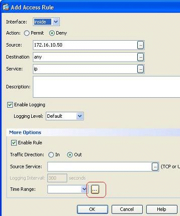
While defining the access rule, click the Details button in the Time Range field.
-
Click Add in order to create a new time-range.

-
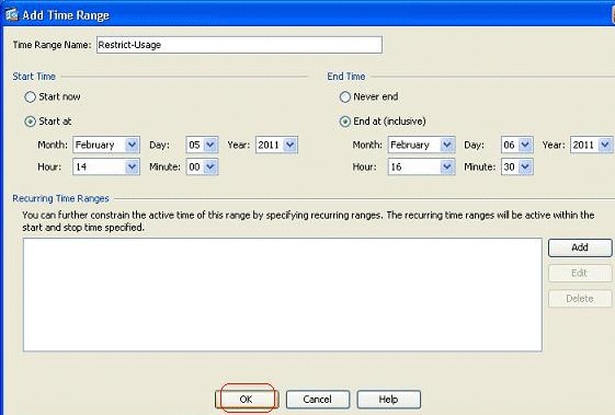
Define the name of the time range, and specify the starting time and ending time. Click OK.
-
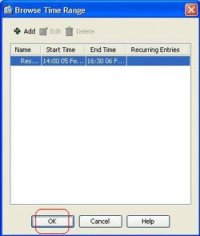
You can see the time range here. Click OK in order to return to the Add Access Rule window.
-
You can now see that the Restrict-Usage time range has been bound to this access rule.
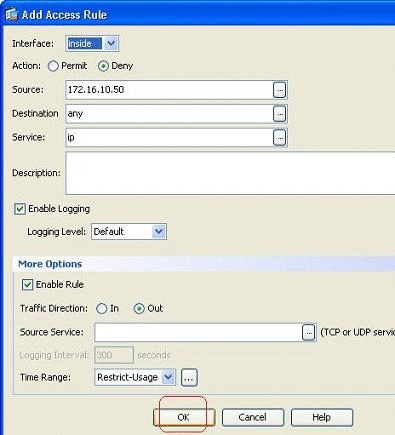
As per this access rule configuration, the user at 172.16.10.50 has been restricted from using any resources from 05/Feb/2011 2 PM to 06/Feb/2011 4.30 PM. This is the equivalent CLI output:
time-range Restrict-Usage absolute start 14:00 05 February 2011 end 16:30 06 February 2011 ! access-list inside_access_out extended deny ip host 172.16.10.50 any time-range Restrict-Usage ! access-group inside_access_out in interface inside -
Here is an example on how to specify a recurring time range. Click Add in order to define a recurring time range.
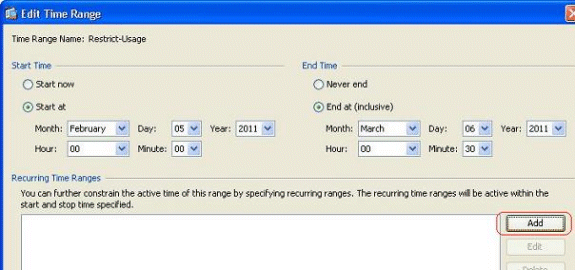
-
Specify the settings based on your requirements, and click OK in order to complete.

-
Click OK in order to return back to the Time Range window.
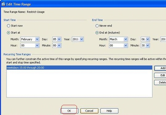
As per this configuration, the user at 172.16.10.50 has been denied access to any resources from 3 PM to 8 PM on all weekdays except Saturday and Sunday.
!
time-range Restrict-Usage
 absolute start 00:00 05 February 2011 end 00:30 06 March 2011
 periodic weekdays 15:00 to 20:00
!
access-list inside_access_out extended deny ip host 172.16.10.50 any
    time-range Restrict-Usage
!
access-group inside_access_out in interface inside
Note: If a time-range command has both absolute and periodic values specified, then the periodic commands are evaluated only after the absolute start time is reached, and are not further evaluated after the absolute end time is reached.
Related Information
Revision History
| Revision | Publish Date | Comments |
|---|---|---|
1.0 |
30-May-2011 |
Initial Release |
Contact Cisco
- Open a Support Case

- (Requires a Cisco Service Contract)


 Feedback