PIX/ASA 7.x: Add/Remove a Network on an Existing L2L VPN Tunnel Configuration Example
Available Languages
Contents
Introduction
This document provides a sample configuration for how to add a new network to an existing VPN tunnel.
Prerequisites
Requirements
Ensure that you have a PIX/ASA Security Appliance that runs 7.x code before you attempt this configuration.
Components Used
The information in this document is based on two Cisco 5500 Security Appliance devices.
The information in this document was created from the devices in a specific lab environment. All of the devices used in this document started with a cleared (default) configuration. If your network is live, make sure that you understand the potential impact of any command.
Related Products
This configuration can also be used with the PIX 500 Security Appliance.
Conventions
Refer to the Cisco Technical Tips Conventions for more information on document conventions.
Background Information
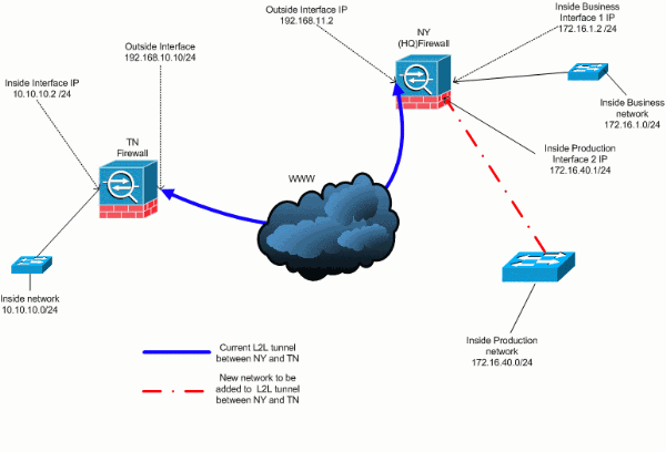
There is currently a LAN-to-LAN (L2L) VPN tunnel that is between the NY and TN office. The NY office just added a new network to be used by the CSI development group. This group requires access to resources that reside in the TN office. The task at hand is to add the new network to the already existing VPN tunnel.
Configure
In this section, you are presented with the information to configure the features described in this document.
Note: Use the Command Lookup Tool (registered customers only) to obtain more information on the commands used in this section.
Network Diagram
This document uses this network setup:

Adding Network to the IPSec Tunnel
This document uses this configuration:
| NY (HQ) Firewall Config |
|---|
ASA-NY-HQ#show running-config : Saved : ASA Version 7.2(2) ! hostname ASA-NY-HQ domain-name corp2.com enable password WwXYvtKrnjXqGbu1 encrypted names ! interface Ethernet0/0 nameif outside security-level 0 ip address 192.168.11.2 255.255.255.0 ! interface Ethernet0/1 nameif inside security-level 100 ip address 172.16.1.2 255.255.255.0 ! interface Ethernet0/2 nameif Cisco security-level 70 ip address 172.16.40.2 255.255.255.0 ! interface Ethernet0/3 shutdown no nameif no security-level no ip address ! interface Management0/0 shutdown no nameif no security-level no ip address ! passwd 2KFQnbNIdI.2KYOU encrypted ftp mode passive dns server-group DefaultDNS domain-name corp2.com access-list inside_nat0_outbound extended permit ip 172.16.1.0 255.255.255.0 10.10.10.0 255.255.255.0 !--- You must be sure that you configure the !--- opposite of these access control lists !--- on the other end of the VPN tunnel. access-list inside_nat0_outbound extended permit ip 172.16.40.0 255.255.255.0 10.10.10.0 255.255.255.0 access-list outside_20_cryptomap extended permit ip 172.16.1.0 255.255.255.0 10.10.10.0 255.255.255.0 !--- You must be sure that you configure the !--- opposite of these access control lists !--- on the other end of the VPN tunnel. access-list outside_20_cryptomap extended permit ip 172.16.40.0 255.255.255.0 10.10.10.0 255.255.255.0 !--- Output is suppressed. nat-control global (outside) 1 interface nat (inside) 0 access-list inside_nat0_outbound nat (inside) 1 172.16.1.0 255.255.255.0 !--- The new network is also required to have access to the Internet. !--- So enter an entry into the NAT statement for this new network. nat (inside) 1 172.16.40.0 255.255.255.0 route outside 0.0.0.0 0.0.0.0 192.168.11.100 1 timeout xlate 3:00:00 timeout conn 1:00:00 half-closed 0:10:00 udp 0:02:00 icmp 0:00:02 timeout sunrpc 0:10:00 h323 0:05:00 h225 1:00:00 mgcp 0:05:00 mgcp-pat 0:05:00 timeout sip 0:30:00 sip_media 0:02:00 sip-invite 0:03:00 sip-disconnect 0:02:00 timeout uauth 0:05:00 absolute no snmp-server location no snmp-server contact snmp-server enable traps snmp authentication linkup linkdown coldstart crypto ipsec transform-set ESP-3DES-SHA esp-3des esp-sha-hmac crypto map outside_map 20 match address outside_20_cryptomap crypto map outside_map 20 set peer 192.168.10.10 crypto map outside_map 20 set transform-set ESP-3DES-SHA crypto map outside_map interface outside crypto isakmp enable outside crypto isakmp policy 10 authentication pre-share encryption 3des hash sha group 2 lifetime 86400 crypto isakmp nat-traversal 20 tunnel-group 192.168.10.10 type ipsec-l2l tunnel-group 192.168.10.10 ipsec-attributes pre-shared-key * !--- Output is suppressed. : end ASA-NY-HQ# |
Removing Network from IPSec Tunnel
Use this steps to remove the network from the IPSec Tunnel configuation.Here, consider that the network 172.16.40.0/24 has been removed from the NY (HQ) Secuirty Appliance configuration.
-
Before remove the network from the tunnel, tear down the IPSec connection, which also clears the security associations related to phase 2.
ASA-NY-HQ# clear crypto ipsec sa
Clears the security associations related to phase 1 as follows
ASA-NY-HQ# clear crypto isakmp sa
-
Remove the interesting traffic ACL for the IPSec tunnel.
ASA-NY-HQ(config)# no access-list outside_20_cryptomap extended permit ip 172.16.40.0
 255.255.255.0 10.10.10.0 255.255.255.0
-
Remove the ACL (inside_nat0_outbound), since the traffic is excluded from the nat.
ASA-NY-HQ(config)# no access-list inside_nat0_outbound extended permit ip 172.16.40.0
 255.255.255.0 10.10.10.0 255.255.255.0
-
Clear the NAT translation as shown
ASA-NY-HQ# clear xlate
-
When ever you modify the tunnel configuration, remove and reapply this crypto commands to take the latest configuration in the outside interface
ASA-NY-HQ(config)# crypto map outside_map interface outside
ASA-NY-HQ(config)# crypto isakmp enable outside
-
Save active configuration to the flash "write memory".
-
Follow the same procedure for the other end - TN Security appliance to remove the configurations.
-
Initate the IPSec tunnel and verify the connection.
Verify
Use this section to confirm that your configuration works properly.
The Output Interpreter Tool (registered customers only) (OIT) supports certain show commands. Use the OIT to view an analysis of show command output.
-
ping inside 172.16.40.20

-
show crypto isakmp sa

-
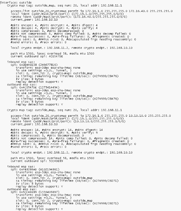
show crypto ipsec sa

Troubleshoot
Refer to these documents for more troubleshooting information:
Related Information
Revision History
| Revision | Publish Date | Comments |
|---|---|---|
1.0 |
09-Apr-2007 |
Initial Release |
Contact Cisco
- Open a Support Case

- (Requires a Cisco Service Contract)


 Feedback