Introduction
This document describes deploying dual ISP setup using Virtual Tunnel Interfaces on a FTDdevice managed by FMC.
Prerequisites
Basic Requirements
- A foundational understanding of Site-to-Site VPNs would be beneficial. This background assists in grasping the VTI setup process, including the key concepts and configurations involved.
- Understanding the fundamentals of configuring and managing VTIs on the Cisco Firepower platform is essential. This includes knowledge of how VTIs function within the FTD and how they are controlled via the FMC interface.
Components Used
- Cisco Firepower Threat Defense (FTD) for VMware: Version 7.0.0
- Firepower Management Center (FMC): Version 7.2.4 (build 169)
The information in this document was created from the devices in a specific lab environment. All of the devices used in this document started with a cleared (default) configuration. If your network is live, ensure that you understand the potential impact of any command.
Configurations on FMC
Topology Configuration
- Navigate to Devices >VPN > Site To Site.
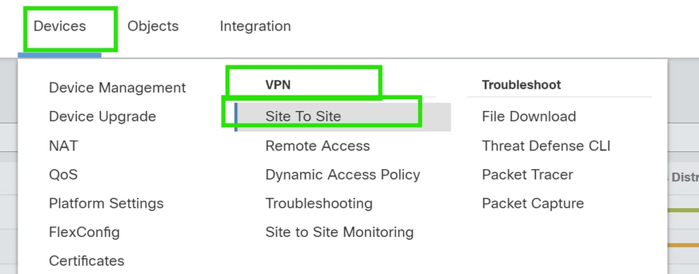
2. Click Add to add VPN topology.

3. Give a name for the topology, choose VTI and Point-to-Point, and select an IKE version (IKEv2 in this case).

Endpoint Configuration
1. Choose the device on which the tunnel needs to be configured.
Add the remote peer details.
You can either add a new Virtual Template Interface by clicking on the "+" icon or select one from the existing list.
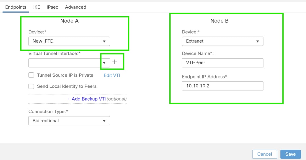
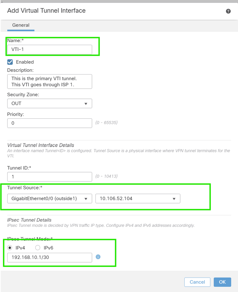
If you are creating a new VTI interface, then add the correct parameters, enable it, and click "OK".
NOTE: This becomes the primary VTI.
3. Click on "+ ". Add Backup VIT" to add a secondary VIT.
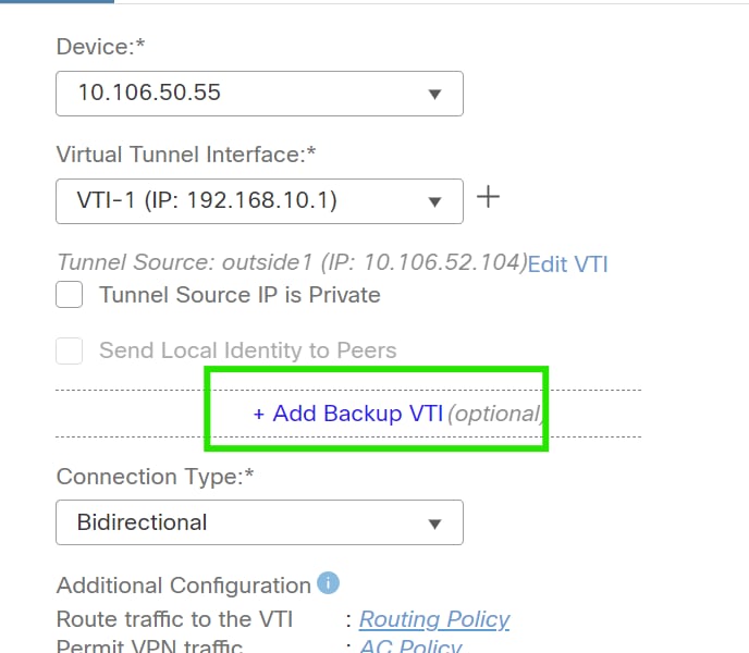
4. Click on "+" to add parameter for secondary VTI (if not already configured).
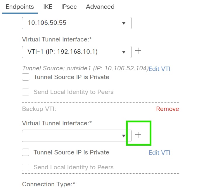
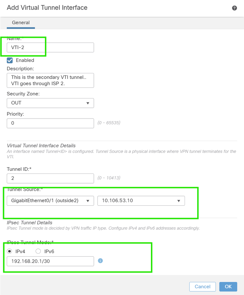
5. If you are creating a new VTI interface, then add the correct parameters, enable it, and click "OK".
NOTE: This becomes the secondary VTI.
IKE configuration
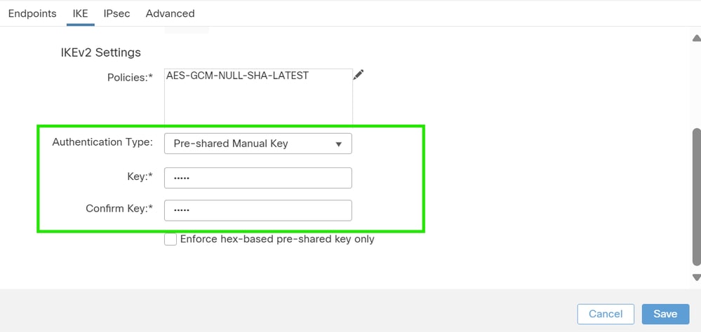
1. Navigate to the IKE tab. You can choose to use a predefined policy else click the pencil button next to the Policy tab to create a new one or select another available policy based on your requirement.
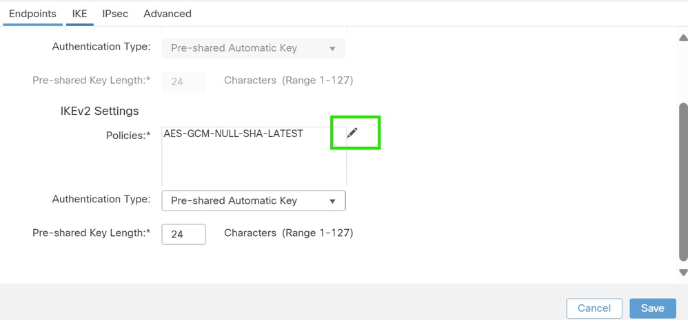
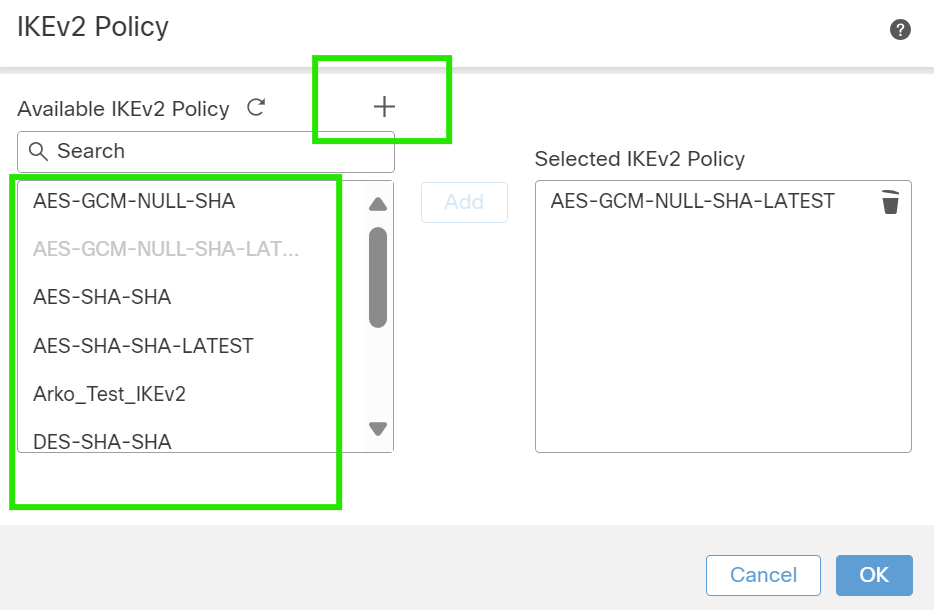
2. Select the Authentication Type. If a pre-shared manual key is used, provide the key in the Key and Confirm Key boxes.
IPsec configuration
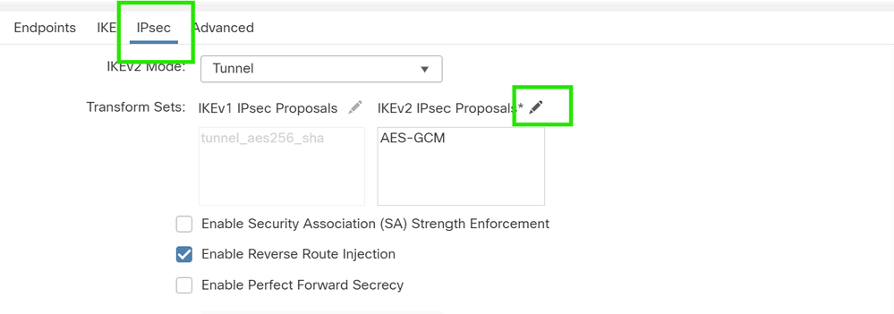
Navigate to the IPsec tab. You can choose to use a predefined proposal by clicking the pencil button next to the proposal tab to create a new one or select another available proposal based on your requirement.
Routing Configuration
1. Go to Device > Device Management and click on the pencil icon to edit the device (FTD).

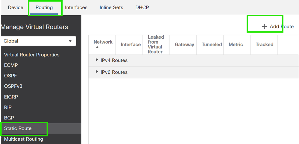
2. Go to Routing > Static Route and click on the "+" button to add a route to the primary and secondary VTI.
NOTE: You can configure the appropriate routing method for your traffic to pass through the tunnel interface. In this case, static routes have been used.
3. Add two routes for your protected network and set a higher AD value (in this case 2) for the secondary route.
The first route uses the VTI-1 interface, and the second uses the VTI-2 interface.

Verify
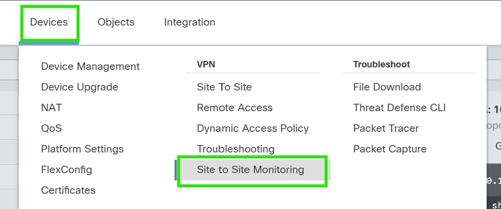
1. Go to Devices > VPN > Site to Site Monitoring .
2. Click on the eye to check more details about the status of the tunnel.


 Feedback