Configure and Verify Secure Firewall and Firepower Internal Switch Captures
Available Languages
Download Options
Bias-Free Language
The documentation set for this product strives to use bias-free language. For the purposes of this documentation set, bias-free is defined as language that does not imply discrimination based on age, disability, gender, racial identity, ethnic identity, sexual orientation, socioeconomic status, and intersectionality. Exceptions may be present in the documentation due to language that is hardcoded in the user interfaces of the product software, language used based on RFP documentation, or language that is used by a referenced third-party product. Learn more about how Cisco is using Inclusive Language.
Contents
Introduction
This document describes the configuration and verification of the Firepower, and the Secure Firewall internal switch captures.
Prerequisites
Requirements
Basic product knowledge, capture analysis.
Components Used
The information in this document was created from the devices in a specific lab environment. All of the devices used in this document started with a cleared (default) configuration. If your network is live, ensure that you understand the potential impact of any command.
The information in this document is based on these software and hardware versions:
- Secure Firewall 31xx, 42xx
- Firepower 41xx
- Firepower 93xx
- Cisco Secure eXtensible Operating System (FXOS) 2.12.0.x
- Cisco Secure Firewall Threat Defense (FTD) 7.2.0.x, 7.4.1-172
- Cisco Secure Firewall Management Center (FMC) 7.2.0.x, 7.4.1-172
- Adaptive Security Appliance (ASA) 9.18(1)x, 9.20(x)
- Wireshark 3.6.7 (https://www.wireshark.org/download.html)
Background Information
High-Level Overview of the System Architecture
From the packet flow perspective, the architecture of the Firepower 4100/9300 and Secure Firewall 3100/4200 can be visualized as shown in this figure:
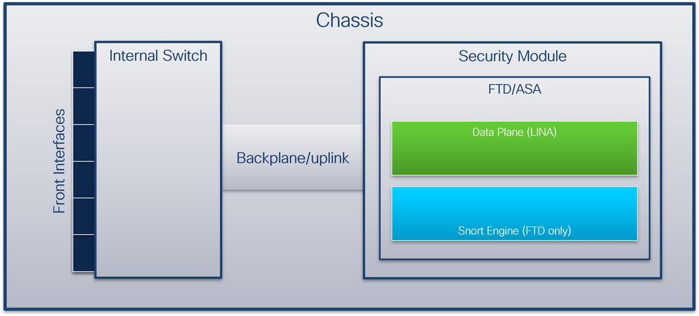
The chassis includes these components:
- Internal switch – forwards packet from the network to the application and vice versa. The internal switch is connected to the front interfaces that reside on the built-in interface module or external network modules and connect to external devices, for example, switches. Examples of front interfaces are Ethernet 1/1, Ethernet 2/4, and so on. The “front” is not a strong technical definition. In this document, it is used to distinguish interfaces connected to external devices from the backplane or uplink interfaces.
- Backplane or uplink – an internal interface that connects the security module (SM) to the internal switch.
- Management uplink – an internal interface exclusive to Secure Firewall 3100/4200 that provides management traffic path between the internal switch and the application.
- Management interface - a physical interface on the chassis.
- Data interfaces - interfaces allocated to the application used to forward traffic.
In the case of the Secure Firewall 3100/4200, the data, management and the uplink interfaces are mapped to specific internal switch ports.
The mapping can be verified in the output of the FXOS local-mgmt command shell show portmanager switch status command output.
In this example, port 0/18 is the backplane/uplink interface, and port 0/19 is the management uplink interface.
firepower-3140# connect local-mgmt
Warning: network service is not available when entering 'connect local-mgmt'
firepower-3140(local-mgmt)# show portmanager switch status
Dev/Port     Mode    Link   Speed  Duplex    Loopback      Autoneg      FEC        Link Scan   Port Manager
---------  --------  -----  -----  ------  -------------  ---------  ----------   -----------  ------------
0/1          SGMII    Up     1G     Full        None        No         None          None       Link-Up
0/2          SGMII    Up     1G     Full        None        No         None          None       Link-Up
0/3          SGMII   Down    1G     Full         n/a        No         None          None      Force-Link-Down
0/4          SGMII   Down    1G     Full         n/a        No         None          None      Force-Link-Down
0/5          SGMII   Down    1G     Full         n/a        No         None          None      Force-Link-Down
0/6          SGMII   Down    1G     Full         n/a        No         None          None      Force-Link-Down
0/7          SGMII   Down    1G     Full         n/a        No         None          None      Force-Link-Down
0/8          SGMII   Down    1G     Full         n/a        No         None          None      Force-Link-Down
0/9          SR_LR   Down    25G    Full         n/a        No         None          None      Force-Link-Down
0/10         SR_LR   Down    25G    Full         n/a        No         None          None      Force-Link-Down
0/11       1000_BaseXDown    1G     Full         n/a        No         None          None      Force-Link-Down
0/12       1000_BaseXDown    1G     Full         n/a        No         None          None      Force-Link-Down
0/13       1000_BaseXDown    1G     Full         n/a        No         None          None      Force-Link-Down
0/14       1000_BaseXDown    1G     Full         n/a        No         None          None      Force-Link-Down
0/15       1000_BaseXDown    1G     Full         n/a        No         None          None      Force-Link-Down
0/16       1000_BaseXDown    1G     Full         n/a        No         None          None      Force-Link-Down
0/17       1000_BaseX Up     1G     Full        None        No         None          None       Link-Up
0/18          KR2     Up     50G    Full        None        No         None          None       Link-Up
0/19          KR      Up     25G    Full        None        No         None          None       Link-Up
0/20          KR      Up     25G    Full        None        No         None          None       Link-Up
This table shows backplane interfaces on Firepower 4100/9300 and uplink interfaces on Secure Firewall 3100/4200:
|
Platform |
Number of supported security modules |
Backplane/uplink interfaces |
Management uplink interfaces |
Mapped internal switch port |
Mapped application interfaces |
|
Firepower 4100 (except Firepower 4110/4112) |
1 |
SM1: Ethernet1/9 Ethernet1/10 |
N/A |
N/A |
Internal-Data0/0 Internal-Data0/1 |
|
Firepower 4110/4112 |
1 |
Ethernet1/9 |
N/A |
N/A |
Internal-Data0/0 Internal-Data0/1 |
|
Firepower 9300 |
3 |
SM1: Ethernet1/9 Ethernet1/10 SM2: Ethernet1/11 Ethernet1/12 SM3: Ethernet1/13 Ethernet1/14 |
N/A |
N/A |
Internal-Data0/0 Internal-Data0/1
Internal-Data0/1
Internal-Data0/1 |
|
Secure Firewall 3100 |
1 |
SM1: in_data_uplink1 |
in_mgmt_uplink1 |
Port 0/18 Port 0/19 |
Internal-Data0/1 Management1/1 |
|
Secure Firewall 4200 |
1 |
SM1: in_data_uplink1 SM1: in_data_uplink2 (only 4245) |
in_mgmt_uplink1 in_mgmt_uplink2 |
Port 0/11 Port 0/12 (only 4245) Port 0/13 Port 0/14 |
Internal-Data0/1 Internal-Data0/2 (only 4245) Management1/1 Management1/2 |
In the case Firepower 4100/9300 with 2 backplane interfaces per module or Secure Firewall 4245 with 2 data uplink interfaces, the internal switch and the applications on the modules perform traffic load-balancing over the 2 interfaces.
- Security module, security engine, or blade – the module where applications such as FTD or ASA are installed. Firepower 9300 supports up to 3 security modules.
- Mapped application interface - the names of the backplane or uplink interfaces in applications, such as FTD or ASA.
Use the show interface detail command to verify internal interfaces:
> show interface detail | grep Interface
Interface Internal-Control0/0 "ha_ctl_nlp_int_tap", is up, line protocol is up
  Control Point Interface States:
        Interface number is 6
        Interface config status is active
        Interface state is active
Interface Internal-Data0/0 "", is up, line protocol is up
  Control Point Interface States:
        Interface number is 2
        Interface config status is active
        Interface state is active
Interface Internal-Data0/1 "", is up, line protocol is up
  Control Point Interface States:
        Interface number is 3
        Interface config status is active
        Interface state is active
Interface Internal-Data0/2 "nlp_int_tap", is up, line protocol is up
  Control Point Interface States:
        Interface number is 4
        Interface config status is active
        Interface state is active
Interface Internal-Data0/3 "ccl_ha_nlp_int_tap", is up, line protocol is up
  Control Point Interface States:
        Interface number is 5
        Interface config status is active
        Interface state is active
Interface Internal-Data0/4 "cmi_mgmt_int_tap", is up, line protocol is up
  Control Point Interface States:
        Interface number is 7
        Interface config status is active
        Interface state is active
Interface Port-channel6.666 "", is up, line protocol is up
Interface Ethernet1/1 "diagnostic", is up, line protocol is up
  Control Point Interface States:
        Interface number is 8
        Interface config status is active
        Interface state is active
High-Level Overview of the Internal Switch Operations
Firepower 4100/9300
To make a forwarding decision the internal switch uses an interface VLAN tag, or port VLAN tag, and a virtual network tag (VN-tag).
The port VLAN tag is used by the internal switch to identify an interface. The switch inserts the port VLAN tag into each ingress packet that came on front interfaces. The VLAN tag is automatically configured by the system and cannot be manually changed. The tag value can be checked in the fxos command shell:
firepower# connect fxos
…
firepower(fxos)# show run int e1/2
!Command: show running-config interface Ethernet1/2
!Time: Tue Jul 12 22:32:11 2022

version 5.0(3)N2(4.120)

interface Ethernet1/2
  description U: Uplink
  no lldp transmit
  no lldp receive
  no cdp enable
  switchport mode dot1q-tunnel
  switchport trunk native vlan 102
  speed 1000
  duplex full
  udld disable
  no shutdown
The VN-tag is also inserted by the internal switch and used to forward the packets to the application. It is automatically configured by the system and cannot be manually changed.
The port VLAN tag and the VN-tag are shared with the application. The application inserts the respective egress interface VLAN tags and the VN-tags into each packet. When a packet from the application is received by the internal switch on the backplane interfaces, the switch reads the egress interface VLAN tag and the VN-tag, identifies the application and the egress interface, strips the port VLAN tag and the VN-tag, and forwards the packet to the network.
Secure Firewall 3100/4200
Like in Firepower 4100/9300, the port VLAN tag is used by the internal switch to identify an interface.
The port VLAN tag is shared with the application. The application inserts the respective egress interface VLAN tags into each packet. When a packet from the application is received by the internal switch on the uplink interface, the switch reads the egress interface VLAN tag, identifies the egress interface, strips the port VLAN tag, and forwards the packet to the network.
Packet Flow and Capture Points
Firepower 4100/9300 and Secure Firewall 3100
The Firepower 4100/9300 and the Secure Firewall 3100 firewalls support packet captures on the interfaces of the internal switch.
This figure shows the packet capture points along the packet path within the chassis and the application:
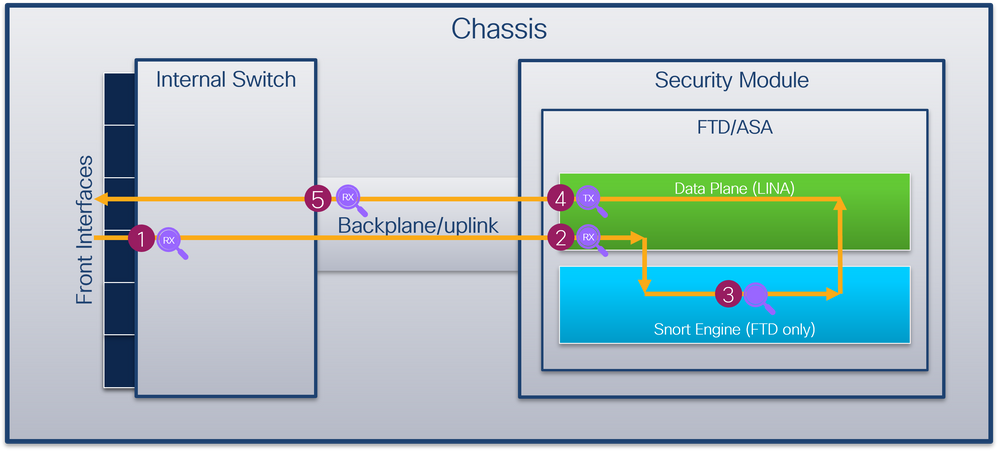
The capture points are:
- Internal switch front interface ingress capture point. A front interface is any interface connected to the peer devices such as switches.
- Data plane interface ingress capture point
- Snort capture point
- Data plane interface egress capture point
- Internal switch backplane or uplink ingress capture point. A backplane or uplink interface connects the internal switch to the application.
The internal switch supports only ingress interface captures. That is only the packets received from the network or from the ASA/FTD application can be captured. Egress packet captures are not supported.
Secure Firewall 4200
The Secure Firewall 4200 firewalls support packet captures on the interfaces of the internal switch. This figure shows the packet capture points along the packet path within the chassis and the application:
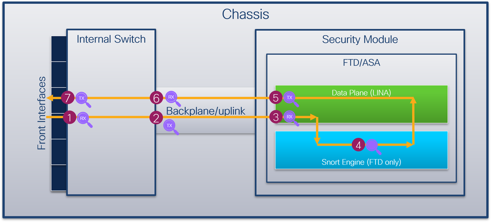
The capture points are:
- Internal switch front interface ingress capture point. A front interface is any interface connected to the peer devices such as switches.
- Internal switch backplane interface egress capture point.
- Data plane interface ingress capture point
- Snort capture point
- Data plane interface egress capture point
- Internal switch backplane or uplink ingress capture point. A backplane or uplink interface connects the internal switch to the application.
- Internal switch front interface egress capture point.
The internal switch optionally supports bidirectional - both ingress and egress - captures. By default, the internal switch captures packets in the ingress direction.
Configuration and Verification on Firepower 4100/9300
The Firepower 4100/9300 internal switch captures can be configured in Tools > Packet Capture on FCM or in scope packet-capture in FXOS CLI. For the description of the packet capture options refer to the Cisco Firepower 4100/9300 FXOS Chassis Manager Configuration Guide or Cisco Firepower 4100/9300 FXOS CLI Configuration Guide, chapter Troubleshooting, section Packet Capture.
These scenarios cover common use cases of Firepower 4100/9300 internal switch captures.
Packet Capture on a Physical or Port-channel Interface
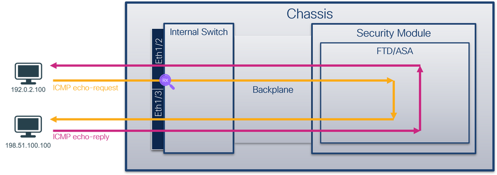
Use the FCM and CLI to configure and verify a packet capture on interface Ethernet1/2 or Portchannel1 interface. In the case of a port-channel interface, ensure to select all physical member interfaces.
Topology, packet flow, and the capture points
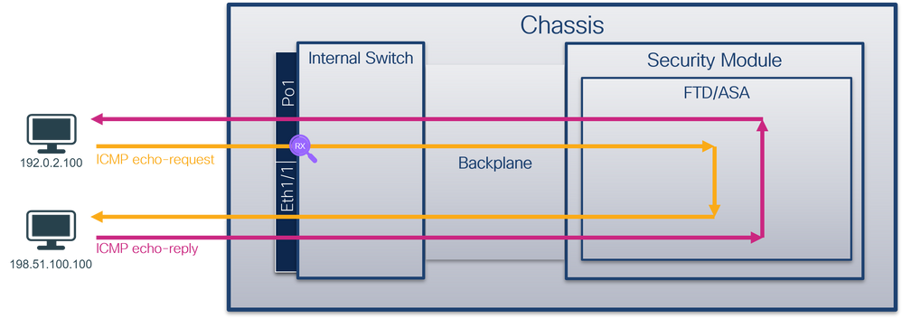
Configuration
FCM
Perform these steps on FCM to configure a packet capture on interfaces Ethernet1/2 or Portchannel1:
- Use Tools > Packet Capture > Capture Session to create a new capture session:

- Select the interface Ethernet1/2, provide the session name and click Save and Run to activate the capture:
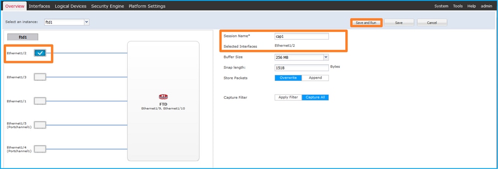
- In the case of a port-channel interface, select all physical member interfaces, provide the session name and click Save and Run to activate the capture:
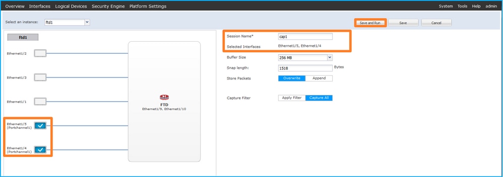
FXOS CLI
Perform these steps on FXOS CLI to configure a packet capture on interfaces Ethernet1/2 or Portchannel1:
- Identify the application type and identifier:
firepower# scope ssa
firepower /ssa # show app-instance
App Name   Identifier Slot ID    Admin State Oper State       Running Version Startup Version Deploy Type Turbo Mode Profile Name Cluster State   Cluster Role
---------- ---------- ---------- ----------- ---------------- --------------- --------------- ----------- ---------- ------------ --------------- ------------
ftd        ftd1       1          Enabled     Online           7.2.0.82        7.2.0.82        Native      No                      Not Applicable  None
- In the case of a port-channel interface, identify its member interfaces:
firepower# connect fxos
<output skipped>
firepower(fxos)# show port-channel summary
Flags:  D - Down        P - Up in port-channel (members)
        I - Individual  H - Hot-standby (LACP only)
        s - Suspended   r - Module-removed
        S - Switched    R - Routed
        U - Up (port-channel)
        M - Not in use. Min-links not met
--------------------------------------------------------------------------------
Group Port-       Type     Protocol  Member Ports
      Channel
--------------------------------------------------------------------------------
1     Po1(SU)     Eth      LACP      Eth1/4(P)    Eth1/5(P)
- Create a capture session:
firepower# scope packet-capture
firepower /packet-capture # create session cap1
firepower /packet-capture/session* # create phy-port Eth1/2
firepower /packet-capture/session/phy-port* # set app ftd
firepower /packet-capture/session/phy-port* # set app-identifier ftd1
firepower /packet-capture/session/phy-port* # up
firepower /packet-capture/session* # enable
firepower /packet-capture/session* # commit
firepower /packet-capture/session #
For port-channel interfaces, a separate capture for each member interface is configured:
firepower# scope packet-capture
firepower /packet-capture # create session cap1
firepower /packet-capture/session* # create phy-port Eth1/4
firepower /packet-capture/session/phy-port* # set app ftd
firepower /packet-capture/session/phy-port* # set app-identifier ftd1
firepower /packet-capture/session/phy-port* # up
firepower /packet-capture/session* # create phy-port Eth1/5
firepower /packet-capture/session/phy-port* # set app ftd
firepower /packet-capture/session/phy-port* # set app-identifier ftd1
firepower /packet-capture/session/phy-port* # up
firepower /packet-capture/session* # enable
firepower /packet-capture/session* # commit
firepower /packet-capture/session #
Verification
FCM
Verify the Interface Name, ensure that the Operational Status is up and that the File Size (in bytes) increases:

Portchannel1 with member interfaces Ethernet1/4 and Ethernet1/5:

FXOS CLI
Verify the capture details in scope packet-capture:
firepower# scope packet-capture
firepower /packet-capture # show session cap1

Traffic Monitoring Session:
    Packet Capture Session Name: cap1
    Session: 1
    Admin State: Enabled
    Oper State: Up
    Oper State Reason: Active
    Config Success: Yes
    Config Fail Reason:
    Append Flag: Overwrite
    Session Mem Usage: 256  MB
    Session Pcap Snap Len: 1518  Bytes
    Error Code: 0
    Drop Count: 0

Physical ports involved in Packet Capture:
    Slot Id: 1
    Port Id: 2
    Pcapfile: /workspace/packet-capture/session-1/cap1-ethernet-1-2-0.pcap
    Pcapsize: 75136  bytes
    Filter:
    Sub Interface: 0
    Application Instance Identifier: ftd1
    Application Name: ftd
Port-channel 1 with member interfaces Ethernet1/4 and Ethernet1/5:
firepower# scope packet-capture
firepower /packet-capture # show session cap1

Traffic Monitoring Session:
    Packet Capture Session Name: cap1
    Session: 1
    Admin State: Enabled
    Oper State: Up
    Oper State Reason: Active
    Config Success: Yes
    Config Fail Reason:
    Append Flag: Overwrite
    Session Mem Usage: 256  MB
    Session Pcap Snap Len: 1518  Bytes
    Error Code: 0
    Drop Count: 0

Physical ports involved in Packet Capture:
    Slot Id: 1
    Port Id: 4
    Pcapfile: /workspace/packet-capture/session-1/cap1-ethernet-1-4-0.pcap
    Pcapsize: 310276  bytes
    Filter:
    Sub Interface: 0
    Application Instance Identifier: ftd1
    Application Name: ftd

    Slot Id: 1
    Port Id: 5
    Pcapfile: /workspace/packet-capture/session-1/cap1-ethernet-1-5-0.pcap
    Pcapsize: 160  bytes
    Filter:
    Sub Interface: 0
    Application Instance Identifier: ftd1
    Application Name: ftd
Collect capture files
Perform the steps in the section Collect Firepower 4100/9300 Internal Switch Capture Files.
Capture file analysis
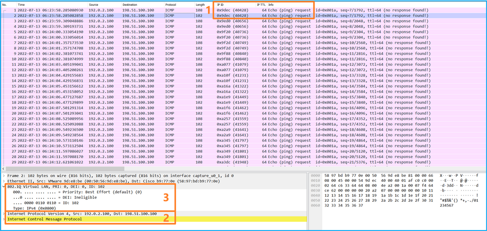
Use a packet capture file reader application to open the capture file for Ethernet1/2. Select the first packet and check the key points:
- Only ICMP echo-request packets are captured. Each packet is captured and shown 2 times.
- The original packet header is without the VLAN tag.
- The internal switch inserts additional port VLAN tag 102 that identifies the ingress interface Ethernet1/2.
- The internal switch inserts an additional VN tag.
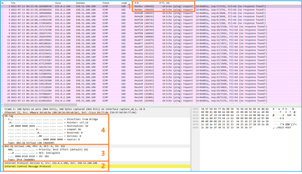
Select the second packet and check the key points:
- Only ICMP echo-request packets are captured. Each packet is captured and shown 2 times.
- The original packet header is without the VLAN tag.
- The internal switch inserts additional port VLAN tag 102 that identifies the ingress interface Ethernet1/2.
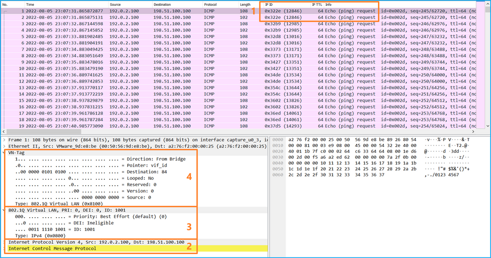
Open the capture files for Portchannel1 member interfaces. Select the first packet and check the key points:
- Only ICMP echo-request packets are captured. Each packet is captured and shown 2 times.
- The original packet header is without the VLAN tag.
- The internal switch inserts an additional port VLAN tag 1001 that identifies the ingress interface Portchannel1.
- The internal switch inserts an additional VN tag.
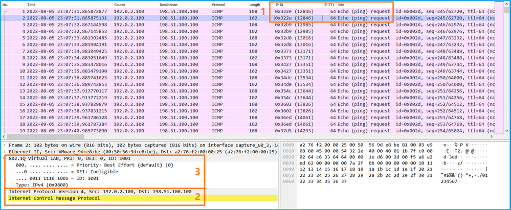
Select the second packet and check the key points:
- Only ICMP echo-request packets are captured. Each packet is captured and shown 2 times.
- The original packet header is without the VLAN tag.
- The internal switch inserts an additional port VLAN tag 1001 that identifies the ingress interface Portchannel1.
Explanation
When a packet capture on a front interface is configured, the switch simultaneously captures each packet twice:
- After the insertion of the port VLAN tag.
- After the insertion of the VN tag.
In the order of operations, the VN tag is inserted at a later stage than the port VLAN tag insertion. However, in the capture file, the packet with the VN tag is shown earlier than the packet with the port VLAN tag.
This table summarizes the task:
|
Task |
Capture point |
Internal port VLAN in captured packets |
Direction |
Captured traffic |
|
Configure and verify a packet capture on interface Ethernet1/2 |
Ethernet1/2 |
102 |
Ingress only |
ICMP echo requests from host 192.0.2.100 to host 198.51.100.100 |
|
Configure and verify a packet capture on interface Portchannel1 with member interfaces Ethernet1/4 and Ethernet1/5 |
Ethernet1/4 Ethernet1/5 |
1001 |
Ingress only |
ICMP echo requests from host 192.0.2.100 to host 198.51.100.100 |
Packet Captures on Backplane Interfaces
Use the FCM and CLI to configure and verify a packet capture on backplane interfaces.
Topology, packet flow, and the capture points
Configuration
FCM
Perform these steps on FCM to configure packet captures on backplane interfaces:
- Use Tools > Packet Capture > Capture Session to create a new capture session:

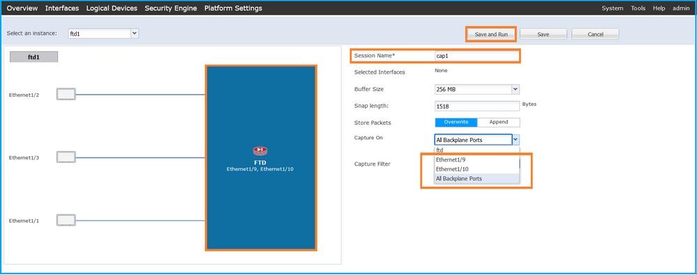
- To capture packets on all backplane interfaces, select the application, then All Backplane Ports from the Capture On the dropdown list. Alternatively, choose the specific backplane interface. In this case, backplane interfaces Ethernet1/9 and Ethernet1/10 are available. Provide the Session Name and click Save and Run to activate the capture:
FXOS CLI
Perform these steps on FXOS CLI to configure packet captures on backplane interfaces:
- Identify the application type and identifier:
firepower# scope ssa
firepower /ssa# show app-instance
App Name   Identifier Slot ID    Admin State Oper State       Running Version Startup Version Deploy Type Turbo Mode Profile Name Cluster State   Cluster Role
---------- ---------- ---------- ----------- ---------------- --------------- --------------- ----------- ---------- ------------ --------------- ------------
ftd        ftd1       1          Enabled     Online           7.2.0.82        7.2.0.82        Native      No                      Not Applicable  None
- Create a capture session:
firepower# scope packet-capture
firepower /packet-capture # create session cap1
firepower /packet-capture/session* # create phy-port Eth1/9
firepower /packet-capture/session/phy-port* # set app ftd
firepower /packet-capture/session/phy-port* # set app-identifier ftd1
firepower /packet-capture/session/phy-port* # up
firepower /packet-capture/session* #  create phy-port Eth1/10
firepower /packet-capture/session/phy-port* # set app ftd
firepower /packet-capture/session/phy-port* # set app-identifier ftd1
firepower /packet-capture/session/phy-port* # up
firepower /packet-capture/session* # enable
firepower /packet-capture/session* # commit
firepower /packet-capture/session #
Verification
FCM
Verify the Interface Name, ensure that the Operational Status is up and that the File Size (in bytes) increases:

FXOS CLI
Verify the capture details in scope packet-capture:
firepower# scope packet-capture
firepower /packet-capture #  show session cap1

Traffic Monitoring Session:
    Packet Capture Session Name: cap1
    Session: 1
    Admin State: Enabled
    Oper State: Up
    Oper State Reason: Active
    Config Success: Yes
    Config Fail Reason:
    Append Flag: Overwrite
    Session Mem Usage: 256  MB
    Session Pcap Snap Len: 1518  Bytes
    Error Code: 0
    Drop Count: 0

Physical ports involved in Packet Capture:
    Slot Id: 1
    Port Id: 10
    Pcapfile: /workspace/packet-capture/session-1/cap1-ethernet-1-10-0.pcap
    Pcapsize: 1017424  bytes
    Filter:
    Sub Interface: 0
    Application Instance Identifier: ftd1
    Application Name: ftd

    Slot Id: 1
    Port Id: 9
    Pcapfile: /workspace/packet-capture/session-1/cap1-ethernet-1-9-0.pcap
    Pcapsize: 1557432  bytes
    Filter:
    Sub Interface: 0
    Application Instance Identifier: ftd1
    Application Name: ftd
Collect capture files
Perform the steps in the section Collect Firepower 4100/9300 Internal Switch Capture Files.
Capture file analysis
Use a packet capture file reader application to open the capture files. In the case of more than 1 backplane interface, ensure to open all capture files for each backplane interface. In this case, the packets are captured on the backplane interface Ethernet1/9.
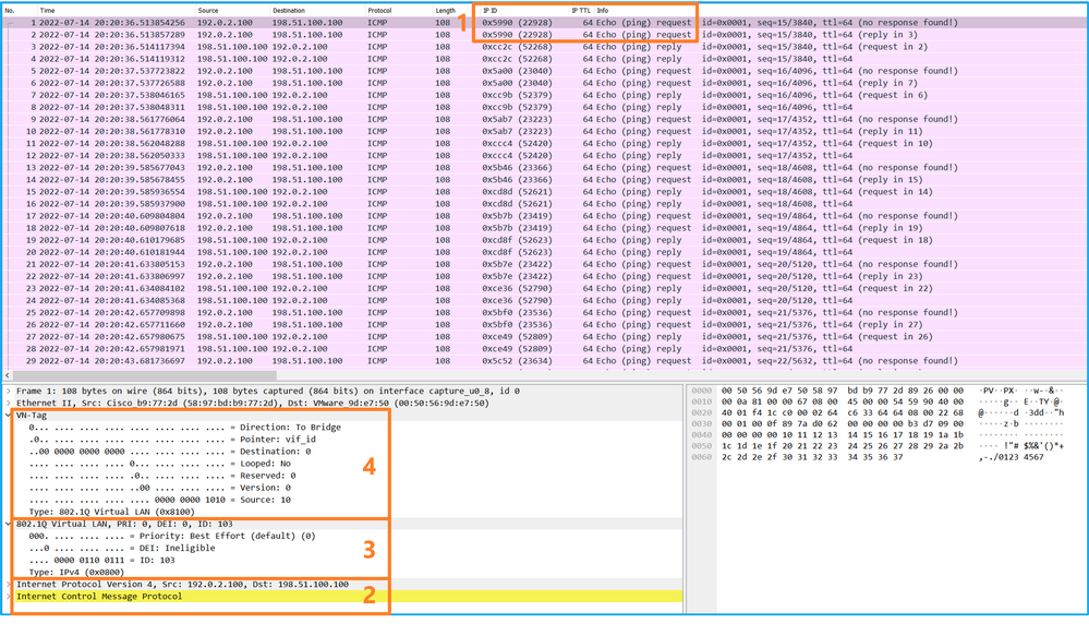
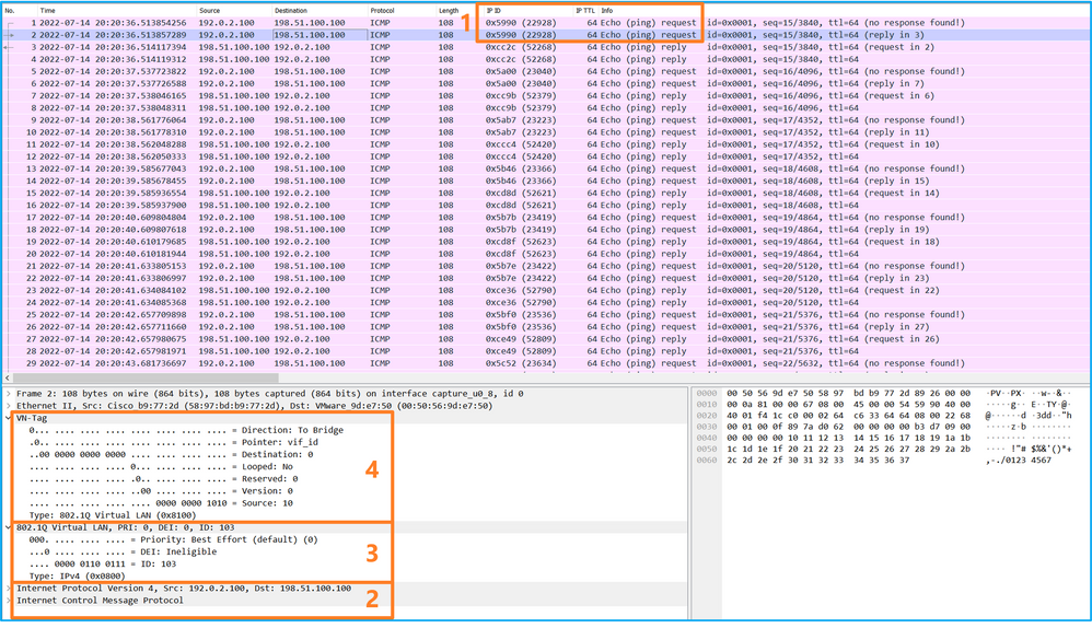
Select the first and the second packets, and check the key points:
- Each ICMP echo request packet is captured and shown 2 times.
- The original packet header is without the VLAN tag.
- The internal switch inserts additional port VLAN tag 103 that identifies the egress interface Ethernet1/3.
- The internal switch inserts an additional VN tag.
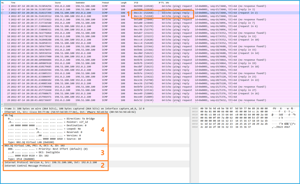
Select the third and the fourth packets, and check the key points:
- Each ICMP echo reply is captured and shown 2 times.
- The original packet header is without the VLAN tag.
- The internal switch inserts additional port VLAN tag 102 that identifies the egress interface Ethernet1/2.
- The internal switch inserts an additional VN tag.
Explanation
When a packet capture on a backplane interface is configured, the switch simultaneously captures each packet twice. In this case, the internal switch receives packets that are already tagged by the application on the security module with the port VLAN tag and the VN tag. The VLAN tag identifies the egress interface that the internal chassis uses to forward the packets to the network. The VLAN tag 103 in ICMP echo request packets identifies Ethernet1/3 as the egress interface, while VLAN tag 102 in ICMP echo reply packets identifies Ethernet1/2 as the egress interface. The internal switch removes the VN tag and the internal interface VLAN tag before the packets are forwarded to the network.
This table summarizes the task:
|
Task |
Capture point |
Internal port VLAN in captured packets |
Direction |
Captured traffic |
|
Configure and verify packet captures on backplane interfaces |
Backplane interfaces |
102 103 |
Ingress only |
ICMP echo requests from host 192.0.2.100 to host 198.51.100.100 ICMP echo replies from host 198.51.100.100 to host 192.0.2.100 |
Packet Captures on Application and Application Ports
Application or application port packet captures are always configured on backplane interfaces and additionally on the front interfaces if the user specifies the application capture direction.
There are mainly 2 use cases:
- Configure packet captures on backplane interfaces for packets that leave a specific front interface. For example, configure packet captures on the backplane interface Ethernet1/9 for packets that leave interface Ethernet1/2.
- Configure simultaneous packet captures on a specific front interface and the backplane interfaces. For example, configure simultaneous packet captures on interface Ethernet1/2 and on the backplane interface Ethernet1/9 for packets that leave interface Ethernet1/2.
This section covers both use cases.
Task 1
Use the FCM and CLI to configure and verify a packet capture on the backplane interface. Packets for which the application port Ethernet1/2 is identified as the egress interface are captured. In this case, ICMP replies are captured.
Topology, packet flow, and the capture points
Configuration
FCM
Perform these steps on FCM to configure a packet capture on the FTD application and the application port Ethernet1/2:
- Use Tools > Packet Capture > Capture Session to create a new capture session:

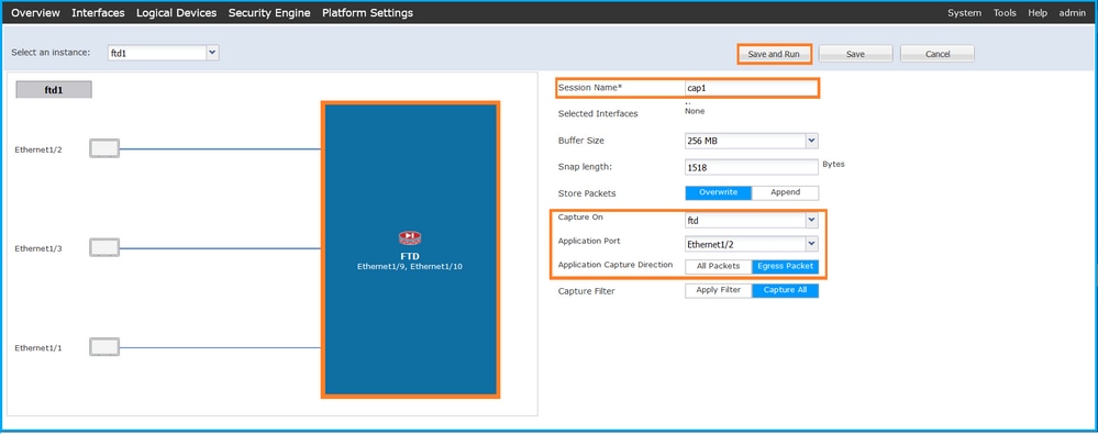
- Select the application, Ethernet1/2 in the Application Port dropdown list and select Egress Packet in the Application Capture Direction. Provide the Session Name and click Save and Run to activate the capture:
FXOS CLI
Perform these steps on FXOS CLI to configure packet captures on backplane interfaces:
- Identify the application type and identifier:
firepower# scope ssa
firepower /ssa#  show app-instance
App Name   Identifier Slot ID    Admin State Oper State       Running Version Startup Version Deploy Type Turbo Mode Profile Name Cluster State   Cluster Role
---------- ---------- ---------- ----------- ---------------- --------------- --------------- ----------- ---------- ------------ --------------- ------------
ftd        ftd1       1          Enabled     Online           7.2.0.82        7.2.0.82        Native      No                      Not Applicable  None
- Create a capture session:
firepower# scope packet-capture
firepower /packet-capture # create session cap1
firepower /packet-capture/session* # create app-port 1 l12 Ethernet1/2 ftd
firepower /packet-capture/session/app-port* # set app-identifier ftd1
firepower /packet-capture/session/app-port* # set filter ""
firepower /packet-capture/session/app-port* # set subinterface 0
firepower /packet-capture/session/app-port* # up
firepower /packet-capture/session* # commit
firepower /packet-capture/session #
Verification
FCM
Verify the Interface Name, ensure that the Operational Status is up and that the File Size (in bytes) increases:

FXOS CLI
Verify the capture details in scope packet-capture:
firepower# scope packet-capture
firepower /packet-capture #  show session cap1

Traffic Monitoring Session:
    Packet Capture Session Name: cap1
    Session: 1
    Admin State: Enabled
    Oper State: Up
    Oper State Reason: Active
    Config Success: Yes
    Config Fail Reason:
    Append Flag: Overwrite
    Session Mem Usage: 256  MB
    Session Pcap Snap Len: 1518  Bytes
    Error Code: 0
    Drop Count: 0

Application ports involved in Packet Capture:
    Slot Id: 1
    Link Name: l12
    Port Name: Ethernet1/2
    App Name: ftd
    Sub Interface: 0
    Application Instance Identifier: ftd1

Application ports resolved to:
    Name: vnic1
    Eq Slot Id: 1
    Eq Port Id: 9
    Pcapfile: /workspace/packet-capture/session-1/cap1-vethernet-1036.pcap
    Pcapsize: 53640  bytes
    Vlan: 102
    Filter:

    Name: vnic2
    Eq Slot Id: 1
    Eq Port Id: 10
    Pcapfile: /workspace/packet-capture/session-1/cap1-vethernet-1175.pcap
    Pcapsize: 1824  bytes
    Vlan: 102
    Filter:
Collect capture files
Perform the steps in the section Collect Firepower 4100/9300 Internal Switch Capture Files.
Capture file analysis
Use a packet capture file reader application to open the capture files. In the case of multiple backplane interfaces, ensure to open all capture files for each backplane interface. In this case, the packets are captured on the backplane interface Ethernet1/9.
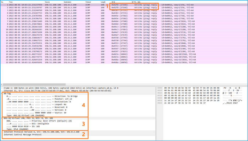
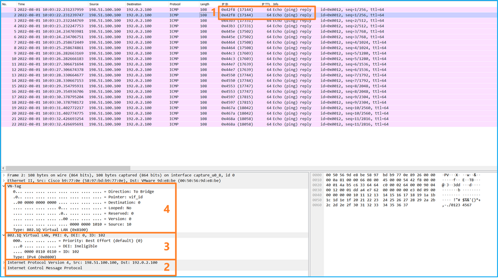
Select the first and the second packets, and check the key points:
- Each ICMP echo reply is captured and shown 2 times.
- The original packet header is without the VLAN tag.
- The internal switch inserts additional port VLAN tag 102 that identifies the egress interface Ethernet1/2.
- The internal switch inserts an additional VN tag.
Explanation
In this case, Ethernet1/2 with port VLAN tag 102 is the egress interface for the ICMP echo reply packets.
When the application capture direction is set to Egress in the capture options, packets with the port VLAN tag 102 in the Ethernet header are captured on the backplane interfaces in the ingress direction.
This table summarizes the task:
|
Task |
Capture point |
Internal port VLAN in captured packets |
Direction |
Captured traffic |
|
Configure and verify captures on application and application port Ethernet1/2 |
Backplane interfaces |
102 |
Ingress only |
ICMP echo replies from host 198.51.100.100 to host 192.0.2.100 |
Task 2
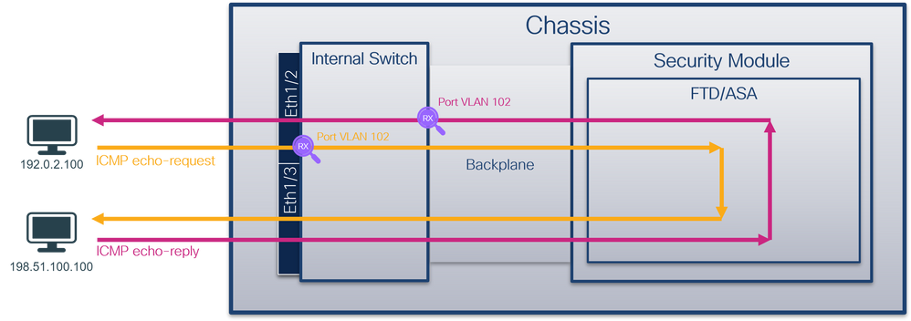
Use the FCM and CLI to configure and verify a packet capture on the backplane interface and the front interface Ethernet1/2.
Simultaneous packet captures are configured on:
- Front interface – the packets with the port VLAN 102 on the interface Ethernet1/2 are captured. Captured packets are ICMP echo requests.
- Backplane interfaces – packets for which Ethernet1/2 is identified as the egress interface, or the packets with the port VLAN 102, are captured. Captured packets are ICMP echo replies.
Topology, packet flow, and the capture points
Configuration
FCM
Perform these steps on FCM to configure a packet capture on the FTD application and the application port Ethernet1/2:
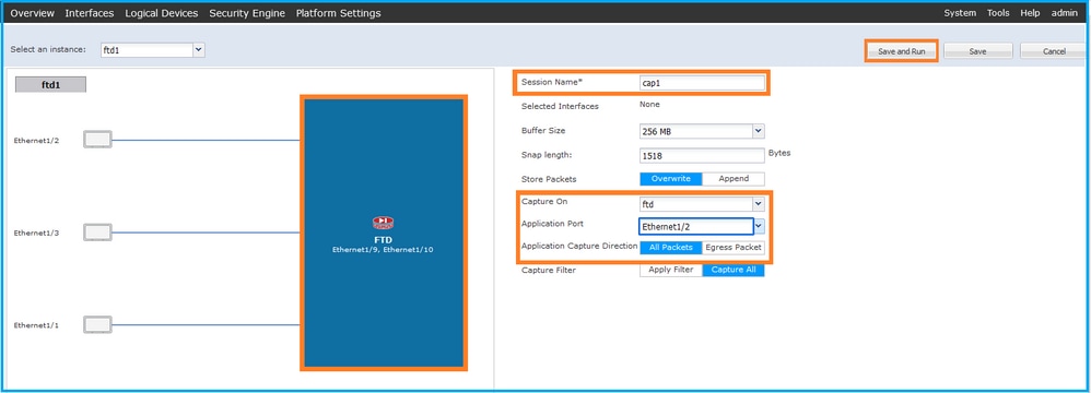
- Use Tools > Packet Capture > Capture Session to create a new capture session:

- Select the FTD application, Ethernet1/2 in the Application Port dropdown list and select All Packets in the Application Capture Direction. Provide the Session Name and click Save and Run to activate the capture:
FXOS CLI
Perform these steps on FXOS CLI to configure packet captures on backplane interfaces:
- Identify the application type and identifier:
firepower# scope ssa
firepower /ssa#  show app-instance
App Name   Identifier Slot ID    Admin State Oper State       Running Version Startup Version Deploy Type Turbo Mode Profile Name Cluster State   Cluster Role
---------- ---------- ---------- ----------- ---------------- --------------- --------------- ----------- ---------- ------------ --------------- ------------
ftd        ftd1       1          Enabled     Online           7.2.0.82        7.2.0.82        Native      No                      Not Applicable  None
- Create a capture session:
firepower# scope packet-capture
firepower /packet-capture # create session cap1
firepower /packet-capture/session* # create phy-port eth1/2
firepower /packet-capture/session/phy-port* # set app-identifier ftd1
firepower /packet-capture/session/phy-port* # exit
firepower /packet-capture/session* # create app-port 1 link12 Ethernet1/2 ftd
firepower /packet-capture/session/app-port* # set app-identifier ftd1
firepower /packet-capture/session* # enable
firepower /packet-capture/session* # commit
firepower /packet-capture/session # commit
Verification
FCM
Verify the Interface Name, ensure that the Operational Status is up and that the File Size (in bytes) increases:

FXOS CLI
Verify the capture details in scope packet-capture:
firepower# scope packet-capture
firepower /packet-capture #  show session cap1

Traffic Monitoring Session:
    Packet Capture Session Name: cap1
    Session: 1
    Admin State: Enabled
    Oper State: Up
    Oper State Reason: Active
    Config Success: Yes
    Config Fail Reason:
    Append Flag: Overwrite
    Session Mem Usage: 256  MB
    Session Pcap Snap Len: 1518  Bytes
    Error Code: 0
    Drop Count: 0

Physical ports involved in Packet Capture:
    Slot Id: 1
    Port Id: 2
    Pcapfile: /workspace/packet-capture/session-1/cap1-ethernet-1-2-0.pcap
    Pcapsize: 410444  bytes
    Filter:
    Sub Interface: 0
    Application Instance Identifier: ftd1
    Application Name: ftd

Application ports involved in Packet Capture:
    Slot Id: 1
    Link Name: link12
    Port Name: Ethernet1/2
    App Name: ftd
    Sub Interface: 0
    Application Instance Identifier: ftd1

Application ports resolved to:
    Name: vnic1
    Eq Slot Id: 1
    Eq Port Id: 9
    Pcapfile: /workspace/packet-capture/session-1/cap1-vethernet-1036.pcap
    Pcapsize: 128400  bytes
    Vlan: 102
    Filter:

    Name: vnic2
    Eq Slot Id: 1
    Eq Port Id: 10
    Pcapfile: /workspace/packet-capture/session-1/cap1-vethernet-1175.pcap
    Pcapsize: 2656  bytes
    Vlan: 102
    Filter:
Collect capture files
Perform the steps in the section Collect Firepower 4100/9300 Internal Switch Capture Files.
Capture file analysis
Use a packet capture file reader application to open the capture files. In the case of multiple backplane interfaces, ensure to open all capture files for each backplane interface. In this case, the packets are captured on the backplane interface Ethernet1/9.
Open the capture file for the interface Ethernet1/2, select the first packet, and check the key points:
- Only ICMP echo request packets are captured. Each packet is captured and shown 2 times.
- The original packet header is without the VLAN tag.
- The internal switch inserts additional port VLAN tag 102 that identifies the ingress interface Ethernet1/2.
- The internal switch inserts an additional VN tag.
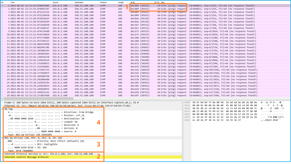
Select the second packet and check the key points:
- Only ICMP echo request packets are captured. Each packet is captured and shown 2 times.
- The original packet header is without the VLAN tag.
- The internal switch inserts additional port VLAN tag 102 that identifies the ingress interface Ethernet1/2.
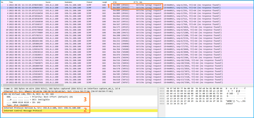
Open the capture file for the interface Ethernet1/9, select the first and the second packets, and check the key points:
- Each ICMP echo reply is captured and shown 2 times.
- The original packet header is without the VLAN tag.
- The internal switch inserts additional port VLAN tag 102 that identifies the egress interface Ethernet1/2.
- The internal switch inserts an additional VN tag.
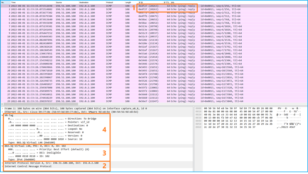
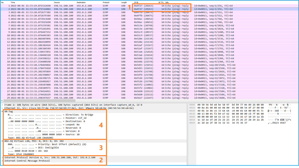
Explanation
If the option All Packets in the Application Capture Direction is selected, 2 simultaneous packet captures related to the selected application port Ethernet1/2 are configured: a capture on the front interface Ethernet1/2 and a capture on selected backplane interfaces.
When a packet capture on a front interface is configured, the switch simultaneously captures each packet twice:
- After the insertion of the port VLAN tag.
- After the insertion of the VN tag.
In the order of operations, the VN tag is inserted at a later stage than the port VLAN tag insertion. But in the capture file, the packet with the VN tag is shown earlier than the packet with the port VLAN tag. In this example, the VLAN tag 102 in ICMP echo request packets identifies Ethernet1/2 as the ingress interface.
When a packet capture on a backplane interface is configured, the switch simultaneously captures each packet twice. The internal switch receives packets that are already tagged by the application on the security module with the port VLAN tag and the VN tag. The port VLAN tag identifies the egress interface that the internal chassis uses to forward the packets to the network. In this example, the VLAN tag 102 in ICMP echo reply packets identifies Ethernet1/2 as the egress interface.
The internal switch removes the VN tag and the internal interface VLAN tag before the packets are forwarded to the network.
This table summarizes the task:
|
Task |
Capture point |
Internal port VLAN in captured packets |
Direction |
Captured traffic |
|
Configure and verify captures on application and application port Ethernet1/2 |
Backplane interfaces |
102 |
Ingress only |
ICMP echo replies from host 198.51.100.100 to host 192.0.2.100 |
|
Interface Ethernet1/2 |
102 |
Ingress only |
ICMP echo requests from host 192.0.2.100 to host 198.51.100.100 |
Packet Capture on a Subinterface of a Physical or Port-channel Interface
Use the FCM and CLI to configure and verify a packet capture on subinterface Ethernet1/2.205 or port-channel subinterface Portchannel1.207. Subinterfaces and captures on subinterfaces are supported only for the FTD application in container mode. In this case, a packet capture on Ethernet1/2.205 and Portchannel1.207 are configured.
Topology, packet flow, and the capture points
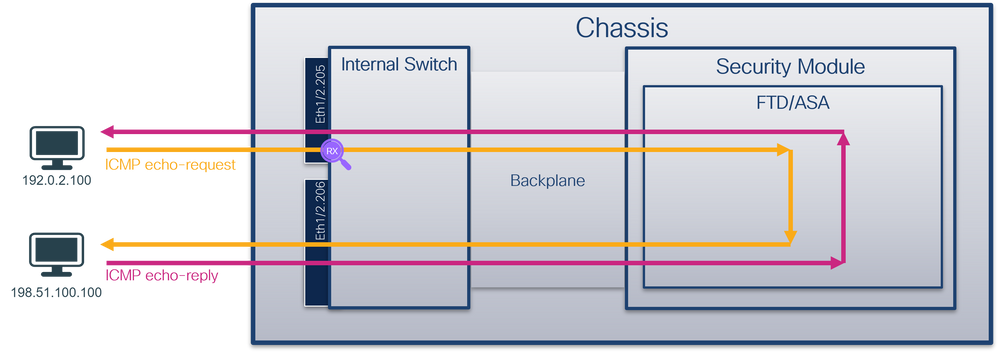
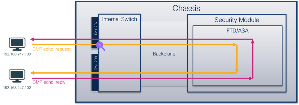
Configuration
FCM
Perform these steps on FCM to configure a packet capture on the FTD application and the application port Ethernet1/2:
- Use Tools > Packet Capture > Capture Session to create a new capture session:

- Select the specific application instance ftd1, the subinterface Ethernet1/2.205, provide the session name, and click Save and Run to activate the capture:
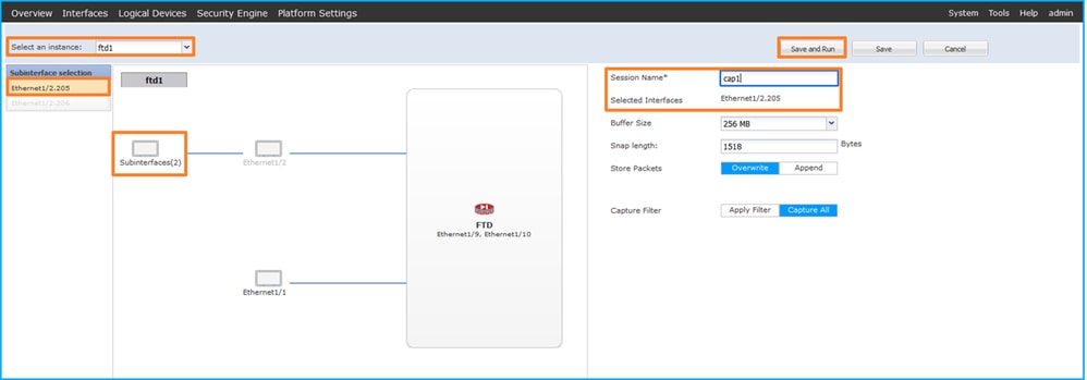
3. In the case of a port-channel subinterface, due to the Cisco bug ID CSCvq33119 subinterfaces are not visible in the FCM. Use the FXOS CLI to configure captures on port-channel subinterfaces.
FXOS CLI
Perform these steps on FXOS CLI to configure a packet capture on subinterfaces Ethernet1/2.205 and Portchannel1.207:
- Identify the application type and identifier:
firepower# scope ssa
firepower /ssa #  show app-instance
App Name   Identifier Slot ID    Admin State Oper State       Running Version Startup Version Deploy Type Turbo Mode Profile Name Cluster State   Cluster Role
---------- ---------- ---------- ----------- ---------------- --------------- --------------- ----------- ---------- ------------ --------------- ------------
ftd        ftd1       1          Enabled     Online           7.2.0.82        7.2.0.82        Container   No         RP20         Not Applicable  None
ftd        ftd2       1          Enabled     Online           7.2.0.82        7.2.0.82        Container   No         RP20         Not Applicable  None
- In the case of a port-channel interface, identify its member interfaces:
firepower# connect fxos
<output skipped>
firepower(fxos)# show port-channel summary
Flags:  D - Down        P - Up in port-channel (members)
        I - Individual  H - Hot-standby (LACP only)
        s - Suspended   r - Module-removed
        S - Switched    R - Routed
        U - Up (port-channel)
        M - Not in use. Min-links not met
--------------------------------------------------------------------------------
Group Port-       Type     Protocol  Member Ports
      Channel
--------------------------------------------------------------------------------
1     Po1(SU)     Eth      LACP      Eth1/3(P)    Eth1/3(P)
- Create a capture session:
firepower# scope packet-capture
firepower /packet-capture # create session cap1
firepower /packet-capture/session* # create phy-port Eth1/2
firepower /packet-capture/session/phy-port* # set app ftd
firepower /packet-capture/session/phy-port* # set app-identifier ftd1
firepower /packet-capture/session/phy-port* # set subinterface 205
firepower /packet-capture/session/phy-port* # up
firepower /packet-capture/session* # enable
firepower /packet-capture/session* # commit
firepower /packet-capture/session #
For port-channel subinterfaces, create a packet capture for each port-channel member interface:
firepower#  scope packet-capture
firepower /packet-capture # create filter vlan207
firepower /packet-capture/filter* # set ovlan 207
firepower /packet-capture/filter* # up
firepower /packet-capture* # create session cap1
firepower /packet-capture/session*  create phy-port Eth1/3
firepower /packet-capture/session/phy-port* # set app ftd
firepower /packet-capture/session/phy-port* # set app-identifier ftd1
firepower /packet-capture/session/phy-port* # set subinterface 207
firepower /packet-capture/session/phy-port* # up
firepower /packet-capture/session* # create phy-port Eth1/4
firepower /packet-capture/session/phy-port* # set app ftd
firepower /packet-capture/session/phy-port* # set app-identifier ftd1
firepower /packet-capture/session/phy-port* # set subinterface 207
firepower /packet-capture/session/phy-port* # up
firepower /packet-capture/session* # enable
firepower /packet-capture/session* # commit
firepower /packet-capture/session #
Verification
FCM
Verify the Interface Name, ensure that the Operational Status is up and that the File Size (in bytes) increases:

Port-channel subinterface captures configured on FXOS CLI are also visible on FCM; however, they cannot be edited:

FXOS CLI
Verify the capture details in scope packet-capture:
firepower# scope packet-capture
firepower /packet-capture # show session cap1

Traffic Monitoring Session:
    Packet Capture Session Name: cap1
    Session: 1
    Admin State: Enabled
    Oper State: Up
    Oper State Reason: Active
    Config Success: Yes
    Config Fail Reason:
    Append Flag: Overwrite
    Session Mem Usage: 256  MB
    Session Pcap Snap Len: 1518  Bytes
    Error Code: 0
    Drop Count: 0

Physical ports involved in Packet Capture:
    Slot Id: 1
    Port Id: 2
    Pcapfile: /workspace/packet-capture/session-1/cap1-ethernet-1-2-0.pcap
    Pcapsize: 9324  bytes
    Filter:
    Sub Interface: 205
    Application Instance Identifier: ftd1
    Application Name: ftd
Port-channel 1 with member interfaces Ethernet1/3 and Ethernet1/4:
firepower# scope packet-capture
firepower /packet-capture # show session cap1

Traffic Monitoring Session:
    Packet Capture Session Name: cap1
    Session: 1
    Admin State: Enabled
    Oper State: Up
    Oper State Reason: Active
    Config Success: Yes
    Config Fail Reason:
    Append Flag: Overwrite
    Session Mem Usage: 256  MB
    Session Pcap Snap Len: 1518  Bytes
    Error Code: 0
    Drop Count: 0

Physical ports involved in Packet Capture:
    Slot Id: 1
    Port Id: 3
    Pcapfile: /workspace/packet-capture/session-1/cap1-ethernet-1-3-0.pcap
    Pcapsize: 160  bytes
    Filter:
    Sub Interface: 207
    Application Instance Identifier: ftd1
    Application Name: ftd
    Slot Id: 1
    Port Id: 4
    Pcapfile: /workspace/packet-capture/session-1/cap1-ethernet-1-4-0.pcap
    Pcapsize: 624160  bytes
    Filter:
    Sub Interface: 207
    Application Instance Identifier: ftd1
    Application Name: ftd
Collect capture files
Perform the steps in the section Collect Firepower 4100/9300 Internal Switch Capture Files.
Capture file analysis
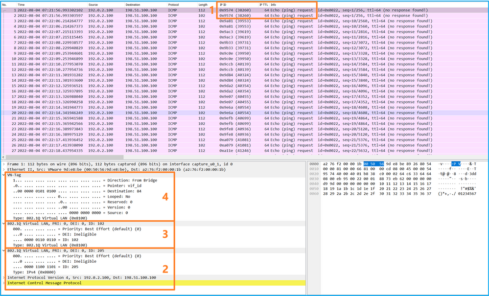
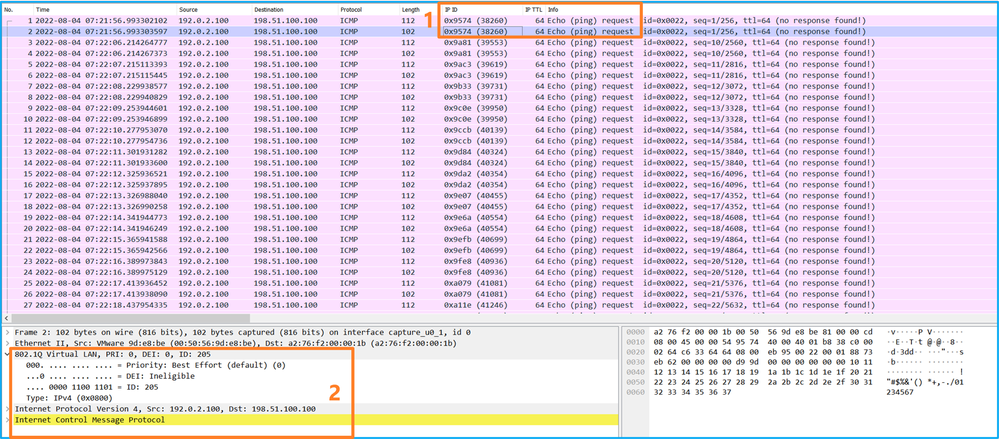
Use a packet capture file reader application to open the capture file. Select the first packet and check the key points:
- Only ICMP echo request packets are captured. Each packet is captured and shown 2 times.
- The original packet header has the VLAN tag 205.
- The internal switch inserts additional port VLAN tag 102 that identifies the ingress interface Ethernet1/2.
- The internal switch inserts an additional VN tag.
Select the second packet and check the key points:
- Only ICMP echo request packets are captured. Each packet is captured and shown 2 times.
- The original packet header has the VLAN tag 205.
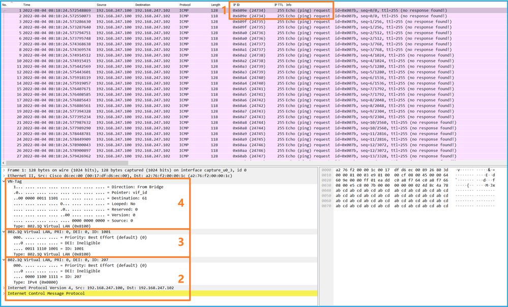
Now open the capture files for Portchannel1.207. Select the first packet and check the key points
- Only ICMP echo request packets are captured. Each packet is captured and shown 2 times.
- The original packet header has the VLAN tag 207.
- The internal switch inserts an additional port VLAN tag 1001 that identifies the ingress interface Portchannel1.
- The internal switch inserts an additional VN tag.
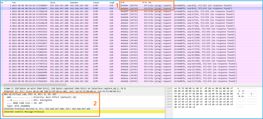
Select the second packet and check the key points:
- Only ICMP echo request packets are captured. Each packet is captured and shown 2 times.
- The original packet header has the VLAN tag 207.
Explanation
When a packet capture on a front interface is configured, the switch simultaneously captures each packet twice:
- After the insertion of the port VLAN tag.
- After the insertion of the VN tag.
In the order of operations, the VN tag is inserted at a later stage than the port VLAN tag insertion. But in the capture file, the packet with the VN tag is shown earlier than the packet with the port VLAN tag. Additionally, in the case of subinterfaces, in the capture files, every second packet does not contain the port VLAN tag.
This table summarizes the task:
|
Task |
Capture point |
Internal port VLAN in captured packets |
Direction |
Captured traffic |
|
Configure and verify a packet capture on subinterface Ethernet1/2.205 |
Ethernet1/2.205 |
102 |
Ingress only |
ICMP echo requests from host 192.0.2.100 to host 198.51.100.100 |
|
Configure and verify a packet capture on Portchannel1 subinterface with member interfaces Ethernet1/3 and Ethernet1/4 |
Ethernet1/3 Ethernet1/4 |
1001 |
Ingress only |
ICMP echo requests from 192.168.207.100 to host 192.168.207.102 |
Packet Capture Filters
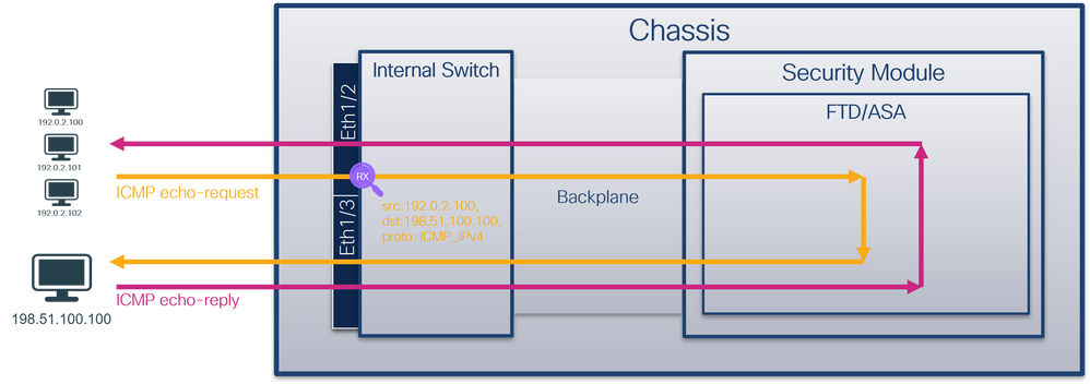
Use the FCM and CLI to configure and verify a packet capture on interface Ethernet1/2 with a filter.
Topology, packet flow, and the capture points
Configuration
FCM
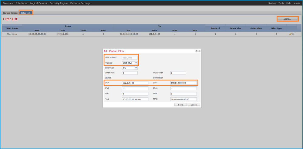
Perform these steps on FCM to configure a capture filter for ICMP echo request packets from host 192.0.2.100 to host 198.51.100.100 and apply it to packet capture on interface Ethernet1/2:
-
Use Tools > Packet Capture > Filter List > Add Filter to create a capture filter.
- Specify the Filter Name, Protocol, Source IPv4, Destination IPv4 and click Save:
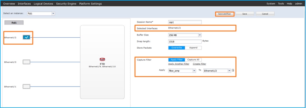
- Use Tools > Packet Capture > Capture Session to create a new capture session:

- Select Ethernet1/2, provide the Session Name, apply the capture filter and click Save and Run to activate the capture:
FXOS CLI
Perform these steps on FXOS CLI to configure packet captures on backplane interfaces:
- Identify the application type and identifier:
firepower# scope ssa
firepower /ssa#  show app-instance
App Name   Identifier Slot ID    Admin State Oper State       Running Version Startup Version Deploy Type Turbo Mode Profile Name Cluster State   Cluster Role
---------- ---------- ---------- ----------- ---------------- --------------- --------------- ----------- ---------- ------------ --------------- ------------
ftd        ftd1       1          Enabled     Online           7.2.0.82        7.2.0.82        Native      No                      Not Applicable  None
2. Identify the IP protocol number in https://www.iana.org/assignments/protocol-numbers/protocol-numbers.xhtml. In this case, the ICMP protocol number is 1.
3. Create a capture session:
-
firepower# scope packet-capture
firepower /packet-capture # create filter filter_icmp
firepower /packet-capture/filter* # set destip 198.51.100.100
firepower /packet-capture/filter* # set protocol 1
firepower /packet-capture/filter* # set srcip 192.0.2.100
firepower /packet-capture/filter* # exit
firepower /packet-capture* # create session cap1
firepower /packet-capture/session* # create phy-port Ethernet1/2
firepower /packet-capture/session/phy-port* # set app ftd
firepower /packet-capture/session/phy-port* # set app-identifier ftd1
firepower /packet-capture/session/phy-port* # set filter filter_icmp
firepower /packet-capture/session/phy-port* # exit
firepower /packet-capture/session* # enable
firepower /packet-capture/session* # commit
firepower /packet-capture/session #
Verification
FCM
Verify the Interface Name, ensure that the Operational Status is up and that the File Size (in bytes) increases:

Verify the Interface Name, the Filter, ensure the Operational Status is up, and the File Size (in bytes) increases in Tools > Packet Capture > Capture Session:

FXOS CLI
Verify the capture details in scope packet-capture:
firepower# scope packet-capture
firepower /packet-capture # show filter detail

Configure a filter for packet capture:
    Name: filter_icmp
    Protocol: 1
    Ivlan: 0
    Ovlan: 0
    Src Ip: 192.0.2.100
    Dest Ip: 198.51.100.100
    Src MAC: 00:00:00:00:00:00
    Dest MAC: 00:00:00:00:00:00
    Src Port: 0
    Dest Port: 0
    Ethertype: 0
    Src Ipv6: ::
    Dest Ipv6: ::
firepower /packet-capture # show session cap1

Traffic Monitoring Session:
    Packet Capture Session Name: cap1
    Session: 1
    Admin State: Enabled
    Oper State: Up
    Oper State Reason: Active
    Config Success: Yes
    Config Fail Reason:
    Append Flag: Overwrite
    Session Mem Usage: 256  MB
    Session Pcap Snap Len: 1518  Bytes
    Error Code: 0
    Drop Count: 0

Physical ports involved in Packet Capture:
    Slot Id: 1
    Port Id: 2
    Pcapfile: /workspace/packet-capture/session-1/cap1-ethernet-1-2-0.pcap
    Pcapsize: 213784  bytes
    Filter: filter_icmp
    Sub Interface: 0
    Application Instance Identifier: ftd1
    Application Name: ftd
Collect capture files
Perform the steps in the section Collect Firepower 4100/9300 Internal Switch Capture Files.
Capture file analysis
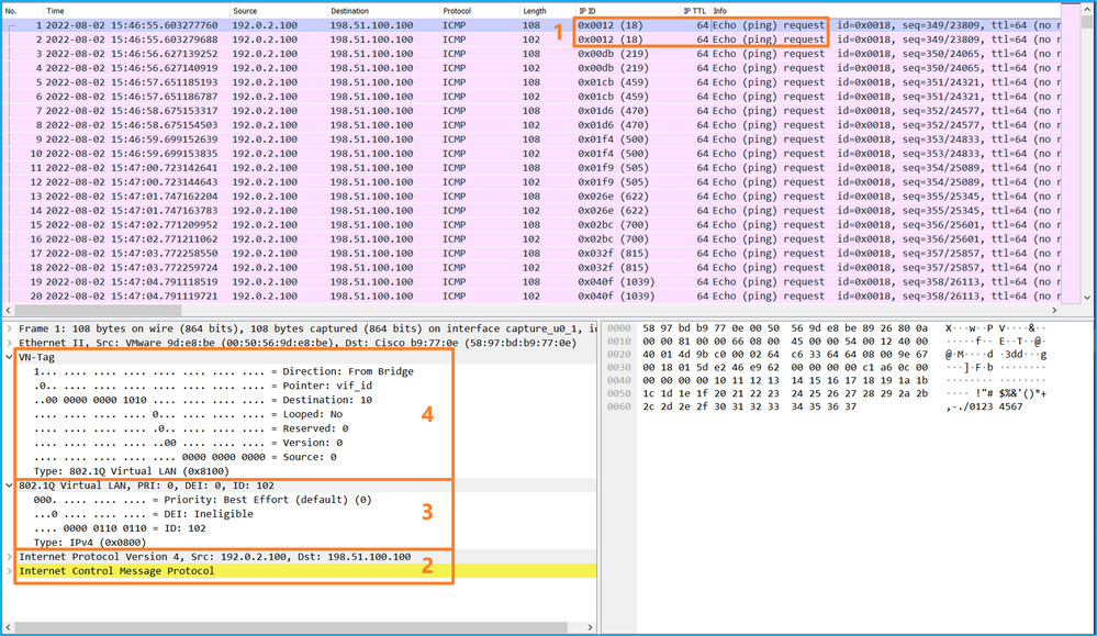
Use a packet capture file reader application to open the capture file. Select the first packet and check the key points
- Only ICMP echo request packets are captured. Each packet is captured and shown 2 times.
- The original packet header is without the VLAN tag.
- The internal switch inserts additional port VLAN tag 102 that identifies the ingress interface Ethernet1/2.
- The internal switch inserts an additional VN tag.
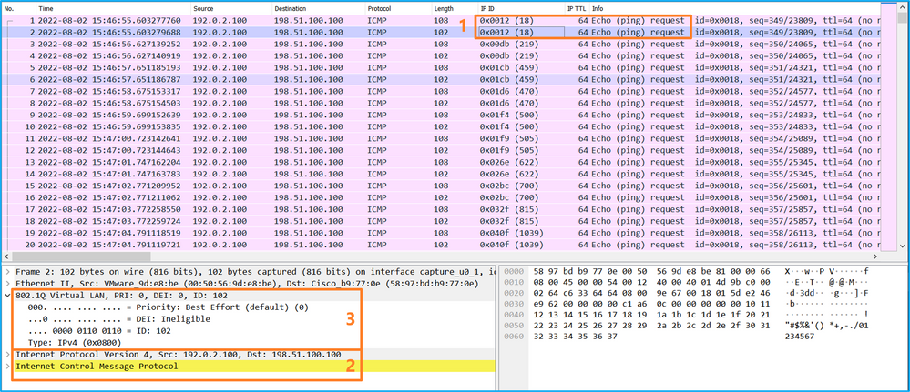
Select the second packet, and check the key points:
- Only ICMP echo request packets are captured. Each packet is captured and shown 2 times.
- The original packet header is without the VLAN tag.
- The internal switch inserts additional port VLAN tag 102 that identifies the ingress interface Ethernet1/2.
Explanation
When a packet capture on a front interface is configured, the switch simultaneously captures each packet twice:
- After the insertion of the port VLAN tag.
- After the insertion of the VN tag.
In the order of operations, the VN tag is inserted at a later stage than the port VLAN tag insertion. But in the capture file, the packet with the VN tag is shown earlier than the packet with the port VLAN tag.
When a capture filter is applied only the packets that match the filter in the ingress direction are captured.
This table summarizes the task:
|
Task |
Capture point |
Internal port VLAN in captured packets |
Direction |
User filter |
Captured traffic |
|
Configure and verify a packet capture with a filter on the front interface Ethernet1/2 |
Ethernet1/2 |
102 |
Ingress only |
Protocol: ICMP Source:192.0.2.100 Destination: 198.51.100.100 |
ICMP echo requests from host 192.0.2.100 to host 198.51.100.100 |
Collect Firepower 4100/9300 Internal Switch Capture Files
FCM
Perform these steps on FCM to collect internal switch capture files:
- Click the Disable Session button to stop the active capture:

- Ensure the operational state is DOWN - Session_Admin_Shut:

- Click Download to download the capture file:

In the case of port-channel interfaces, repeat this step for each member interface.
FXOS CLI
Perform these steps on the FXOS CLI to collect capture files:
- Stop the active capture:
firepower# scope packet-capture
firepower /packet-capture # scope session cap1
firepower /packet-capture/session # disable
firepower /packet-capture/session* # commit
firepower /packet-capture/session # up
firepower /packet-capture # show session cap1 detail

Traffic Monitoring Session:
    Packet Capture Session Name: cap1
    Session: 1
    Admin State: Disabled
    Oper State: Down
    Oper State Reason: Admin Disable
    Config Success: Yes
    Config Fail Reason:
    Append Flag: Overwrite
    Session Mem Usage: 256  MB
    Session Pcap Snap Len: 1518  Bytes
    Error Code: 0
    Drop Count: 0

Physical ports involved in Packet Capture:
    Slot Id: 1
    Port Id: 2
    Pcapfile: /workspace/packet-capture/session-1/cap1-ethernet-1-2-0.pcap
    Pcapsize: 115744  bytes
    Filter:
    Sub Interface: 0
    Application Instance Identifier: ftd1
    Application Name: ftd
- Upload the capture file from the local-mgmt command scope:
firepower# connect local-mgmt
firepower(local-mgmt)# copy /packet-capture/session-1/cap1-ethernet-1-2-0.pcap ?
  ftp:        Dest File URI
  http:       Dest File URI
  https:      Dest File URI
  scp:        Dest File URI
  sftp:       Dest File URI
  tftp:       Dest File URI
  usbdrive:   Dest File URI
  volatile:   Dest File URI
  workspace:  Dest File URI

firepower(local-mgmt)# copy /packet-capture/session-1/cap1-ethernet-1-2-0.pcap ftp://ftpuser@10.10.10.1/cap1-ethernet-1-2-0.pcap
Password:
In the case of port-channel interfaces, copy the capture file for each member interface.
Guidelines, Limitations, and Best Practices for Internal Switch Packet Capture
For the guidelines and limitations related to Firepower 4100/9300 internal switch capture refer to the Cisco Firepower 4100/9300 FXOS Chassis Manager Configuration Guide or Cisco Firepower 4100/9300 FXOS CLI Configuration Guide, chapter Troubleshooting, section Packet Capture.
This is the list of best practices based on the usage of packet capture in TAC cases:
- Be aware of guidelines and limitations.
- Capture packets on all port-channel member interfaces and analyze all capture files.
- Use capture filters.
- Consider the impact of NAT on packet IP addresses when a capture filter is configured.
- Increase or decrease the Snap Len that specifies frame size in case it differs from the default value of 1518 bytes. Shorter size results in an increased number of captured packets and vice versa.
- Adjust the Buffer Size as needed.
- Be aware of the Drop Count on FCM or FXOS CLI. Once the buffer size limit is reached, the drop count counter increases.
- Use the filter !vntag on Wireshark to display only packets without the VN-tag. This is useful to hide VN-tagged packets in the front interface packet capture files.
- Use the filter frame.number&1 on Wireshark to display only odd frames. This is useful to hide duplicate packets in the backplane interface packet capture files.
- In the case of protocols like TCP, Wireshark by default applies colorization rules that display packets with specific conditions in different colors. In the case of internal switch captures due to duplicate packets in capture files, the packet can be colored and marked in a false-positive way. If you analyze packet capture files and apply any filter, then export the displayed packets to a new file and open the new file instead.
Configuration and Verification on Secure Firewall 3100/4200
Unlike Firepower 4100/9300, the internal switch captures on the Secure Firewall 3100/4200 are configured on the application command line interface via the capture <name> switch command, where the switch option specifies that the captures are configured on the internal switch.
This is the capture command with the switch option:
> capture cap_sw switch ?
  buffer         Configure size of capture buffer, default is 256MB
  ethernet-type  Capture Ethernet packets of a particular type, default is IP
  interface      Capture packets on a specific interface
  ivlan          Inner Vlan
  match          Capture packets based on match criteria
  ovlan          Outer Vlan
  packet-length  Configure maximum length to save from each packet, default is
                 64 bytes
  real-time      Display captured packets in real-time. Warning: using this
                 option with a slow console connection may result in an
                 excessive amount of non-displayed packets due to performance
                 limitations.
  stop           Stop packet capture
  trace          Trace the captured packets
  type           Capture packets based on a particular type
  <cr>
General steps for packet capture configuration are as follows:
- Specify an ingress interface:
Switch capture configuration accepts the ingress interface nameif. The user can specify data interfaces names, internal uplink, or the management interfaces:
> capture capsw switch interface ?
Available interfaces to listen:
  in_data_uplink1  Capture packets on internal data uplink1 interface
  in_mgmt_uplink1  Capture packets on internal mgmt uplink1 interface
  inside           Name of interface Ethernet1/1.205

  management       Name of interface Management1/1
The Secure Firewall 4200 supports bidirectional captures. The default value is ingress, unless specified otherwise:
> capture capi switch interface inside direction
  both     To capture switch bi-directional traffic
  egress   To capture switch egressing traffic
  ingress  To capture switch ingressing traffic
Additionall, the Secure Firewall 4245 has 2 internal data and 2 management uplink interfaces:
> capture capsw switch interface
  eventing         Name of interface Management1/2
  in_data_uplink1  Capture packets on internal data uplink1 interface
  in_data_uplink2  Capture packets on internal data uplink2 interface
  in_mgmt_uplink1  Capture packets on internal mgmt uplink1 interface
  in_mgmt_uplink2  Capture packets on internal mgmt uplink2 interface
  management       Name of interface Management1/1
- Specify the ethernet frame EtherType. The default EtherType is IP. The ethernet-type option values specify the EtherType:
> capture capsw switch interface inside ethernet-type ?
  802.1Q
  <0-65535>  Ethernet type
  arp
  ip
  ip6
  pppoed
  pppoes
  rarp
  sgt
  vlan
- Specify the match conditions. The capture match option specifies the match criteria:
> capture capsw switch interface inside match ?
  <0-255>  Enter protocol number (0 - 255)
  ah
  eigrp
  esp
  gre
  icmp
  icmp6
  igmp
  igrp
  ip
  ipinip
  ipsec
  mac      Mac-address filter
  nos
  ospf
  pcp
  pim
  pptp
  sctp
  snp
  spi      SPI value
  tcp
  udp
  <cr>
- Specify other optional parameters such as the buffer size, the packet length, and so on.
- Enable the capture. The command no capture <name> switch stop activates the capture:
> capture capsw switch interface inside match ip
> no capture capsw switch stop
- Verify the capture details:
- Administrative status is enabled, and operational status is up and active.
- Packet capture file size Pcapsize increases.
- The number of captured packets in the output of the show capture <cap_name> is non-zero.
- Capture path Pcapfile. The captured packets are automatically saved in the /mnt/disk0/packet-capture/ folder.
- Capture conditions. The software automatically creates capture filters based on capture conditions.
> show capture capsw
27 packet captured on disk using switch capture
Reading of capture file from disk is not supported

> show capture capsw  detail
Packet Capture info
  Name:              capsw
  Session:           1
  Admin State:       enabled
  Oper State:        up
  Oper State Reason: Active
  Config Success:    yes
  Config Fail Reason:
  Append Flag:       overwrite
  Session Mem Usage: 256
  Session Pcap Snap Len: 1518
  Error Code:        0
  Drop Count:        0

Total Physical ports involved in Packet Capture: 1
Physical port:
  Slot Id:           1
  Port Id:           1
  Pcapfile:          /mnt/disk0/packet-capture/sess-1-capsw-ethernet-1-1-0.pcap
  Pcapsize:          18838
  Filter:            capsw-1-1

Packet Capture Filter Info
  Name:              capsw-1-1
  Protocol:          0
  Ivlan:             0
  Ovlan:             205
  Src Ip:            0.0.0.0
  Dest Ip:           0.0.0.0
  Src Ipv6:          ::
  Dest Ipv6:         ::
  Src MAC:           00:00:00:00:00:00
  Dest MAC:          00:00:00:00:00:00
  Src Port:          0
  Dest Port:         0
  Ethertype:         0

Total Physical breakout ports involved in Packet Capture: 0
0 packet captured on disk using switch capture
Reading of capture file from disk is not supported
- Stop the captures when needed:
> capture capsw switch stop
> show capture capsw detail
Packet Capture info
  Name:              capsw
  Session:           1
  Admin State:       disabled
  Oper State:        down
  Oper State Reason: Session_Admin_Shut
  Config Success:    yes
  Config Fail Reason:
  Append Flag:       overwrite
  Session Mem Usage: 256
  Session Pcap Snap Len: 1518
  Error Code:        0
  Drop Count:        0
Total Physical ports involved in Packet Capture: 1

Physical port:
  Slot Id:           1
  Port Id:           1
  Pcapfile:          /mnt/disk0/packet-capture/sess-1-capsw-ethernet-1-1-0.pcap
  Pcapsize:          24
  Filter:            capsw-1-1

Packet Capture Filter Info
  Name:              capsw-1-1
  Protocol:          0
  Ivlan:             0
  Ovlan:             205
  Src Ip:            0.0.0.0
  Dest Ip:           0.0.0.0
  Src Ipv6:          ::
  Dest Ipv6:         ::
  Src MAC:           00:00:00:00:00:00
  Dest MAC:          00:00:00:00:00:00
  Src Port:          0
  Dest Port:         0
  Ethertype:         0

Total Physical breakout ports involved in Packet Capture: 0
0 packet captured on disk using switch capture
Reading of capture file from disk is not supported
8. Collect the capture files. Perform the steps in the section Collect Secure Firewall Internal Switch Capture Files.
In Secure Firewall software version 7.4, the internal switch capture configuration is not supported on the FMC or FDM. In the case of ASA software version 9.18(1) and later, internal switch captures can be configured in ASDM versions 7.18.1.x and later.
These scenarios cover common use cases of Secure Firewall 3100/4200 internal switch captures.
Packet Capture on a Physical or Port-channel Interface
Use the FTD or ASA CLI to configure and verify a packet capture on interface Ethernet1/1 or Portchannel1 interface. Both interfaces have the nameif inside.
Topology, packet flow, and the capture points
Secure Firewall 3100:
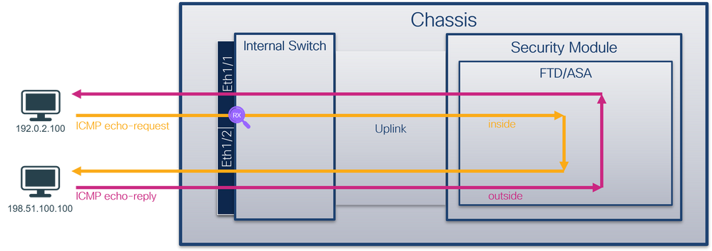
Secure Firewall 4200 with bidirectional captures:
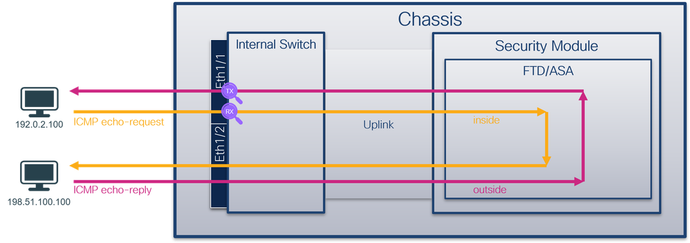
Configuration
Perform these steps on ASA or FTD CLI to configure a packet capture on interface Ethernet1/1 or Port-channel1:
- Verify the nameif:
> show nameif
Interface                Name                     Security
Ethernet1/1              inside                     0
Ethernet1/2              outside                    0
Management1/1            diagnostic                 0
> show nameif
Interface                Name                     Security
Port-channel1            inside                    0
Ethernet1/2              outside                    0
Management1/1            diagnostic                 0
- Create a capture session
> capture capsw switch interface inside
The Secure Firewall 4200 supports capture directionality:
> capture capsw switch interface inside direction ?
  both To capture switch bi-directional traffic
  egress To capture switch egressing traffic
  ingress To capture switch ingressing traffic

> capture capsw switch interface inside direction both
- Enable the capture session:
> no capture capsw switch stop
Verification
Verify the capture session name, administrative and operational state, interface slot, and identifier. Ensure the Pcapsize value in bytes increases and the number of captured packets is non-zero:
> show capture capsw detail
Packet Capture info
  Name:              capsw
  Session:           1
  Admin State:       enabled
  Oper State:        up
  Oper State Reason: Active
  Config Success:    yes
  Config Fail Reason:
  Append Flag:       overwrite
  Session Mem Usage: 256
  Session Pcap Snap Len: 1518
  Error Code:        0
  Drop Count:        0

Total Physical ports involved in Packet Capture: 1

Physical port:
  Slot Id:           1
  Port Id:           1
  Pcapfile:          /mnt/disk0/packet-capture/sess-1-capsw-ethernet-1-1-0.pcap
  Pcapsize:          12653
  Filter:            capsw-1-1

Packet Capture Filter Info
  Name:              capsw-1-1
  Protocol:          0
  Ivlan:             0
  Ovlan:             0
  Src Ip:            0.0.0.0
  Dest Ip:           0.0.0.0
  Src Ipv6:          ::
  Dest Ipv6:         ::
  Src MAC:           00:00:00:00:00:00
  Dest MAC:          00:00:00:00:00:00
  Src Port:          0
  Dest Port:         0
  Ethertype:         0

Total Physical breakout ports involved in Packet Capture: 0

79 packets captured on disk using switch capture

Reading of capture file from disk is not supported
Secure Firewal 4200:
> show cap capsw detail
Packet Capture info
  Name:              capsw
  Session:           1
  Admin State:       enabled
  Oper State:        up
  Oper State Reason: Active
  Config Success:    yes
  Config Fail Reason:
  Append Flag:       overwrite
  Session Mem Usage: 256
  Session Pcap Snap Len: 1518
  Error Code:        0
  Drop Count:        0

Total Physical ports involved in Packet Capture: 1

Physical port:
  Slot Id:           1
  Port Id:           1
  Pcapfile:          /mnt/disk0/packet-capture/sess-1-capsw-ethernet-1-1-0.pcap
  Pcapsize:          0
  Direction:         both
  Drop:              disable
  Filter:            capsw-1-1

Packet Capture Filter Info
  Name:              capsw-1-1
  Protocol:          0
  Ivlan:             0
  Ovlan:             0
  Src Ip:            0.0.0.0
  Dest Ip:           0.0.0.0
  Src Ipv6:          ::
  Dest Ipv6:         ::
  Src MAC:           00:00:00:00:00:00
  Dest MAC:          00:00:00:00:00:00
  Src Port:          0
  Dest Port:         0
  Ethertype:         0

Total Physical breakout ports involved in Packet Capture: 0
33 packet captured on disk using switch capture

Reading of capture file from disk is not supported
In the case of Port-channel1 the capture is configured on all member interfaces:
> show capture capsw detail
Packet Capture info
  Name:              capsw
  Session:           1
  Admin State:       enabled
  Oper State:        up
  Oper State Reason: Active
  Config Success:    yes
  Config Fail Reason:
  Append Flag:       overwrite
  Session Mem Usage: 256
  Session Pcap Snap Len: 1518
  Error Code:        0
  Drop Count:        0

Total Physical ports involved in Packet Capture: 2

Physical port:
  Slot Id:           1
  Port Id:           4
  Pcapfile:          /mnt/disk0/packet-capture/sess-1-capsw-ethernet-1-4-0.pcap
  Pcapsize:          28824
  Filter:            capsw-1-4

Packet Capture Filter Info
  Name:              capsw-1-4
  Protocol:          0
  Ivlan:             0
  Ovlan:             0
  Src Ip:            0.0.0.0
  Dest Ip:           0.0.0.0
  Src Ipv6:          ::
  Dest Ipv6:         ::
  Src MAC:           00:00:00:00:00:00
  Dest MAC:          00:00:00:00:00:00
  Src Port:          0
  Dest Port:         0
  Ethertype:         0

Physical port:
  Slot Id:           1
  Port Id:           3
  Pcapfile:          /mnt/disk0/packet-capture/sess-1-capsw-ethernet-1-3-0.pcap
  Pcapsize:          18399
  Filter:            capsw-1-3

Packet Capture Filter Info
  Name:              capsw-1-3
  Protocol:          0
  Ivlan:             0
  Ovlan:             0
  Src Ip:            0.0.0.0
  Dest Ip:           0.0.0.0
  Src Ipv6:          ::
  Dest Ipv6:         ::
  Src MAC:           00:00:00:00:00:00
  Dest MAC:          00:00:00:00:00:00
  Src Port:          0
  Dest Port:         0
  Ethertype:         0

Total Physical breakout ports involved in Packet Capture: 0

56 packet captured on disk using switch capture

Reading of capture file from disk is not supported
The port-channel member interfaces can be verified in the FXOS local-mgmt command shell via the show portchannel summary command:
> connect fxos
…
firewall# connect local-mgmt
firewall(local-mgmt)# show portchannel summary
Flags:  D - Down        P - Up in port-channel (members)
I - Individual  H - Hot-standby (LACP only)
s - Suspended   r - Module-removed
S - Switched    R - Routed
U - Up (port-channel)
M - Not in use. Min-links not met
-------------------------------------------------------------------------------
Group Port-       Type     Protocol  Member Ports
      Channel
--------------------------------------------------------------------------------
1     Po1(U)      Eth      LACP      Eth1/3(P)    Eth1/4(P)

LACP KeepAlive Timer:
--------------------------------------------------------------------------------
      Channel  PeerKeepAliveTimerFast
--------------------------------------------------------------------------------
1     Po1(U)      False

Cluster LACP Status:
--------------------------------------------------------------------------------
      Channel  ClusterSpanned  ClusterDetach  ClusterUnitID  ClusterSysID
--------------------------------------------------------------------------------
1     Po1(U)      False          False          0            clust
To access the FXOS on ASA, run the connect fxos admin command. In the case of multi-context, run the command in the admin context.
Collect capture files
Perform the steps in the section Collect Secure Firewall Internal Switch Capture Files.
Capture file analysis
Use a packet capture file reader application to open the capture files for Ethernet1/1. In this example, the packets capture on the Secure Firewall 3100 are analyzed. Select the first packet and check the key points:
- Only ICMP echo request packets are captured.
- The original packet header is without the VLAN tag.
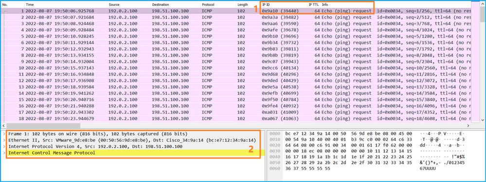
Open the capture files for Portchannel1 member interfaces. Select the first packet and check the key points:
- Only ICMP echo request packets are captured.
- The original packet header is without the VLAN tag.
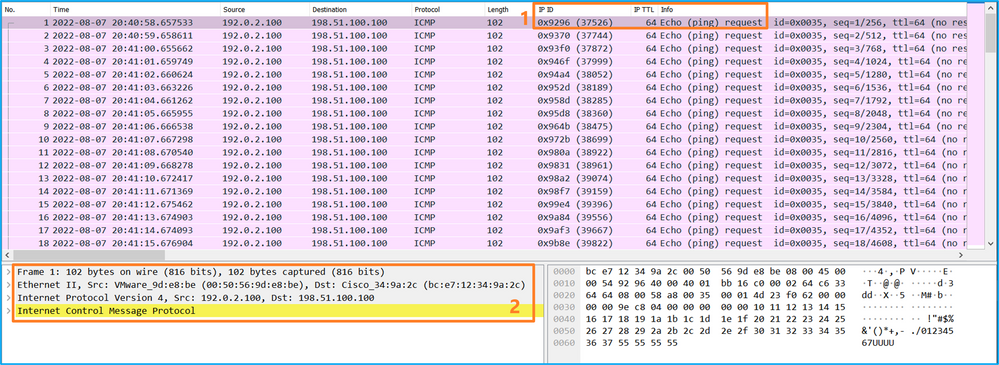
Explanation
The switch captures are configured on interfaces Ethernet1/1 or Portchannel1.
This table summarizes the task:
|
Task |
Capture point |
Internal filter |
Direction |
Captured traffic |
|
Configure and verify a packet capture on interface Ethernet1/1 |
Ethernet1/1 |
None |
Ingress only* |
ICMP echo requests from host 192.0.2.100 to host 198.51.100.100 |
|
Configure and verify a packet capture on interface Portchannel1 with member interfaces Ethernet1/3 and Ethernet1/4 |
Ethernet1/3 Ethernet1/4 |
None |
Ingress only* |
ICMP echo requests from host 192.0.2.100 to host 198.51.100.100 |
* Unlike 3100, the Secure Firewall 4200 supports bidirectional (ingress and egress) captures.
Packet Capture on a Subinterface of a Physical or Port-channel Interface
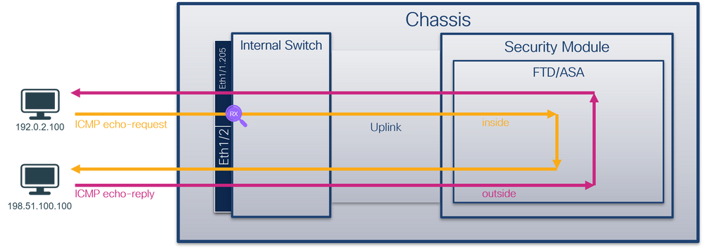
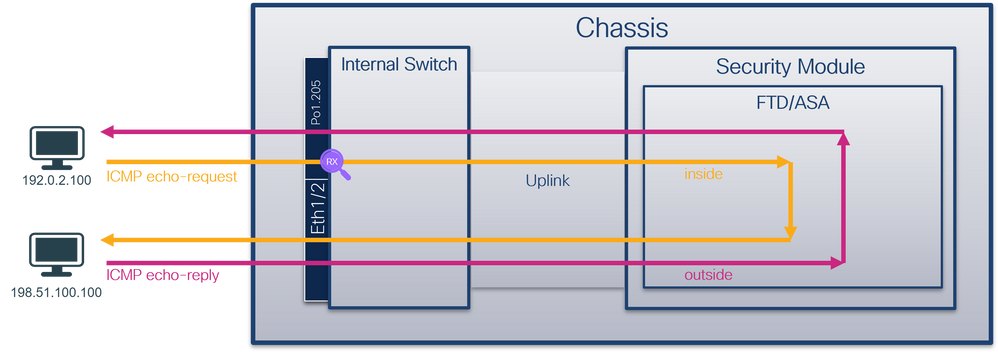
Use the FTD or ASA CLI to configure and verify a packet capture on subinterfaces Ethernet1/1.205 or Portchannel1.205. Both subinterfaces have the nameif inside.
Topology, packet flow, and the capture points
Secure Firewall 3100:
Secure Firewall 4200:
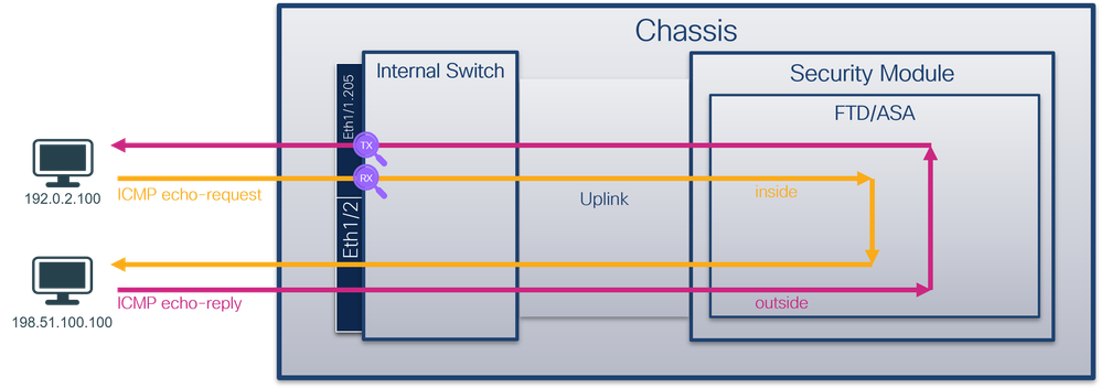
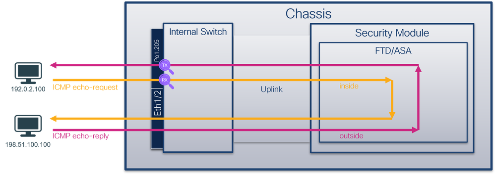
Configuration
Perform these steps on ASA or FTD CLI to configure a packet capture on interface Ethernet1/1 or Port-channel1:
- Verify the nameif:
> show nameif
Interface                Name                     Security
Ethernet1/1.205          inside                     0
Ethernet1/2              outside                    0
Management1/1            diagnostic                 0
> show nameif
Interface                Name                     Security
Port-channel1.205        inside                     0
Ethernet1/2              outside                    0
Management1/1            diagnostic                 0
- Create a capture session:
> capture capsw switch interface inside
The Secure Firewall 4200 supports capture directionality:
> capture capsw switch interface inside direction ?
  both To capture switch bi-directional traffic
  egress To capture switch egressing traffic
  ingress To capture switch ingressing traffic

> capture capsw switch interface inside direction both
3. Enable the capture session:
> no capture capsw switch stop
Verification
Verify the capture session name, administrative and operational state, interface slot, and identifier. Ensure the Pcapsize value in bytes increases and the number of captured packets is non-zero:
> show capture capsw detail
Packet Capture info
  Name:              capsw
  Session:           1
  Admin State:       enabled
  Oper State:        up
  Oper State Reason: Active
  Config Success:    yes
  Config Fail Reason:
  Append Flag:       overwrite
  Session Mem Usage: 256
  Session Pcap Snap Len: 1518
  Error Code:        0
  Drop Count:        0

Total Physical ports involved in Packet Capture: 1

Physical port:
  Slot Id:           1
  Port Id:           1
  Pcapfile:          /mnt/disk0/packet-capture/sess-1-capsw-ethernet-1-1-0.pcap
  Pcapsize:          6360
  Filter:            capsw-1-1

Packet Capture Filter Info
  Name:              capsw-1-1
  Protocol:          0
  Ivlan:             0
  Ovlan:             205
  Src Ip:            0.0.0.0
  Dest Ip:           0.0.0.0
  Src Ipv6:          ::
  Dest Ipv6:         ::
  Src MAC:           00:00:00:00:00:00
  Dest MAC:          00:00:00:00:00:00
  Src Port:          0
  Dest Port:         0
  Ethertype:         0

Total Physical breakout ports involved in Packet Capture: 0

46 packets captured on disk using switch capture

Reading of capture file from disk is not supported
In this case, a filter with outer VLAN Ovlan=205 is created and applied to the interface.
In the case of Port-channel1 the capture with a filter Ovlan=205 is configured on all member interfaces:
> show capture capsw detail
Packet Capture info
  Name:              capsw
  Session:           1
  Admin State:       enabled
  Oper State:        up
  Oper State Reason: Active
  Config Success:    yes
  Config Fail Reason:
  Append Flag:       overwrite
  Session Mem Usage: 256
  Session Pcap Snap Len: 1518
  Error Code:        0
  Drop Count:        0

Total Physical ports involved in Packet Capture: 2

Physical port:
  Slot Id:           1
  Port Id:           4
  Pcapfile:          /mnt/disk0/packet-capture/sess-1-capsw-ethernet-1-4-0.pcap
  Pcapsize:          23442
  Filter:            capsw-1-4

Packet Capture Filter Info
  Name:              capsw-1-4
  Protocol:          0
  Ivlan:             0
  Ovlan:             205
  Src Ip:            0.0.0.0
  Dest Ip:           0.0.0.0
  Src Ipv6:          ::
  Dest Ipv6:         ::
  Src MAC:           00:00:00:00:00:00
  Dest MAC:          00:00:00:00:00:00
  Src Port:          0
  Dest Port:         0
  Ethertype:         0

Physical port:
  Slot Id:           1
  Port Id:           3
  Pcapfile:          /mnt/disk0/packet-capture/sess-1-capsw-ethernet-1-3-0.pcap
  Pcapsize:          5600
  Filter:            capsw-1-3

Packet Capture Filter Info
  Name:              capsw-1-3
  Protocol:          0
  Ivlan:             0
  Ovlan:             205
  Src Ip:            0.0.0.0
  Dest Ip:           0.0.0.0
  Src Ipv6:          ::
  Dest Ipv6:         ::
  Src MAC:           00:00:00:00:00:00
  Dest MAC:          00:00:00:00:00:00
  Src Port:          0
  Dest Port:         0
  Ethertype:         0

Total Physical breakout ports involved in Packet Capture: 0

49 packet captured on disk using switch capture

Reading of capture file from disk is not supported
The port-channel member interfaces can be verified in the FXOS local-mgmt command shell via the show portchannel summary command:
> connect fxos
…
firewall# connect local-mgmt
firewall(local-mgmt)# show portchannel summary
Flags:  D - Down        P - Up in port-channel (members)
I - Individual  H - Hot-standby (LACP only)
s - Suspended   r - Module-removed
S - Switched    R - Routed
U - Up (port-channel)
M - Not in use. Min-links not met
-------------------------------------------------------------------------------
Group Port-       Type     Protocol  Member Ports
      Channel
--------------------------------------------------------------------------------
1     Po1(U)      Eth      LACP      Eth1/3(P)    Eth1/4(P)

LACP KeepAlive Timer:
--------------------------------------------------------------------------------
      Channel  PeerKeepAliveTimerFast
--------------------------------------------------------------------------------
1     Po1(U)      False

Cluster LACP Status:
--------------------------------------------------------------------------------
      Channel  ClusterSpanned  ClusterDetach  ClusterUnitID  ClusterSysID
--------------------------------------------------------------------------------
1     Po1(U)      False          False          0            clust
To access the FXOS on ASA, run the connect fxos admin command. In the case of multi-context, run this command in the admin context.
Collect capture files
Perform the steps in the section Collect Secure Firewall Internal Switch Capture Files.
Capture file analysis
Use a packet capture file reader application to open the capture files for Ethernet1/1.205. In this example, the packets capture on the Secure Firewall 3100 are analyzed. Select the first packet and check the key points:
- Only ICMP echo request packets are captured.
- The original packet header has VLAN tag 205.
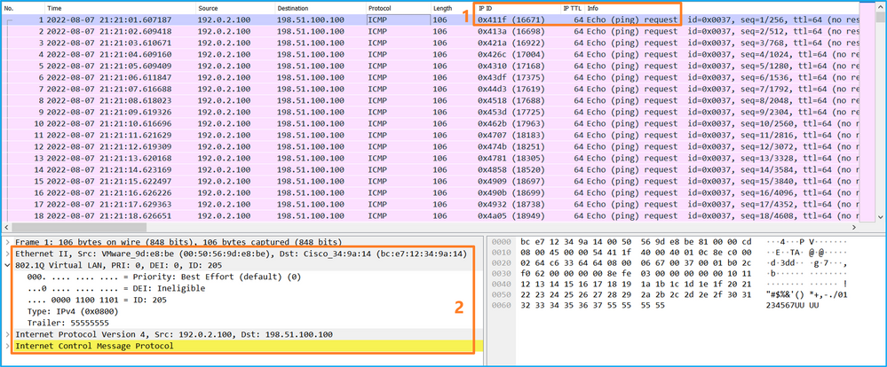
Open the capture files for Portchannel1 member interfaces. Select the first packet and check the key points:
- Only ICMP echo request packets are captured.
- The original packet header has VLAN tag 205.
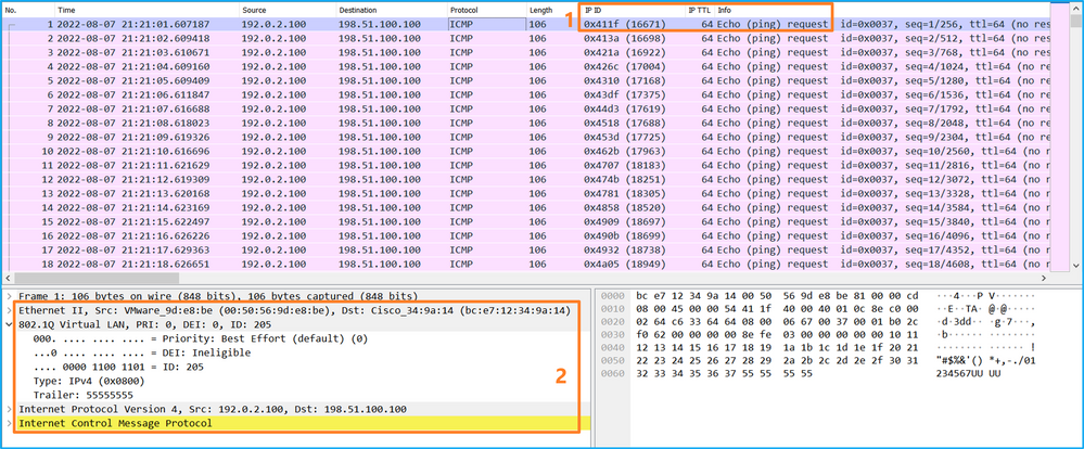
Explanation
The switch captures are configured on subinterfaces Ethernet1/1.205 or Portchannel1.205 with a filter that matches outer VLAN 205.
This table summarizes the task:
|
Task |
Capture point |
Internal filter |
Direction |
Captured traffic |
|
Configure and verify a packet capture on subinterface Ethernet1/1.205 |
Ethernet1/1 |
Outer VLAN 205 |
Ingress only* |
ICMP echo requests from host 192.0.2.100 to host 198.51.100.100 |
|
Configure and verify a packet capture on subinterface Portchannel1.205 with member interfaces Ethernet1/3 and Ethernet1/4 |
Ethernet1/3 Ethernet1/4 |
Outer VLAN 205 |
Ingress only* |
ICMP echo requests from host 192.0.2.100 to host 198.51.100.100 |
* Unlike 3100, the Secure Firewall 4200 supports bidirectional (ingress and egress) captures.
Packet Capture on Internal Interfaces
The Secure Firewall 3100 has 2 internal interfaces:
- in_data_uplink1 - connects the application to the internal switch.
- in_mgmt_uplink1 - provides a dedicated packet path for management connections, such as SSH to the management interface, or the management connection, also known as the sftunnel, between the FMC and the FTD.
The Secure Firewall 4200 has up to 4 internal interfaces:
- in_data_uplink1 and in_data_uplink2 (4245 only) - these interfaces connect the application to the internal switch. In the case of 4245, the packets are load balance across the 2 uplink interfaces.
- in_mgmt_uplink1 and in_mgmt_uplink2 - these interfaces provide a dedicated packet path for management connections, such as SSH to the management interface, or the management connection, also known as the sftunnel, between the FMC and the FTD. The Secure Firewall 4200 supports 2 managemet interfaces.
Task 1
Use the FTD or ASA CLI to configure and verify a packet capture on the uplink interface in_data_uplink1.
Topology, packet flow, and the capture points
Secure Firewall 3100:
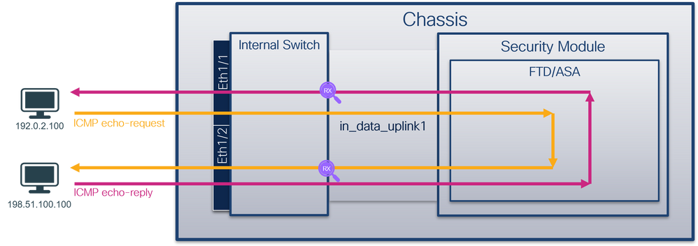
Secure Firewall 4200:
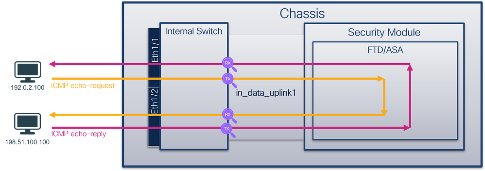
Configuration
Perform these steps on ASA or FTD CLI to configure a packet capture on interface in_data_uplink1:
- Create a capture session:
> capture capsw switch interface in_data_uplink1
The Secure Firewall 4200 supports capture directionality:
> capture capsw switch interface in_data_uplink1 direction ?
  both To capture switch bi-directional traffic
  egress To capture switch egressing traffic
  ingress To capture switch ingressing traffic

> capture capsw switch interface in_data_uplink1 direction both
2.Enable the capture session:
> no capture capsw switch stop
Verification
Verify the capture session name, administrative and operational state, interface slot, and identifier. Ensure the Pcapsize value in bytes increases and the number of captured packets is non-zero:
>  show capture capsw detail
Packet Capture info
  Name:              capsw
  Session:           1
  Admin State:       enabled
  Oper State:        up
  Oper State Reason: Active
  Config Success:    yes
  Config Fail Reason:
  Append Flag:       overwrite
  Session Mem Usage: 256
  Session Pcap Snap Len: 1518
  Error Code:        0
  Drop Count:        0

Total Physical ports involved in Packet Capture: 1

Physical port:
  Slot Id:           1
  Port Id:           18
  Pcapfile:          /mnt/disk0/packet-capture/sess-1-capsw-data-uplink1.pcap
  Pcapsize:          7704
  Filter:            capsw-1-18

Packet Capture Filter Info
  Name:              capsw-1-18
  Protocol:          0
  Ivlan:             0
  Ovlan:             0
  Src Ip:            0.0.0.0
  Dest Ip:           0.0.0.0
  Src Ipv6:          ::
  Dest Ipv6:         ::
  Src MAC:           00:00:00:00:00:00
  Dest MAC:          00:00:00:00:00:00
  Src Port:          0
  Dest Port:         0
  Ethertype:         0

Total Physical breakout ports involved in Packet Capture: 0

66 packets captured on disk using switch capture

Reading of capture file from disk is not supported
In this case, a capture is created on the interface with an internal ID 18 which is the in_data_uplink1 interface on the Secure Firewall 3130. The show portmanager switch status command in the FXOS local-mgmt command shell shows the interface IDs:
> connect fxos
…
firewall# connect local-mgmt
firewall(local-mgmt)# show portmanager switch status
Dev/Port         Mode        Link   Speed  Duplex  Loopback Mode  Port Manager
---------  ----------------  -----  -----  ------  -------------  ------------
0/1             SGMII         Up     1G     Full    None           Link-Up
0/2             SGMII         Up     1G     Full    None           Link-Up
0/3             SGMII         Up     1G     Full    None           Link-Up
0/4             SGMII         Up     1G     Full    None           Link-Up
0/5             SGMII        Down    1G     Half    None           Mac-Link-Down
0/6             SGMII        Down    1G     Half    None           Mac-Link-Down
0/7             SGMII        Down    1G     Half    None           Mac-Link-Down
0/8             SGMII        Down    1G     Half    None           Mac-Link-Down
0/9           1000_BaseX     Down    1G     Full    None           Link-Down
0/10          1000_BaseX     Down    1G     Full    None           Link-Down
0/11          1000_BaseX     Down    1G     Full    None           Link-Down
0/12          1000_BaseX     Down    1G     Full    None           Link-Down
0/13          1000_BaseX     Down    1G     Full    None           Link-Down
0/14          1000_BaseX     Down    1G     Full    None           Link-Down
0/15          1000_BaseX     Down    1G     Full    None           Link-Down
0/16          1000_BaseX     Down    1G     Full    None           Link-Down
0/17          1000_BaseX      Up     1G     Full    None           Link-Up
0/18             KR2          Up     50G    Full    None           Link-Up
0/19              KR          Up     25G    Full    None           Link-Up
0/20              KR          Up     25G    Full    None           Link-Up
0/21             KR4         Down    40G    Full    None           Link-Down
0/22             n/a         Down    n/a    Full    N/A            Reset
0/23             n/a         Down    n/a    Full    N/A            Reset
0/24             n/a         Down    n/a    Full    N/A            Reset
0/25          1000_BaseX     Down    1G     Full    None           Link-Down
0/26             n/a         Down    n/a    Full    N/A            Reset
0/27             n/a         Down    n/a    Full    N/A            Reset
0/28             n/a         Down    n/a    Full    N/A            Reset
0/29          1000_BaseX     Down    1G     Full    None           Link-Down
0/30             n/a         Down    n/a    Full    N/A            Reset
0/31             n/a         Down    n/a    Full    N/A            Reset
0/32             n/a         Down    n/a    Full    N/A            Reset
0/33          1000_BaseX     Down    1G     Full    None           Link-Down
0/34             n/a         Down    n/a    Full    N/A            Reset
0/35             n/a         Down    n/a    Full    N/A            Reset
0/36             n/a         Down    n/a    Full    N/A            Reset
To access the FXOS on ASA, run the connect fxos admin command. In the case of multi-context, run this command in the admin context.
Collect capture files
Perform the steps in the section Collect Secure Firewall Internal Switch Capture Files.
Capture file analysis
Use a packet capture file reader application to open the capture files for interface in_data_uplink1. In this example, the packets capture on the Secure Firewall 3100 are analyzed.
Check the key point - in this case, ICMP echo request and echo reply packets are captured. These are the packets sent from the application to the internal switch.
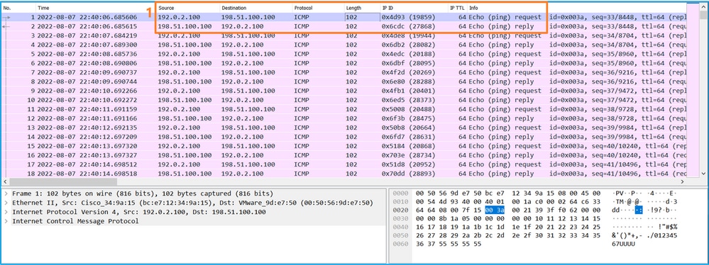
Explanation
When a switch capture on the uplink interface is configured, only packets sent from the application to the internal switch are captured. Packets sent to the application are not captured.
This table summarizes the task:
|
Task |
Capture point |
Internal filter |
Direction |
Captured traffic |
|
Configure and verify a packet capture on the uplink interface in_data_uplink1 |
in_data_uplink1 |
None |
Ingress only* |
ICMP echo requests from host 192.0.2.100 to host 198.51.100.100 ICMP echo replies from host 198.51.100.100 to host 192.0.2.100 |
* Unlike 3100, the Secure Firewall 4200 supports bidirectional (ingress and egress) captures.
Task 2
Use the FTD or ASA CLI to configure and verify a packet capture on the uplink interface in_mgmt_uplink1. Only the packets of management plane connections are captured.
Topology, packet flow, and the capture points
Secure Firewall 3100:
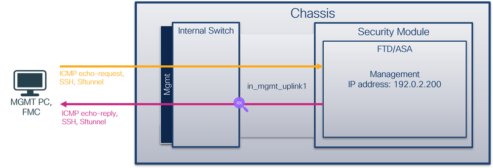
Secure Firewall 4200:

Configuration
Perform these steps on ASA or FTD CLI to configure a packet capture on interface in_mgmt_uplink1:
- Create a capture session:
> capture capsw switch interface in_mgmt_uplink1
The Secure Firewall 4200 supports capture directionality:
> capture capsw switch interface in_mgmt_uplink1 direction ?
  both To capture switch bi-directional traffic
  egress To capture switch egressing traffic
  ingress To capture switch ingressing traffic

> capture capsw switch interface in_mgmt_uplink1 direction both
2. Enable the capture session:
> no capture capsw switch stop
Verification
Verify the capture session name, administrative and operational state, interface slot, and identifier. Ensure the Pcapsize value in bytes increases and the number of captured packets is non-zero:
> show capture capsw detail
Packet Capture info
  Name:              capsw
  Session:           1
  Admin State:       enabled
  Oper State:        up
  Oper State Reason: Active
  Config Success:    yes
  Config Fail Reason:
  Append Flag:       overwrite
  Session Mem Usage: 256
  Session Pcap Snap Len: 1518
  Error Code:        0
  Drop Count:        0

Total Physical ports involved in Packet Capture: 1

Physical port:
  Slot Id:           1
  Port Id:           19
  Pcapfile:          /mnt/disk0/packet-capture/sess-1-capsw-mgmt-uplink1.pcap
  Pcapsize:          137248
  Filter:            capsw-1-19

Packet Capture Filter Info
  Name:              capsw-1-19
  Protocol:          0
  Ivlan:             0
  Ovlan:             0
  Src Ip:            0.0.0.0
  Dest Ip:           0.0.0.0
  Src Ipv6:          ::
  Dest Ipv6:         ::
  Src MAC:           00:00:00:00:00:00
  Dest MAC:          00:00:00:00:00:00
  Src Port:          0
  Dest Port:         0
  Ethertype:         0

Total Physical breakout ports involved in Packet Capture: 0

281 packets captured on disk using switch capture

Reading of capture file from disk is not supported
In this case, a capture is created on the interface with an internal ID 19 which is the in_mgmt_uplink1 interface on the Secure Firewall 3130. The show portmanager switch status command in the FXOS local-mgmt command shell shows the interface IDs:
> connect fxos
…
firewall# connect local-mgmt
firewall(local-mgmt)# show portmanager switch status
Dev/Port         Mode        Link   Speed  Duplex  Loopback Mode  Port Manager
---------  ----------------  -----  -----  ------  -------------  ------------
0/1             SGMII         Up     1G     Full    None           Link-Up
0/2             SGMII         Up     1G     Full    None           Link-Up
0/3             SGMII         Up     1G     Full    None           Link-Up
0/4             SGMII         Up     1G     Full    None           Link-Up
0/5             SGMII        Down    1G     Half    None           Mac-Link-Down
0/6             SGMII        Down    1G     Half    None           Mac-Link-Down
0/7             SGMII        Down    1G     Half    None           Mac-Link-Down
0/8             SGMII        Down    1G     Half    None           Mac-Link-Down
0/9           1000_BaseX     Down    1G     Full    None           Link-Down
0/10          1000_BaseX     Down    1G     Full    None           Link-Down
0/11          1000_BaseX     Down    1G     Full    None           Link-Down
0/12          1000_BaseX     Down    1G     Full    None           Link-Down
0/13          1000_BaseX     Down    1G     Full    None           Link-Down
0/14          1000_BaseX     Down    1G     Full    None           Link-Down
0/15          1000_BaseX     Down    1G     Full    None           Link-Down
0/16          1000_BaseX     Down    1G     Full    None           Link-Down
0/17          1000_BaseX      Up     1G     Full    None           Link-Up
0/18             KR2          Up     50G    Full    None           Link-Up
0/19              KR          Up     25G    Full    None           Link-Up
0/20              KR          Up     25G    Full    None           Link-Up
0/21             KR4         Down    40G    Full    None           Link-Down
0/22             n/a         Down    n/a    Full    N/A            Reset
0/23             n/a         Down    n/a    Full    N/A            Reset
0/24             n/a         Down    n/a    Full    N/A            Reset
0/25          1000_BaseX     Down    1G     Full    None           Link-Down
0/26             n/a         Down    n/a    Full    N/A            Reset
0/27             n/a         Down    n/a    Full    N/A            Reset
0/28             n/a         Down    n/a    Full    N/A            Reset
0/29          1000_BaseX     Down    1G     Full    None           Link-Down
0/30             n/a         Down    n/a    Full    N/A            Reset
0/31             n/a         Down    n/a    Full    N/A            Reset
0/32             n/a         Down    n/a    Full    N/A            Reset
0/33          1000_BaseX     Down    1G     Full    None           Link-Down
0/34             n/a         Down    n/a    Full    N/A            Reset
0/35             n/a         Down    n/a    Full    N/A            Reset
0/36             n/a         Down    n/a    Full    N/A            Reset
To access the FXOS on ASA, run the connect fxos admin command. In the case of multi-context, run this command in the admin context.
Collect capture files
Perform the steps in the section Collect Secure Firewall Internal Switch Capture Files.
Capture file analysis
Use a packet capture file reader application to open the capture files for interface in_mgmt_uplink1. In this example, the packets capture on the Secure Firewall 3100 are analyzed.
Check the key point - in this case only the packets from the management IP address 192.0.2.200 are shown. Examples are SSH, Sftunnel or ICMP echo reply packets. These are the packets sent from the application management interface to the network through the internal switch.
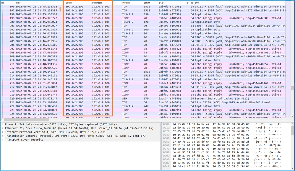
Explanation
When a switch capture on the management uplink interface is configured, only ingress packets sent from the application management interface are captured. Packets destined for the application management interface are not captured.
This table summarizes the task:
|
Task |
Capture point |
Internal filter |
Direction |
Captured traffic |
|
Configure and verify a packet capture on the management uplink interface |
in_mgmt_uplink1 |
None |
Ingress only* (from the management interface to the network through the internal switch) |
ICMP echo replies from FTD management IP address 192.0.2.200 to host 192.0.2.100 Sftunnel from FTD management IP address 192.0.2.200 to FMC IP address 192.0.2.101 SSH from FTD management IP address 192.0.2.200 to host 192.0.2.100 |
* Unlike 3100, the Secure Firewall 4200 supports bidirectional (ingress and egress) captures.
Packet Capture Filters
Internal switch packet capture filters are configured the same way as the data plane captures. Use the ethernet-type and match options to configure filters.
Configuration
Perform these steps on ASA or FTD CLI to configure a packet capture with a filter that matches ARP frames or ICMP packets from host 198.51.100.100 on interface Ethernet1/1:
- Verify the nameif:
> show nameif
Interface                Name                     Security
Ethernet1/1              inside                     0
Ethernet1/2              outside                    0
Management1/1            diagnostic                 0
- Create a capture session for ARP or ICMP:
> capture capsw switch interface inside ethernet-type arp
> capture capsw switch interface inside match icmp 198.51.100.100
Verification
Verify the capture session name and the filter. The Ethertype value is 2054 in decimal and 0x0806 in hexadecimal:
> show capture capsw detail
Packet Capture info
 Name:              capsw
  Session:           1
  Admin State:       disabled
  Oper State:        down
  Oper State Reason: Session_Admin_Shut
  Config Success:    yes
  Config Fail Reason:
  Append Flag:       overwrite
  Session Mem Usage: 256
  Session Pcap Snap Len: 1518
  Error Code:        0
  Drop Count:        0

Total Physical ports involved in Packet Capture: 1

Physical port:
  Slot Id:           1
  Port Id:           1
  Pcapfile:          /mnt/disk0/packet-capture/sess-1-capsw-ethernet-1-1-0.pcap
  Pcapsize:          0
  Filter:            capsw-1-1

Packet Capture Filter Info
  Name:              capsw-1-1
  Protocol:          0
  Ivlan:             0
  Ovlan:             0
  Src Ip:            0.0.0.0
  Dest Ip:           0.0.0.0
  Src Ipv6:          ::
  Dest Ipv6:         ::
  Src MAC:           00:00:00:00:00:00
  Dest MAC:          00:00:00:00:00:00
  Src Port:          0
  Dest Port:         0
  Ethertype:         2054

Total Physical breakout ports involved in Packet Capture: 0

0 packet captured on disk using switch capture

Reading of capture file from disk is not supported
This is the verification of the filter for ICMP. IP protocol 1 is the ICMP:
> show capture capsw detail
Packet Capture info
  Name:              capsw
  Session:           1
  Admin State:       disabled
  Oper State:        down
  Oper State Reason: Session_Admin_Shut
  Config Success:    yes
  Config Fail Reason:
  Append Flag:       overwrite
  Session Mem Usage: 256
  Session Pcap Snap Len: 1518
  Error Code:        0
  Drop Count:        0

Total Physical ports involved in Packet Capture: 1

Physical port:
  Slot Id:           1
  Port Id:           1
  Pcapfile:          /mnt/disk0/packet-capture/sess-1-capsw-ethernet-1-1-0.pcap
  Pcapsize:          0
  Filter:            capsw-1-1

Packet Capture Filter Info
  Name:              capsw-1-1
  Protocol:          1
  Ivlan:             0
  Ovlan:             0
  Src Ip:            198.51.100.100
  Dest Ip:           0.0.0.0
  Src Ipv6:          ::
  Dest Ipv6:         ::
  Src MAC:           00:00:00:00:00:00
  Dest MAC:          00:00:00:00:00:00
  Src Port:          0
  Dest Port:         0
  Ethertype:         0

Total Physical breakout ports involved in Packet Capture: 0

0 packets captured on disk using switch capture

Reading of capture file from disk is not supported
Collect Secure Firewall Internal Switch Capture Files
Use ASA or FTD CLI to collect internal switch capture files. On FTD, the capture file can also be exported via the CLI copy command to destinations reachable via the data or diagnostic interfaces.
Alternatively, the file can be copied to /ngfw/var/common in expert mode and downloaded from FMC via the File Download option.
In the case of port-channel interfaces ensure to collect packet capture files from all member interfaces.
ASA
Perform these steps on to collect internal switch capture files on ASA CLI:
- Stop the capture:
asa# capture capsw switch stop
- Verify the capture session is stopped and note the capture file name.
asa# show capture capsw detail
Packet Capture info
  Name:              capsw
  Session:           1
  Admin State:       disabled
  Oper State:        down
  Oper State Reason: Session_Admin_Shut
  Config Success:    yes
  Config Fail Reason:
  Append Flag:       overwrite
  Session Mem Usage: 256
  Session Pcap Snap Len: 1518
  Error Code:        0
  Drop Count:        0

Total Physical ports involved in Packet Capture: 1

Physical port:
  Slot Id:           1
  Port Id:           1
  Pcapfile:          /mnt/disk0/packet-capture/sess-1-capsw-ethernet-1-1-0.pcap
  Pcapsize:          139826
  Filter:            capsw-1-1

Packet Capture Filter Info
  Name:              capsw-1-1
  Protocol:          0
  Ivlan:             0
  Ovlan:             0
  Src Ip:            0.0.0.0
  Dest Ip:           0.0.0.0
  Src Ipv6:          ::
  Dest Ipv6:         ::
  Src MAC:           00:00:00:00:00:00
  Dest MAC:          00:00:00:00:00:00
  Src Port:          0
  Dest Port:         0
  Ethertype:         0

Total Physical breakout ports involved in Packet Capture: 0

886 packets captured on disk using switch capture

Reading of capture file from disk is not supported
-
Use the CLI copy command to export the file to remote destinations:
asa# copy flash:/packet-capture/sess-1-capsw-ethernet-1-1-0.pcap ?
  cluster:        Copy to cluster: file system
  disk0:          Copy to disk0: file system
  disk1:          Copy to disk1: file system
  flash:          Copy to flash: file system
  ftp:            Copy to ftp: file system
  running-config  Update (merge with) current system configuration
  scp:            Copy to scp: file system
  smb:            Copy to smb: file system
  startup-config  Copy to startup configuration
  system:         Copy to system: file system
  tftp:           Copy to tftp: file system

asa# copy flash:/packet-capture/sess-1-capsw-ethernet-1-1-0.pcap tftp://198.51.100.10/
Source filename [/packet-capture/sess-1-capsw-ethernet-1-1-0.pcap]?
Destination filename [sess-1-capsw-ethernet-1-1-0.pcap]?
Copy in progress...C
139826 bytes copied in 0.532 secs
FTD
Perform these steps to collect internal switch capture files on FTD CLI and copy them to servers reachable via data or diagnostic interfaces:
- Go to diagnostic CLI:
> system support diagnostic-cli
Attaching to Diagnostic CLI ... Click 'Ctrl+a then d' to detach.
Type help or '?' for a list of available commands.

firepower> enable
Password: <-- Enter
firepower#
- Stop the capture:
firepower# capture capi switch stop
- Verify the capture session is stopped and note the capture file name:
firepower# show capture capsw detail
Packet Capture info
  Name:              capsw
  Session:           1
  Admin State:       disabled
  Oper State:        down
  Oper State Reason: Session_Admin_Shut
  Config Success:    yes
  Config Fail Reason:
  Append Flag:       overwrite
  Session Mem Usage: 256
  Session Pcap Snap Len: 1518
  Error Code:        0
  Drop Count:        0

Total Physical ports involved in Packet Capture: 1
Physical port:
  Slot Id:           1
  Port Id:           1
  Pcapfile:          /mnt/disk0/packet-capture/sess-1-capsw-ethernet-1-1-0.pcap
  Pcapsize:          139826
  Filter:            capsw-1-1

Packet Capture Filter Info
  Name:              capsw-1-1
  Protocol:          0
  Ivlan:             0
  Ovlan:             0
  Src Ip:            0.0.0.0
  Dest Ip:           0.0.0.0
  Src Ipv6:          ::
  Dest Ipv6:         ::
  Src MAC:           00:00:00:00:00:00
  Dest MAC:          00:00:00:00:00:00
  Src Port:          0
  Dest Port:         0
  Ethertype:         0

Total Physical breakout ports involved in Packet Capture: 0

886 packets captured on disk using switch capture

Reading of capture file from disk is not supported
- Use the CLI copy command to export the file to remote destinations.
firepower# copy flash:/packet-capture/sess-1-capsw-ethernet-1-1-0.pcap ?
  cluster:        Copy to cluster: file system
  disk0:          Copy to disk0: file system
  disk1:          Copy to disk1: file system
  flash:          Copy to flash: file system
  ftp:            Copy to ftp: file system
  running-config  Update (merge with) current system configuration
  scp:            Copy to scp: file system
  smb:            Copy to smb: file system
  startup-config  Copy to startup configuration
  system:         Copy to system: file system
  tftp:           Copy to tftp: file system

firepower# copy flash:/packet-capture/sess-1-capsw-ethernet-1-1-0.pcap tftp://198.51.100.10/
Source filename [/packet-capture/sess-1-capsw-ethernet-1-1-0.pcap]?
Destination filename [sess-1-capsw-ethernet-1-1-0.pcap]?
Copy in progress...C
139826 bytes copied in 0.532 secs
Perform these steps on to collect capture files from FMC via the File Download option:
- Stop the capture:
> capture capsw switch stop
- Verify the capture session is stopped and note the file name and full capture file path:
> show capture capsw detail
Packet Capture info
  Name:              capsw
  Session:           1
  Admin State:       disabled
  Oper State:        down
  Oper State Reason: Session_Admin_Shut
  Config Success:    yes
  Config Fail Reason:
  Append Flag:       overwrite
  Session Mem Usage: 256
  Session Pcap Snap Len: 1518
  Error Code:        0
  Drop Count:        0

Total Physical ports involved in Packet Capture: 1

Physical port:
  Slot Id:           1
  Port Id:           1
  Pcapfile:          /mnt/disk0/packet-capture/sess-1-capsw-ethernet-1-1-0.pcap
  Pcapsize:          139826
  Filter:            capsw-1-1

Packet Capture Filter Info
  Name:              capsw-1-1
  Protocol:          0
  Ivlan:             0
  Ovlan:             0
  Src Ip:            0.0.0.0
  Dest Ip:           0.0.0.0
  Src Ipv6:          ::
  Dest Ipv6:         ::
  Src MAC:           00:00:00:00:00:00
  Dest MAC:          00:00:00:00:00:00
  Src Port:          0
  Dest Port:         0
  Ethertype:         0

Total Physical breakout ports involved in Packet Capture: 0
886 packets captured on disk using switch capture
Reading of capture file from disk is not supported
- Go to expert mode and switch to root mode:
> expert
admin@firepower:~$ sudo su
root@firepower:/home/admin
- Copy the capture file to /ngfw/var/common/:
root@KSEC-FPR3100-1:/home/admin cp /mnt/disk0/packet-capture/sess-1-capsw-ethernet-1-1-0.pcap /ngfw/var/common/
root@KSEC-FPR3100-1:/home/admin ls -l /ngfw/var/common/sess*
-rwxr-xr-x 1 root admin 139826 Aug  7 20:14 /ngfw/var/common/sess-1-capsw-ethernet-1-1-0.pcap
-rwxr-xr-x 1 root admin     24 Aug  6 21:58 /ngfw/var/common/sess-1-capsw-ethernet-1-3-0.pcap
- On FMC choose Devices > File Download:
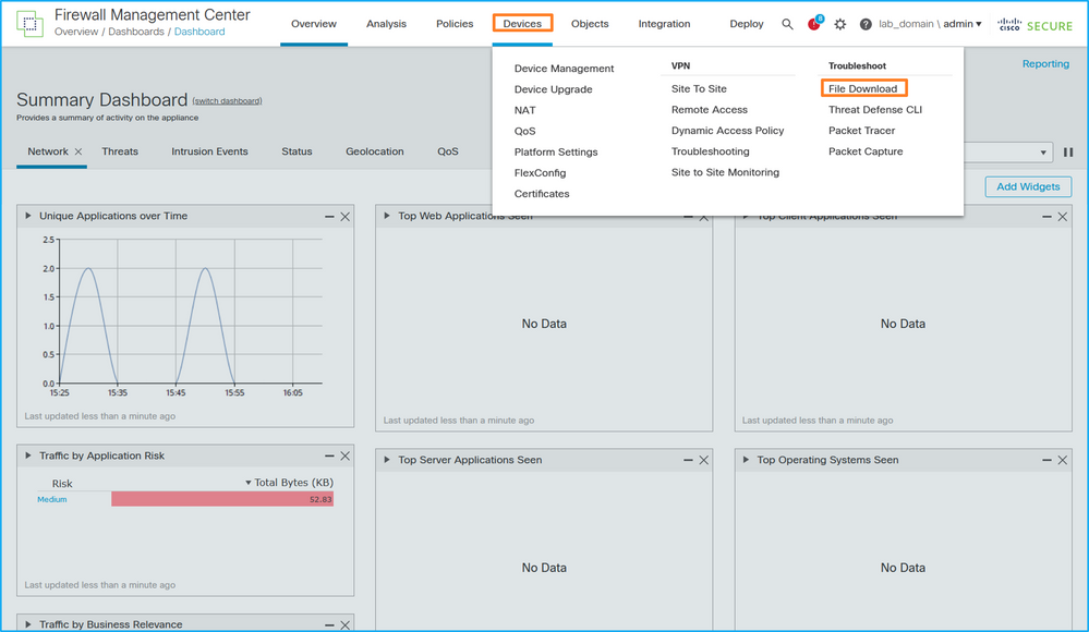
- Choose the FTD, provide the capture file name, and click Download:

Guidelines, Limitations, and Best Practices for Internal Switch Packet Capture
Guidelines and limitations:
- Multiple switch capture configuration sessions are supported, but only 1 switch capture session can be active at a time. An attempt to enable 2 or more capture sessions results in an error "ERROR: Failed to enable session, as limit of maximum 1 active packet capture sessions reached".
- An active switch capture cannot be deleted.
- Switch captures cannot be read on the application. The user must export the files.
- Certain data plane capture options such as dump, decode, packet-number, trace, and others are not supported for switch captures.
-
In the case of multi-context ASA, the switch captures on data interfaces are configured in user contexts. The switch captures on interfaces in_data_uplink1, and in_mgmt_uplink1 are supported only in the admin context.
This is the list of best practices based on the usage of packet capture in TAC cases:
- Be aware of guidelines and limitations.
- Use capture filters.
- Consider the impact of NAT on packet IP addresses when a capture filter is configured.
- Increase or decrease the packet-length that specifies frame size, in case it differs from the default value of 1518 bytes. Shorter size results in an increased number of captured packets and vice versa.
- Adjust the buffer size as needed.
- Be aware of the Drop Count in the output of the show cap <cap_name> detail command. Once the buffer size limit is reached, the drop count counter increases.
Related Information
Revision History
| Revision | Publish Date | Comments |
|---|---|---|
2.0 |
17-Sep-2022 |
Initial Release |
1.0 |
27-Aug-2022 |
Initial Release |
Contributed by Cisco Engineers
- Ilkin GasimovCisco TAC Engineer
- Mikis ZafeiroudisCisco TAC Engineer
Contact Cisco
- Open a Support Case

- (Requires a Cisco Service Contract)
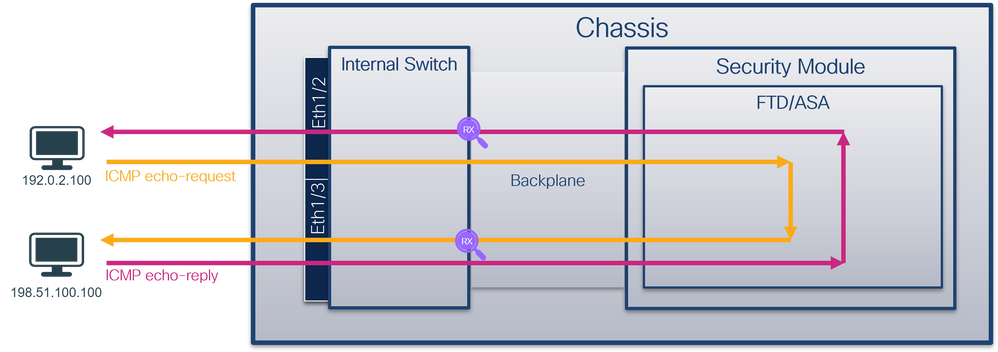
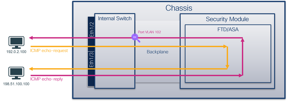
 Feedback