FlexVPN: IPv6 in a Hub and Spoke Deployment Configuration Example
Available Languages
Contents
Introduction
This document describes a common configuration that uses a Cisco IOS® FlexVPN spoke and hub deployment in an IPv6 environment. It expands on the concepts discussed in FlexVPN: IPv6 Basic LAN to LAN Configuration.
Prerequisites
Requirements
Cisco recommends that you have knowledge of these topics:
- Cisco IOS FlexVPN
- Routing protocols
Components Used
The information in this document is based on these software and hardware versions:
- Cisco Integrated Services Routers Generation 2 (ISR G2)
- Cisco IOS Software Release 15.3 (or Release 15.4T for dynamic spoke-to-spoke tunnels with IPv6)
The information in this document was created from the devices in a specific lab environment. All of the devices used in this document started with a cleared (default) configuration. If your network is live, make sure that you understand the potential impact of any command.
Configure
While this configuration example and network diagram use IPv6 as the transport network, Generic Routing Encapsulation (GRE) is typically used in FlexVPN deployments. Use of GRE instead of IPsec allows administrators to run IPv4 or IPv6 or both over the same tunnels, regardless of the transport network.
Network Diagram
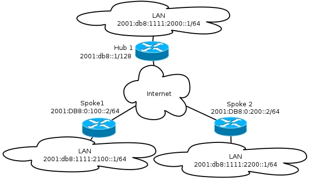
Transport Network
This is a diagram of the transport network used in this example:

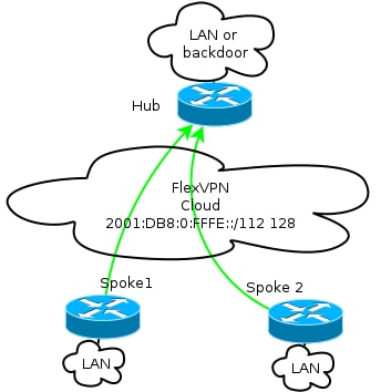
Overlay Network
This is a diagram of the basic overlay network topology used in this example:

Every spoke is assigned from a pool of addresses of /112, but receives a /128 address. Thus, the notation '/112 128' is used in IPv6 pool configuration of the hub.
Configurations
This configuration shows an IPv4 and IPv6 overlay that works over an IPv6 backbone.
When compared to examples that use IPv4 as a backbone, note that you should use the tunnel mode command in order to node change and accommodate IPv6 transport.
The spoke-to-spoke tunnel feature over IPv6 will be introduced in Cisco IOS Software Release 15.4T, which is not yet available.
Routing Protocols
Cisco recommends that you use internal Border Gateway Protocol (iBGP) for peering between spoke and hubs for large deployments because iBGP is the most scalable routing protocol.
The Border Gateway Protocol (BGP) listen range does not support IPv6 range, but it does simplify usage with an IPv4 transport. Although it is feasible to use BGP in such an environment, this configuration illustrates a basic example, so the Enhanced Interior Gateway Routing Protocol (EIGRP) was chosen.
Hub Configuration
Compared to older examples, this configuration includes the use of new transport protocols.
In order to configure the hub, the administrator needs to:
- Enable unicast routing.
- Provision transport routing.
- Provision a new pool of IPv6 addresses to be assigned dynamically. The pool is 2001:DB8:0:FFFE::/112; 16 bits allows for 65,535 devices to be addressed.
- Enable IPv6 for the Next Hop Resolution Protocol (NHRP) configuration in order to allow IPv6 in the overlay.
- Account for IPv6 addressing in the keyring as well as the profile in the crypto configuration.
In this example, the hub advertises an EIGRP summary to all the spokes.
Cisco does not recommend use of a summary address on the Virtual-Template interface in FlexVPN deployment; however, in a Dynamic Multipoint VPN (DMVPN), this is not only common but is also considered a best practice. See FlexVPN Migration: Hard Move from DMVPN to FlexVPN on Same Devices: Updated hub configuration for details.
ipv6 unicast-routing
ipv6 cef

ip local pool FlexSpokes 10.1.1.176 10.1.1.254
ipv6 local pool FlexSpokesv6 2001:DB8:0:FFFE::/112 128

crypto ikev2 authorization policy default
 ipv6 pool FlexSpokesv6
 pool FlexSpokes
 route set interface
crypto ikev2 keyring Flex_key
 peer ALL
 address ::/0
 pre-shared-key local cisco
 pre-shared-key remote cisco
 !
crypto ikev2 profile Flex_IKEv2
 match identity remote address ::/0
 authentication remote pre-share
 authentication local pre-share
 keyring local Flex_key
 aaa authorization group psk list default default
 virtual-template 1

crypto ikev2 dpd 30 5 on-demand

interface Virtual-Template1 type tunnel
 ip unnumbered Loopback100
 ip mtu 1400
 ip nhrp network-id 2
 ip nhrp redirect
 ip tcp adjust-mss 1360
 ipv6 mtu 1400
 ipv6 tcp adjust-mss 1358
 ipv6 unnumbered Loopback100
 ipv6 enable
 ipv6 eigrp 65001
 ipv6 nhrp network-id 2
 ipv6 nhrp redirect
 tunnel mode gre ipv6
 tunnel protection ipsec profile default

interface Ethernet1/0
 description LAN subnet
 ip address 192.168.0.1 255.255.255.0
 ipv6 address 2001:DB8:1111:2000::1/64
 ipv6 enable
 ipv6 eigrp 65001

interface Loopback0
 ip address 172.25.1.1 255.255.255.255
 ipv6 address 2001:DB8::1/128
 ipv6 enable

ip route 192.168.0.0 255.255.0.0 Null0
ipv6 route 2001:DB8:1111::/48 Null0

ip prefix-list EIGRP_SUMMARY_ONLY seq 5 permit 192.168.0.0/16
ipv6 prefix-list EIGRP_SUMMARY_v6 seq 5 permit 2001:DB8:1111::/48

router eigrp 65001
 distribute-list prefix EIGRP_SUMMARY_ONLY out Virtual-Template1
 network 10.1.1.0 0.0.0.255
 network 192.168.0.0 0.0.255.255
 redistribute static metric 1500 10 10 1 1500

ipv6 router eigrp 65001
 distribute-list prefix-list EIGRP_SUMMARY_v6 out Virtual-Template1
 redistribute static metric 1500 10 10 1 1500
Spoke Configuration
As in the hub configuration, the administrator needs to provision IPv6 addressing, enable IPv6 routing, and add NHRP and crypto configuration.
It is feasible to use EIGRP and other routing protocols for spoke-to-spoke peering. However, in a typical scenario, the protocols are not needed and might impact scalability and stability.
In this example, the routing configuration keeps only EIGRP adjacency between the spoke and the hub, and the only interface that is not passive is the Tunnel1 interface:
ipv6 unicast-routing
ipv6 cef

crypto logging session

crypto ikev2 authorization policy default
 route set interface
crypto ikev2 keyring Flex_key
 peer ALL
 address ::/0
 pre-shared-key local cisco
 pre-shared-key remote cisco
 !
crypto ikev2 profile Flex_IKEv2
 match identity remote address ::/0
 authentication remote pre-share
 authentication local pre-share
 keyring local Flex_key
 aaa authorization group psk list default default
 virtual-template 1

crypto ikev2 dpd 30 5 on-demand

interface Tunnel1
 description FlexVPN tunnel
 ip address negotiated
 ip mtu 1400
 ip nhrp network-id 2
 ip nhrp shortcut virtual-template 1
 ip nhrp redirect
 ip tcp adjust-mss 1360
 delay 1000
 ipv6 mtu 1400
 ipv6 tcp adjust-mss 1358
 ipv6 address negotiated
 ipv6 enable
 ipv6 nhrp network-id 2
 ipv6 nhrp shortcut virtual-template 1
 ipv6 nhrp redirect
 tunnel source Ethernet0/0
 tunnel mode gre ipv6
 tunnel destination 2001:DB8::1
 tunnel protection ipsec profile default

interface Virtual-Template1 type tunnel
 ip unnumbered Ethernet1/0
 ip mtu 1400
 ip nhrp network-id 2
 ip nhrp shortcut virtual-template 1
 ip nhrp redirect
 ip tcp adjust-mss 1360
 delay 1000
 ipv6 mtu 1400
 ipv6 tcp adjust-mss 1358
 ipv6 unnumbered Ethernet1/0
 ipv6 enable
 ipv6 nhrp network-id 2
 ipv6 nhrp shortcut virtual-template 1
 ipv6 nhrp redirect
 tunnel mode gre ipv6
 tunnel protection ipsec profile default
Follow these recommendations when you create routing protocol entries on a spoke:
- Allow the routing protocol to establish a relationship via the connection (in this case, the Tunnel1 interface) to the hub. It is generally not desirable to establish routing adjacency between spokes because this significantly increases complexity in most cases.
- Advertise local LAN subnet(s) only, and enable the routing protocol on an IP address assigned by the hub. Be careful not to advertise a large subnet because it might impact spoke-to-spoke communication.
This example reflects both recommendations for EIGRP on Spoke1:
router eigrp 65001
 network 10.1.1.0 0.0.0.255
 network 192.168.101.0 0.0.0.255
 passive-interface default
 no passive-interface Tunnel1

ipv6 router eigrp 65001
 passive-interface default
 no passive-interface Tunnel1
Verify
Use this section to confirm that your configuration works properly.
Spoke-to-Hub Session
A properly configured session between spoke and hub devices has an Internet Key Exchange Version 2 (IKEv2) session that is up and has a routing protocol that can establish adjacency. In this example, the routing protocol is EIGRP, so there are two EIGRP commands:
- show crypto ikev2 sa
- show ipv6 eigrp 65001 neighbor
- show ip eigrp 65001 neighbor
Spoke1#show crypto ikev2 sa
 IPv4 Crypto IKEv2  SA

 IPv6 Crypto IKEv2  SA

Tunnel-id    fvrf/ivrf              Status
1          none/none             READY
Local  2001:DB8:0:100::2/500
Remote  2001:DB8::1/500
      Encr: AES-CBC, keysize: 256, Hash: SHA512, DH Grp:5, Auth sign: PSK, Auth
         verify: PSK
      Life/Active Time: 86400/1945 sec

Spoke1#sh ipv6 eigrp 65001 neighbor
EIGRP-IPv6 Neighbors for AS(65001)
H   Address                 Interface          Hold Uptime   SRTT   RTO  Q  Seq
                                               (sec)         (ms)       Cnt Num
0   Link-local address:     Tu1                  14 00:32:29   72  1470  0  10
    FE80::A8BB:CCFF:FE00:6600

Spoke1#show ip eigrp neighbors
EIGRP-IPv4 Neighbors for AS(65001)
H   Address                 Interface          Hold Uptime   SRTT   RTO  Q  Seq
                                               (sec)         (ms)       Cnt Num
0   10.1.1.1                Tu1                  11 00:21:05   11  1398  0  26
In IPv4, EIGRP uses an assigned IP address to peer; in the previous example, it is the hub IP address of 10.1.1.1.
IPv6 uses a link-local address; in this example, the hub is FE80::A8BB:CCFF:FE00:6600. Use the ping command in order to verify that the hub can be reached through its link-local IP:
Spoke1#ping FE80::A8BB:CCFF:FE00:6600
Output Interface: tunnel1
Type escape sequence to abort.
Sending 5, 100-byte ICMP Echos to FE80::A8BB:CCFF:FE00:6600, timeout is
   2 seconds:
Packet sent with a source address of FE80::A8BB:CCFF:FE00:6400%Tunnel1
!!!!!
Success rate is 100 percent (5/5), round-trip min/avg/max = 5/5/5 ms
Spoke-to-Spoke Session
Spoke-to-spoke sessions are brought up dynamically on demand. Use a simple ping command in order to trigger a session:
Spoke1#ping  2001:DB8:1111:2200::100 source e1/0
Type escape sequence to abort.
Sending 5, 100-byte ICMP Echos to 2001:DB8:1111:2200::100, timeout is 2 seconds:
Packet sent with a source address of 2001:DB8:1111:2100::1
!!!!!
Success rate is 100 percent (5/5), round-trip min/avg/max = 5/8/10 ms
To confirm direct spoke-to-spoke connectivity, the administrator needs to:
- Verify that a dynamic spoke-to-spoke session triggers a new Virtual-Access interface:
%LINEPROTO-5-UPDOWN: Line protocol on Interface Virtual-Access1, changed
   state to up
%CRYPTO-5-IKEV2_SESSION_STATUS: Crypto tunnel v2 is UP.
Peer 2001:DB8:0:200::2:500 Id: 2001:DB8:0:200::2 - Verify the IKEv2 session state:
Spoke1#show crypto ikev2 sa
Note that two sessions are available: one spoke-to-hub and one spoke-to-spoke.
IPv4 Crypto IKEv2 SA
IPv6 Crypto IKEv2 SA
Tunnel-id fvrf/ivrf Status
1 none/none READY
Local 2001:DB8:0:100::2/500
Remote 2001:DB8::1/500
Encr: AES-CBC, keysize: 256, Hash: SHA512, DH Grp:5, Auth sign: PSK,
Auth verify: PSK
Life/Active Time: 86400/3275 sec
Tunnel-id fvrf/ivrf Status
2 none/none READY
Local 2001:DB8:0:100::2/500
Remote 2001:DB8:0:200::2/500
Encr: AES-CBC, keysize: 256, Hash: SHA512, DH Grp:5, Auth sign: PSK,
Auth verify: PSK
Life/Active Time: 86400/665 sec
- Verify NHRP:
Spoke1#show ipv6 nhrp
2001:DB8:0:FFFE::/128 via 2001:DB8:0:FFFE::
 Virtual-Access1 created 00:00:10, expire 01:59:49
 Type: dynamic, Flags: router nhop rib nho
 NBMA address: 2001:DB8:0:200::2
2001:DB8:1111:2200::/64 via 2001:DB8:0:FFFE::
 Virtual-Access1 created 00:00:10, expire 01:59:49
 Type: dynamic, Flags: router rib nho
 NBMA address: 2001:DB8:0:200::2
The output shows that 2001:DB8:1111:2200::/64 (the LAN for Spoke2) is available via 2001:DB8:0:FFFE::, which is the negotiated IPv6 address on the Tunnel1 interface for Spoke2. The Tunnel1 interface is available via the nonbroadcast multiaccess (NBMA) address of 2001:db8:0:200::2 , which is the IPv6 address assigned to Spoke2 statically.
- Verify that traffic is passing via that interface:
Spoke1#sh crypto ipsec sa peer 2001:DB8:0:200::2

interface: Virtual-Access1
    Crypto map tag: Virtual-Access1-head-0, local addr 2001:DB8:0:100::2

   protected vrf: (none)
   local  ident (addr/mask/prot/port): (2001:DB8:0:100::2/128/47/0)
   remote ident (addr/mask/prot/port): (2001:DB8:0:200::2/128/47/0)
   current_peer 2001:DB8:0:200::2 port 500
     PERMIT, flags={origin_is_acl,}
    #pkts encaps: 196, #pkts encrypt: 196, #pkts digest: 196
    #pkts decaps: 195, #pkts decrypt: 195, #pkts verify: 195
(...) - Verify the routing path and CEF settings:
Spoke1#show ipv6 route
(...)
D   2001:DB8:1111:2200::/64 [90/27161600]
     via 2001:DB8:0:FFFE::, Virtual-Access1 [Shortcut]
     via FE80::A8BB:CCFF:FE00:6600, Tunnel1
(...)
Spoke1#show ipv6 cef 2001:DB8:1111:2200::
2001:DB8:1111:2200::/64
  nexthop 2001:DB8:0:FFFE:: Virtual-Access
Troubleshoot
This section provides information you can use to troubleshoot your configuration.
These debug commands help you troubleshoot issues:
- FlexVPN/IKEv2 and IPsec:
- debug crypto ipsec
- debug crypto ikev2 [packet|internal]
- NHRP (spoke-to-spoke):
- debug nhrp pack
- debug nhrp extension
- debug nhrp cache
- debug nhrp route
Refer to the Cisco IOS Master Command List, All Releases for more information on these commands.
Revision History
| Revision | Publish Date | Comments |
|---|---|---|
1.0 |
08-Oct-2013 |
Initial Release |
Contact Cisco
- Open a Support Case

- (Requires a Cisco Service Contract)
 Feedback