Introduction
This document describes the procedure to configure ZBFW with FQDN ACL pattern matching in autonomous mode on the C8300 platform.
Prerequisites
Requirements
Cisco recommends that you have knowledge of this topic:
- Zone-Based Policy Firewall (ZBFW)
- Virtual Routing and Forwarding (VRF)
- Network Address Translation (NAT)
Components Used
The information in this document is based on these software and hardware versions:
The information in this document was created from the devices in a specific lab environment. All of the devices used in this document started with a cleared (default) configuration. If your network is live, ensure that you understand the potential impact of any command.
Background Information
Zone-Based Policy Firewall (ZBFW) is an advanced method of firewall configuration on Cisco IOS® and Cisco IOS XE devices that allows for creating security zones within the network.
ZBFW allows administrators to group interfaces into zones and apply firewall policies to traffic moving between these zones.
FQDN ACLs (Fully Qualified Domain Name Access Control Lists), used with a ZBFW in Cisco routers, allow administrators to create firewall rules that match traffic based on domain names instead of only IP addresses.
This feature is particularly useful when dealing with services hosted on platforms such as AWS or Azure, where the IP address associated with a service can change frequently.
It simplifies the management of access control policies and improves the flexibility of security configurations within the network.
Configure
Network Diagram
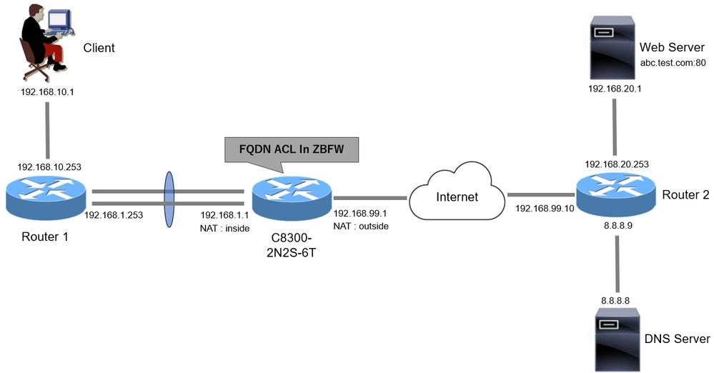
This document introduces the configuration and verification for ZBFW base on this diagram. This is a simulated environment using BlackJumboDog as a DNS server.
 Network Diagram
Configurations
This is the configuration to permit communication from the client to the web server.
Step 1. (Optional) Configure VRF
The VRF (Virtual Routing and Forwarding) feature allows you to create and manage multiple independent routing tables within a single router. In this example, we create a VRF called WebVRF and perform routing for related communications.
vrf definition WebVRF
rd 65010:10
!
address-family ipv4
route-target export 65010:10
route-target import 65010:10
exit-address-family
!
address-family ipv6
route-target export 65010:10
route-target import 65010:10
exit-address-family

ip route vrf WebVRF 8.8.8.8 255.255.255.255 GigabitEthernet0/0/3 192.168.99.10
ip route vrf WebVRF 192.168.10.0 255.255.255.0 Port-channel1.2001 192.168.1.253
ip route vrf WebVRF 192.168.20.0 255.255.255.0 GigabitEthernet0/0/3 192.168.99.10
Step 2. Configure Interface
Configure basic information such as zone-member, VRF, NAT and IP addresses for the Inside and Outside interfaces.
interface GigabitEthernet0/0/1
no ip address
negotiation auto
lacp rate fast
channel-group 1 mode active

interface GigabitEthernet0/0/2
no ip address
negotiation auto
lacp rate fast
channel-group 1 mode active

interface Port-channel1
no ip address
no negotiation auto

interface Port-channel1.2001
encapsulation dot1Q 2001
vrf forwarding WebVRF
ip address 192.168.1.1 255.255.255.0
ip broadcast-address 192.168.1.255
no ip redirects
no ip proxy-arp
ip nat inside
zone-member security zone_client

interface GigabitEthernet0/0/3
vrf forwarding WebVRF
ip address 192.168.99.1 255.255.255.0
ip nat outside
zone-member security zone_internet
speed 1000
no negotiation auto
Step 3. (Optional) Configure NAT
Configure NAT for Inside and Outside interfaces. In this example, the source IP address from the Client (192.168.10.1) is translated to 192.168.99.100.
ip access-list standard nat_source
10 permit 192.168.10.0 0.0.0.255

ip nat pool natpool 192.168.99.100 192.168.99.100 prefix-length 24
ip nat inside source list nat_source pool natpool vrf WebVRF overload
Step 4. Configure FQDN ACL
Configure FQDN ACL to match the target traffic. In this example, use the wildcard '*' in the pattern matching of the FQDN object group to match the destination FQDN.
object-group network src_net
192.168.10.0 255.255.255.0

object-group fqdn dst_test_fqdn
pattern .*\.test\.com

object-group network dst_dns
host 8.8.8.8

ip access-list extended Client-WebServer
1 permit ip object-group src_net object-group dst_dns
5 permit ip object-group src_net fqdn-group dst_test_fqdn
Step 5. Configure ZBFW
Configure zone, class-map, policy-map for ZBFW. In this example, by using parameter-map, logs is generated when the traffic is permitted by ZBFW.
zone security zone_client
zone security zone_internet

parameter-map type inspect inspect_log
audit-trail on

class-map type inspect match-any Client-WebServer-Class
match access-group name Client-WebServer

policy-map type inspect Client-WebServer-Policy
class type inspect Client-WebServer-Class
inspect inspect_log
class class-default
drop log

zone-pair security Client-WebServer-Pair source zone_client destination zone_internet
service-policy type inspect Client-WebServer-Policy
Verify
Step 1. Initiate HTTP Connection From Client
Verify that HTTP communication from the Client to the WEB server is successful.
 HTTP Connection
Step 2. Confirm IP Cache
Run show platform hardware qfp active feature dns-snoop-agent datapath ip-cache all command to confirm that the IP cache for the target FQDN is generated in C8300-2N2S-6T.
02A7382#show platform hardware qfp active feature dns-snoop-agent datapath ip-cache all
IP Address Client(s) Expire RegexId Dirty VRF ID Match
------------------------------------------------------------------------------------------------------
192.168.20.1 0x1 117 0xdbccd400 0x00 0x0 .*\.test\.com
Step 3. Confirm ZBFW Log
Confirm that the IP address (192.168.20.1) is matching to the FQDN (.*\.test\.com), and verify that the HTTP communication in step 1 is permitted by ZBFW.
*Mar 7 11:08:23.018: %IOSXE-6-PLATFORM: R0/0: cpp_cp: QFP:0.0 Thread:003 TS:00000551336606461468 %FW-6-SESS_AUDIT_TRAIL_START: (target:class)-(Client-WebServer-Pair:Client-WebServer-Class):Start http session: initiator (192.168.10.1:51468) -- responder (192.168.20.1(.*\.test\.com):80) from Port-channel1.2001

*Mar 7 11:08:24.566: %IOSXE-6-PLATFORM: R0/0: cpp_cp: QFP:0.0 Thread:002 TS:00000551338150591101 %FW-6-SESS_AUDIT_TRAIL: (target:class)-(Client-WebServer-Pair:Client-WebServer-Class):Stop http session: initiator (192.168.10.1:51468) sent 943 bytes -- responder (192.168.20.1:80) sent 101288 bytes, from Port-channel1.2001
Step 4. Confirm Packet Capture
Confirm that the DNS resolution for target FQDN and the HTTP connection between the Client and the WEB server are successful.
Packet Capture in Inside :
 DNS Packets in Inside
 HTTP Packets in Inside
Packet Capture in Onside (192.168.10.1 is NAT to 192.168.19.100) :
 DNS Packets in Outside
 HTTP Packets in Outside
Troubleshoot
For troubleshooting communication issues related to ZBFW using FQDN ACL pattern matching, you can collect the logs during the issue and provide them to Cisco TAC. Please note that the logs for troubleshooting depend on the nature of the issue.
Example of logs to be collected :
!!!! before reproduction
!! Confirm the IP cache
show platform hardware qfp active feature dns-snoop-agent datapath ip-cache all

!! Enable packet-trace
debug platform packet-trace packet 8192 fia-trace
debug platform packet-trace copy packet both
debug platform condition ipv4 access-list Client-WebServer both
debug platform condition feature fw dataplane submode all level verbose

!! Enable debug-level system logs and ZBFW debug logs
debug platform packet-trace drop
debug acl cca event
debug acl cca error
debug ip domain detail
!! Start to debug
debug platform condition start

!! Enable packet capture on the target interface (both sides) and start the capture
monitor capture CAPIN interface Port-channel1.2001 both
monitor capture CAPIN match ipv4 any any
monitor capture CAPIN buffer size 32
monitor capture CAPIN start

monitor capture CAPOUT interface g0/0/3 both
monitor capture CAPOUT match ipv4 any any
monitor capture CAPOUT buffer size 32
monitor capture CAPOUT start

!! (Optional) Clear the DNS cache on the client
ipconfig/flushdns
ipconfig /displaydns

!! Run the show command before reproduction
show platform hardware qfp active feature firewall drop all
show policy-map type inspect zone-pair Client-WebServer-Pair sessions
show platform packet-trace statistics
show platform packet-trace summary
show logging process cpp_cp internal start last boot
show platform hardware qfp active feature dns-snoop-agent client hw-pattern-list
show platform hardware qfp active feature dns-snoop-agent client info
show platform hardware qfp active feature dns-snoop-agent datapath stats
show ip dns-snoop all
show platform hardware qfp active feature dns-snoop-agent datapath ip-cache all
show platform software access-list F0 summary

!!!! Reproduce the issue - start

!! During the reproductionof the issue, run show commands at every 10 seconds
!! Skip show ip dns-snoop all command if it is not supported on the specific router
show ip dns-snoop all
show platform hardware qfp active feature dns-snoop-agent datapath ip-cache all

!!!! After reproduction
!! Stop the debugging logs and packet capture
debug platform condition stop
monitor capture CAPIN stop
monitor capture CAPOUT stop

!! Run the show commands
show platform hardware qfp active feature firewall drop all
show policy-map type inspect zone-pair Client-WebServer-Pair sessions
show platform packet-trace statistics
show platform packet-trace summary
show logging process cpp_cp internal start last boot
show platform hardware qfp active feature dns-snoop-agent client hw-pattern-list
show platform hardware qfp active feature dns-snoop-agent client info
show platform hardware qfp active feature dns-snoop-agent datapath stats
show ip dns-snoop all
show platform hardware qfp active feature dns-snoop-agent datapath ip-cache all
show platform software access-list F0 summary

show platform packet-trace packet all decode
show running-config
Frequently Asked Questions
Q: How is the timeout value of the IP cache determined on the router ?
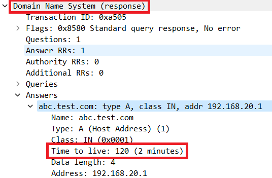
A: The timeout value of the IP cache is determined by the TTL (Time-To-Live) value of the DNS packet returned from the DNS server. In this example, it is 120 seconds. When the IP cache times out, it is automatically removed from the router. This is the detail of packet capture.
 Packet Detail of DNS Resolution
Q: Is it acceptable when the DNS server returns CNAME record rather than A record ?
A: Yes, it is not a problem. DNS resolution and HTTP communication is proceeded without any issues when CNAME record is returned by DNS Server. This is the detail of packet capture.
 DNS Packets in Inside
 Packet Detail of DNS Resolution
 HTTP Packets in Inside
Q: What is the command to transfer packet captures collected on a C8300 router to an FTP server ?
A: Use monitor capture <capture name> export bootflash:<capture name>.pcap and copy bootflash:<capture name>.pcap ftp://<user>:<password>@<FTP IP Address> commands to transfer packet captures to an FTP server. This is an example to transfer CAPIN to an FTP server.
monitor capture CAPIN export bootflash:CAPIN.pcap
copy bootflash:CAPIN.pcap ftp://<user>:<password>@<FTP IP Address>
Reference
Understand the Zone-Based Policy Firewall Design


 Feedback