Introduction
This document provides examples of basic Network Address Translation (NAT) and Port Address Translation (PAT) configurations on the Cisco Secure Adaptive Security Appliance (ASA) Firewall. This document also provides simplified network diagrams. Consult the ASA documentation for your ASA software version for more detailed information.
This document offers customized analysis of your Cisco device.
Refer to NAT configuration on ASA on ASA 5500/5500-X Series Security Appliances for more information.
Prerequisites
Requirements
Cisco recommends that you have knowledge of the Cisco Secure ASA Firewall.
Components Used
The information in this document is based on the Cisco Secure ASA Firewall Software Version 8.4.2 and later.
The information in this document was created from the devices in a specific lab environment. All of the devices used in this document started with a cleared (default) configuration. If your network is live, make sure that you understand the potential impact of any command.
Configure - Multiple NAT Statements with Manual and Auto NAT
Network Diagram
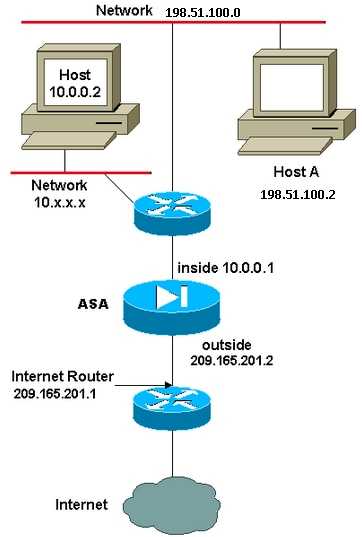
In this example, the ISP provides the network manager with an IP address block 209.165.201.0/27 that ranges from 209.165.201.1 to 209.165.201.30. The network manager decides to assign 209.165.201.1 to the inside interface on the Internet router, and 209.165.201.2 to the outside interface of the ASA.
The network administrator already has a Class C address assigned to the network, 198.51.100.0/24, and has some workstations that use these addresses in order to access the Internet. These workstations do not require any address translation because they already have valid addresses. However, new workstations are assigned addresses in the 10.0.0.0/8 network and they need to be translated (because 10.x.x.x is one of the unroutable address spaces per RFC 1918 .
In order to accommodate this network design, the network administrator must use two NAT statements and one global pool in the ASA configuration:
global (outside) 1 209.165.201.3-209.165.201.30 netmask 255.255.255.224
nat (inside) 1 10.0.0.0 255.0.0.0 0 0
This configuration does not translate the source address of any outbound traffic from the 198.51.100.0/24 network. It translates a source address in the 10.0.0.0/8 network into an address from the range 209.165.201.3 through 209.165.201.30.
Note: When you have an interface with a NAT policy and if there is no global pool to another interface, you need to use nat 0 in order to set up NAT exception.
ASA Version 8.3 and Later
Here is the configuration.
object network obj-10.0.0.0/8
 subnet 10.0.0.0 255.0.0.0

object network obj-198.51.100.0/24
 subnet 198.51.100.0 255.255.255.0

object network obj-natted
 range 209.165.201.3 209.165.201.30

object network any-1
 subnet 0.0.0.0 0.0.0.0

Using the Manual Nat statements:

nat (inside,outside) source static obj-198.51.100.0/24 obj-198.51.100.0/24
destination static any-1 any-1

nat (inside,outside) source dynamic obj-10.0.0.0/8 obj-natted

Using the Auto Nat statements:

object network obj-10.0.0.0/8
 subnet 10.0.0.0 255.0.0.0
 nat (inside,outside) dynamic obj-natted

object network obj-198.51.100.0/24
 subnet 198.51.100.0 255.255.255.0
 nat (inside,outside) static obj-198.51.100.0/24
Configure - Multiple Global Pools
Network Diagram
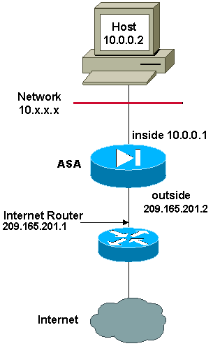
In this example, the network manager has two ranges of IP addresses that are registered on the Internet. The network manager must convert all of the internal addresses, which are in the 10.0.0.0/8 range, into registered addresses. The ranges of IP addresses that the network manager must use are 209.165.201.1 through 209.165.201.30 and 209.165.200.225 through 209.165.200.254. The network manager can do this with:
global (outside) 1 209.165.201.3-209.165.201.30 netmask 255.255.255.224
global (outside) 1 209.165.200.225-209.165.200.254 netmask 255.255.255.224
nat (inside) 1 0.0.0.0 0.0.0.0 0 0
Note: A wildcard addressing scheme is used in the NAT statement. This statement tells the ASA to translate any internal source address when it goes out to the Internet. The address in this command can be more specific if desired.
ASA Version 8.3 and Later
Here is the configuration.
object network obj-natted
range 209.165.201.3 209.165.201.30

object network obj-natted-2
range 209.165.200.225 209.165.200.254

object network any-1
subnet 0.0.0.0 0.0.0.0

Using the Manual Nat statements:

nat (inside,outside) source dynamic any-1 obj-natted
nat (inside,outside) source dynamic any-1 obj-natted-2

Using the Auto Nat statements:

object network any-1
subnet 0.0.0.0 0.0.0.0
nat (inside,outside) dynamic obj-natted

object network any-2
 subnet 0.0.0.0 0.0.0.0
 nat (inside,outside) dynamic obj-natted-2
Configure - Mix NAT and PAT Statements
Network Diagram
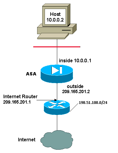
In this example, the ISP provides the network manager with a range of addresses from 209.165.201.1 to 209.165.201.30 for the company to use. The network manager has decided to use 209.165.201.1 for the inside interface on the Internet router and 209.165.201.2 for the outside interface on the ASA. You are then left with 209.165.201.3 through 209.165.201.30 to use for the NAT pool. However, the network manager knows that, at any one time, there can be more than 28 people who try to go out of the ASA. The network manager has decided to take 209.165.201.30 and make it a PAT address so that multiple users can share one address at the same time.
These commands instruct the ASA to translate the source address to 209.165.201.3 through 209.165.201.29 for the first 27 internal users to pass across the ASA. After these addresses are exhausted, then the ASA translates all subsequent source addresses to 209.165.201.30 until one of the addresses in the NAT pool becomes free.
Note: A wildcard addressing scheme is used in the NAT statement. This statement tells the ASA to translate any internal source address when it goes out to the Internet. The address in this command can be more specific if desired.
ASA Version 8.3 and Later
Here is the configuration.
Using the Manual Nat statements:
object network any-1
 subnet 0.0.0.0 0.0.0.0

object network obj-natted
 range 209.165.201.3 209.165.201.30

object network obj-natted-2
 subnet 209.165.201.30 255.255.255.224

nat (inside,outside) source dynamic 0.0.0.0/0 obj-natted
nat (inside,outside) source dynamic 0.0.0.0/0 obj-natted-2

Using the Auto Nat statements:

object network any-1
 subnet 0.0.0.0 0.0.0.0
 nat (inside,outside) dynamic obj-natted

object network any-2
 subnet 0.0.0.0 0.0.0.0
 nat (inside,outside) dynamic obj-natted-2
Configure - Multiple NAT Statements with Manual Statements
Network Diagram
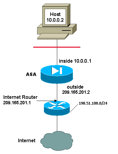
In this example, the ISP again provides the network manager with a range of addresses from 209.165.201.1 to 209.165.201.30. The network manager decides to assign 209.165.201.1 to the inside interface on the Internet router and 209.165.201.2 to the outside interface of the ASA.
However, in this scenario, another private LAN segment is placed off of the Internet router. The network manager prefers not to waste addresses from the global pool when hosts in these two networks talk to each other. The network manager still needs to translate the source address for all of the internal users (10.0.0.0/8) when it goes out to the Internet.
This configuration does not translate those addresses with a source address of 10.0.0.0/8 and a destination address of 198.51.100.0/24. It translates the source address from any traffic initiated from within the 10.0.0.0/8 network and destined for anywhere other than 198.51.100.0/24 into an address from the range 209.165.201.3 through 209.165.201.30.
If you have the output of a write terminal command from your Cisco device, you can use the Output Interpreter Tool (registered customers only).
ASA Version 8.3 and Later
Here is the configuration.
Using the Manual Nat statements:

object network obj-10.0.0.0/8
 subnet 10.0.0.0 255.0.0.0

object network obj-198.51.100.0/24
 subnet 198.51.100.0 255.255.255.0

object network obj-natted
 range 209.165.201.3 209.165.201.30

nat (inside,outside) source static obj-10.0.0.0/8 obj-10.0.0.0/8 destination
 static obj-198.51.100.0/24 obj-198.51.100.0/24

nat (inside,outside) source dynamic obj-10.0.0.0/8 obj-natted

Using the Auto Nat statements:

object network obj-natted
 range 209.165.201.3 209.165.201.30
 nat (inside,outside) source static obj-10.0.0.0/8 obj-10.0.0.0/8 destination
 static obj-198.51.100.0/24 obj-198.51.100.0/24

object network obj-10.0.0.0/8
 subnet 10.0.0.0 255.0.0.0
 nat (inside,outside) dynamic obj-natted
Configure - Use Policy NAT
Network Diagram
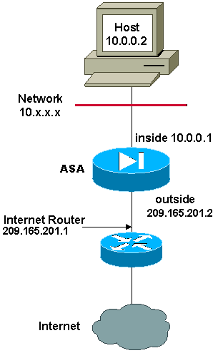
When you use an access list with the nat command for any NAT ID other than 0, you enable policy NAT.
Policy NAT allows you to identify local traffic for address translation by the specification of the source and destination addresses (or ports) in an access list. Regular NAT uses source addresses/ports only. Policy NAT uses both source and destination addresses/ports.
Note: All types of NAT support policy NAT except for NAT exemption (nat 0 access-list). NAT exemption uses an Access Control List (ACL) in order to identify the local addresses, but differs from policy NAT because the ports are not considered.
With policy NAT, you can create multiple NAT or static statements that identify the same local address as long as the source/port and destination/port combination is unique for each statement. You can then match different global addresses to each source/port and destination/port pair.
In this example, the network manager has to provide access for destination IP address 172.30.1.11 for port 80 (web) and port 23 (Telnet), but must use two different IP addresses as a source address. 209.165.201.3 is used as a source address for the Web and 209.165.201.4 is used for Telnet, and must convert all of the internal addresses, which are in the 10.0.0.0/8 range. The network manager can do this with:
access-list WEB permit tcp 10.0.0.0 255.0.0.0
172.30.1.11  255.255.255.255 eq 80
access-list TELNET permit tcp 10.0.0.0 255.0.0.0 172.30.1.11
255.255.255.255 eq 23

nat (inside) 1 access-list WEB
nat (inside) 2 access-list TELNET
global (outside) 1 209.165.201.3  255.255.255.224
global (outside) 2 209.165.201.4  255.255.255.224
ASA Version 8.3 and Later
Here is the configuration.
Using the Manual Nat statements:

object network obj-10.0.0.0/8
 subnet 10.0.0.0 255.0.0.0

object network obj-172.30.1.11
 host 172.30.1.11

object network obj-209.165.201.3
   host 209.165.201.3

object network obj-209.165.201.4
 host 209.165.201.4

object service obj-23
 service tcp destination eq telnet

object service obj-80
 service tcp destination eq telnet

nat (inside,outside) source dynamic obj-10.0.0.0/8 obj-209.165.201.3 destination
 static obj-172.30.1.11   obj-172.30.1.11   service obj-80 obj-80
nat (inside,outside) source dynamic obj-10.0.0.0/8 obj-209.165.201.4 destination
 static obj-172.30.1.11   obj-172.30.1.11   service obj-23 obj-23
Note: For more information about the configuration of NAT and PAT on ASA Version 8.4, refer to Information About NAT.
For more information about the configuration of access lists on ASA Version 8.4, refer to Information About Access Lists.
Verify
Try to access a website via HTTP with a web browser. This example uses a site that is hosted at 198.51.100.100. If the connection is successful, the output in the next section can be seen on the ASA CLI.
Connection
ASA(config)# show connection address 10.0.0.2
16 in use, 19 most used
TCP outside  198.51.100.100:80 inside  10.0.0.2:57431, idle 0:00:06, bytes 9137,
flags UIO
The ASA is a stateful firewall, and return traffic from the web server is allowed back through the firewall because it matches a connection in the firewall connection table. Traffic that matches a connection that preexists is allowed through the firewall without being blocked by an interface ACL.
In the previous output, the client on the inside interface has established a connection to the 198.51.100.100 host off of the outside interface. This connection is made with the TCP protocol and has been idle for six seconds. The connection flags indicate the current state of this connection. More information about connection flags can be found in ASA TCP Connection Flags.
Syslog
ASA(config)# show log | in 10.0.0.2

Jun 28 2014 11:31:23: %ASA-6-305011: Built dynamic TCP translation from inside:
10.0.0.2/57431 to outside:209.165.201.3/57431

Jun 28 2014 11:31:23: %ASA-6-302013: Built outbound TCP connection 2921 for outside:
198.51.100.100/80 (198.51.100.100/80) to inside:10.0.0.2/57431 (209.165.201.3/57431)
The ASA Firewall generates syslogs during normal operation. The syslogs range in verbosity based on the logging configuration. The output shows two syslogs that are seen at level six, or 'informational' level.
In this example, there are two syslogs generated. The first is a log message that indicates that the firewall has built a translation, specifically a dynamic TCP translation (PAT). It indicates the source IP address and port and the translated IP address and port as the traffic traverses from the inside to the outside interfaces.
The second syslog indicates that the firewall has built a connection in its connection table for this specific traffic between the client and server. If the firewall was configured in order to block this connection attempt, or some other factor inhibited the creation of this connection (resource constraints or a possible misconfiguration), the firewall would not generate a log that indicates that the connection was built. Instead it would log a reason for the connection to be denied or an indication about what factor inhibited the connection from being created.
NAT Translations (Xlate)
ASA(config)# show xlate local 10.0.0.2
3 1in use, 810 most used
Flags: D - DNS, e - extended, I - identity, i - dynamic, r - portmap,
       s - static, T - twice, N - net-to-net
TCP PAT from inside:10.0.0.2/58799 to outside:209.165.201.3/57431 flags ri idle
0:12:22 timeout 0:00:30
As part of this configuration, PAT is configured in order to translate the internal host IP addresses to addresses that are routable on the Internet. In order to confirm that these translations are created, you can check the xlate (translation) table. The command show xlate, when combined with the local keyword and the internal host's IP address, shows all of the entries present in the translation table for that host. The previous output shows that there is a translation currently built for this host between the inside and outside interfaces. The inside host IP and port are translated to the 10.165.200.226 address per the configuration.
The flags listed, r i , indicate that the translation is dynamic and a portmap. More information about different NAT configurations can be found in Information About NAT.
Troubleshoot
There is currently no specific troubleshooting information available for this configuration.


 Feedback