Configure FTD Multi-Instance High-availability on Firepower 4100
Available Languages
Download Options
Bias-Free Language
The documentation set for this product strives to use bias-free language. For the purposes of this documentation set, bias-free is defined as language that does not imply discrimination based on age, disability, gender, racial identity, ethnic identity, sexual orientation, socioeconomic status, and intersectionality. Exceptions may be present in the documentation due to language that is hardcoded in the user interfaces of the product software, language used based on RFP documentation, or language that is used by a referenced third-party product. Learn more about how Cisco is using Inclusive Language.
Contents
Introduction
This document describes how to configure Failover in FTD Container Instances (Multi-Instance).
Prerequisites
Requirements
Cisco recommends that you have knowledge of Firepower Management Center and Firewall Threat Defense.
Components Used
Cisco Firepower Management Center Virtual 7.2.5
Cisco Firepower 4145 NGFW Appliance (FTD) 7.2.5
Firepower eXtensible Operating System (FXOS) 2.12 (0.498)
Windows 10
The information in this document was created from the devices in a specific lab environment. All of the devices used in this document started with a cleared (default) configuration. If your network is live, ensure that you understand the potential impact of any command.
Before deploying FTD Multi-Instance, it is important to understand how it can impact your system performance and to plan accordingly. Always refer to Cisco official documentation or consult with a Cisco technical representative to ensure optimal deployment and configuration.
Background Information
Multi-Instance is a feature of Firepower Threat Defense (FTD) which is similar to ASA multiple context mode. It allows you to run multiple, separate container Instances of FTD on a single piece of hardware. Each container Instance allows hard resource separation, separate configuration management, separate reloads, separate software updates, and full threat defense feature support. This is particularly useful for organizations that require different security policies for different departments or projects, but do not want to invest in multiple separate hardware appliances. The Multi-Instance feature is currently supported on the Firepower 3100, 4100, 4200 and 9300 series security appliance running FTD 6.4 and later.
This document uses Firepower4145 which supports maximum 14 Container Instances. For the maximum Instances supported in Firepower Appliance, please refer to Maximum Container Instances and Resources per Model.
Network Diagram
This document introduces the configuration and verification for HA in Multi-Instance on this diagram.
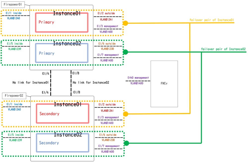 Logical Configuration Diagram
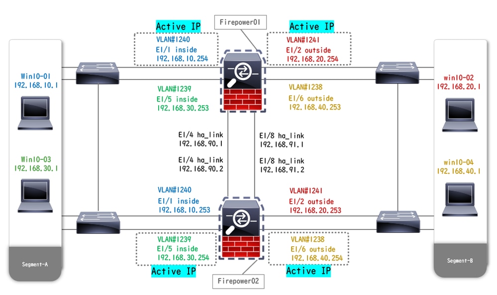 Physical Configuration Diagram
Configurations
Step 1. Pre-configure Interfaces
a. Navigate to Interfaces on FCM. Set 2 mgmt interfaces. In this example Ethernet1/3 and Ethernet1/7.
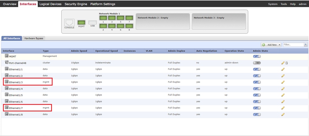 Pre-configure Interfaces
Step 2. Add 2 Resource Profiles for Container Instances.
a. Navigate to Platform Settings > Resource Profiles > Add on FCM. Set 1st resource profile.
In this example :
・Name : Instance01
・Number of Cores : 10

Note: For HA of container Instance pair, they must use the same resource profile attributes.
Set the name of the profile between 1 and 64 characters. Note that you cannot change the name of this profile after you add it.
Set the number of cores for the profile, between 6 and the maximum.
 Add 1st Resource Profile
b. Repeat a. in Step 2, to configure 2nd resource profile.
In this example :
・Name : Instance02
・Number of Cores : 20
 Add 2nd Resource Profile
c. Check 2 resource profiles are added successfully.
 Confirm Resource Profile
Step 3. (Optional)Add a MAC Pool Prefix of virtual MAC address for Container Instance Interfaces.
You can set virtual MAC address for Active/Stanby interface manually. If Virtual MAC Addresses are not set , for multi-Instance capability, the chassis automatically generates MAC addresses for Instance interfaces, and guarantees that a shared interface in each Instance uses a unique MAC address.
Please check Add a MAC Pool Prefix and View MAC Addresses for Container Instance Interfaces for more detail about MAC address.
Step 4. Add a Standalone Instance.
a. Navigate to Logical Devices > Add Standalone. Set 1st Instance.
In this example :
・Device Name : FTD01
・Instance Type : Container

Note: The only way to deploy a container application is to pre-deploy an App-Instance with Instance Type set to Container. Ensure to select Container.
You cannot change this name after you add the logical device.
 Add Instance
Step 5. Configure Interfaces
a. Set Resource Profile, Management Interface, Management IP for Instance01.
In this example :
・Resource Profile : Instance01
・Management Interface : Ethernet1/3
・ManagementIP : x.x.1.1
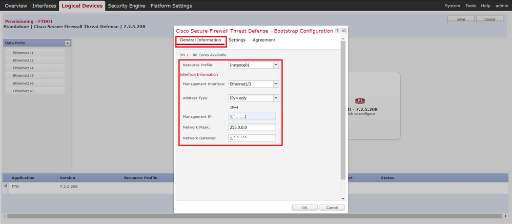 Configure Profile/Management Interface/Management IP
b. Set Data Interfaces.
In this example :
・Ethernet1/1 (used for inside)
・Ethernet1/2 (used for outside)
・Ethernet1/4 (used for HA link)
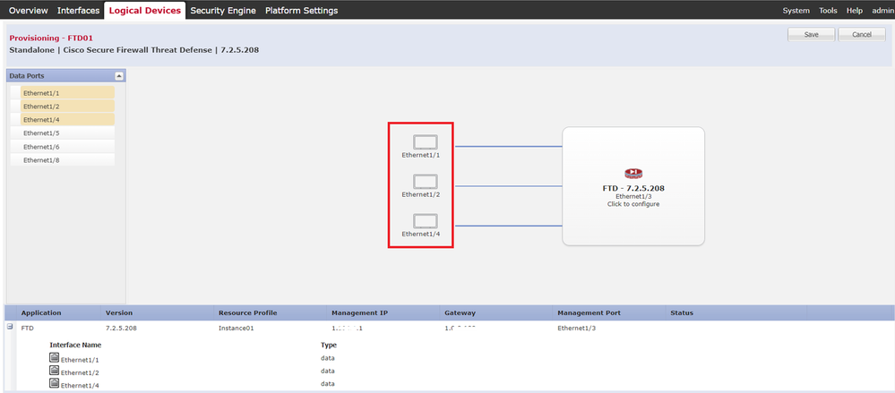 Set Data Interfaces
c. Navigate to Logical Devices. Waiting for Instance bootup.
 Confirm Status of Instance01
d. Repeat a. in Step 4.a and Step 5.a through c to add 2nd Instance and set detail for it.
In this example :
・Device Name : FTD11
・Instance Type : Container
・Resource Profile : Instance02
・Management Interface : Ethernet1/7
・ManagementIP : x.x.10.1
・Ethernet1/5 = inside
・Ethernet1/6 = outside
・Ethernet1/8 = HA link
e. Confirm 2 Instances are Online status on FCM.
 Confirm Instance Status In Primary Device
f. (Optional)Run scope ssa , scope slot 1 and show app-Instance command to confrim 2 Instances are Online status on Firepower CLI.
FPR4145-ASA-K9# scope ssa
FPR4145-ASA-K9 /ssa # scope slot 1
FPR4145-ASA-K9 /ssa/slot # show app-Instance

Application Instance:
App Name Identifier Admin State Oper State Running Version Startup Version Deploy Type Turbo Mode Profile Name Cluster State Cluster Role
---------- ---------- ----------- ---------------- --------------- --------------- ----------- ---------- ------------ --------------- ------------
ftd FTD01 Enabled Online 7.2.5 208 7.2.5 208 Container No Instance01 Not Applicable None     --> FTD01 Instance is Online
ftd FTD11 Enabled Online 7.2.5 208 7.2.5 208 Container No Instance02 Not Applicable None     --> FTD11 Instance is Online
g. Do the same on the Secondary device. Confirm 2 Instances are Online status.
 Confirm Instance Status In Secondary Device
Step 6. Add High Availability Pair For Each Instance.
a. Navigate to Devices > Add Device on FMC. Add all Instances to FMC.
In this example :
・Dispaly Name for Instance01 of FTD1 : FTD1_FTD01
・Dispaly Name for Instance02 of FTD1 : FTD1_FTD11
・Dispaly Name for Instance01 of FTD2 : FTD2_FTD02
・Dispaly Name for Instance02 of FTD2 : FTD2_FTD12
This image shows the setting for FTD1_FTD01.
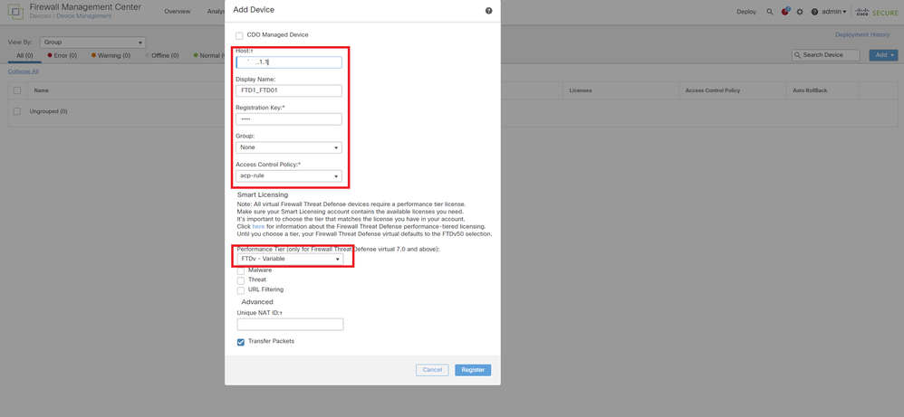 Add FTD Instance To FMC
b. Confirm all Instances are Normal.
 Confirm Instance Status In FMC
c. Navigate to Devices > Add High Availability. Set 1st failover pair.
In this example :
・Name : FTD01_FTD02_HA
・Primary Peer : FTD1_FTD01
・Secondary Peer : FTD2_FTD02

Note: Ensure to select the correct unit as the primary unit.
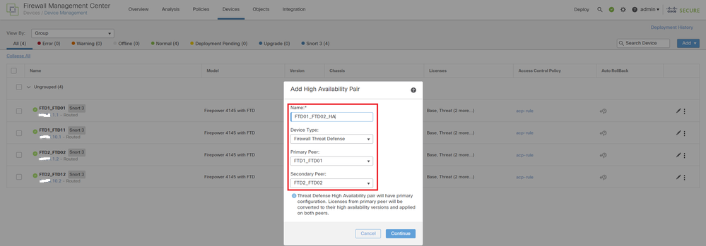 Add 1st Failover Pair
d. Set IP for failover link in 1st failover pair.
In this example :
・High Availability Link : Ethernet1/4
・State Link : Ethernet1/4
・Primary IP : 192.168.90.1/24
・Secondary IP : 192.168.90.2/24
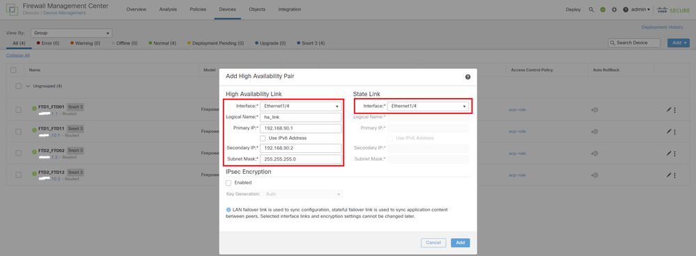 Set HA Interface and IP for 1st Failover Pair
e. Confirm the status of failover
・FTD1_FTD01 : Primay, Active
・FTD2_FTD02 : Secondary, Standby
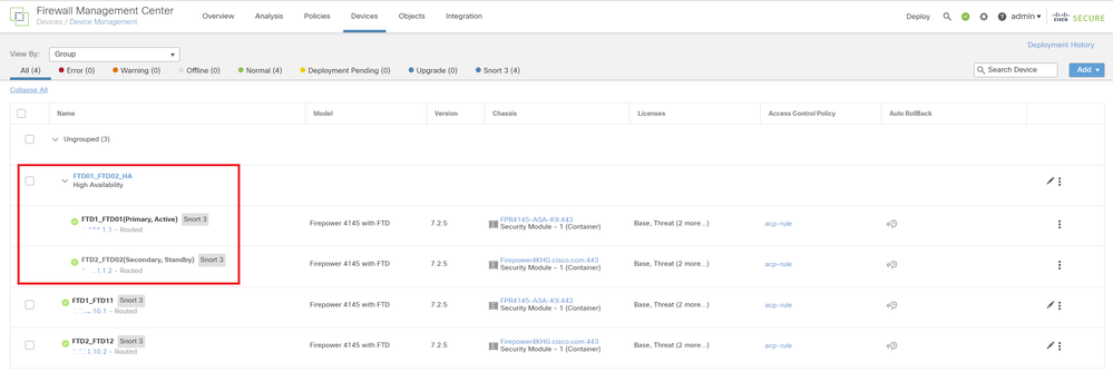 Confirm Status Of 1st Failover Pair
f. Navigate to Devices > Click FTD01_FTD02_HA (in this example) > Interfaces. Set Active IP for Data Interface.
In this example :
・Ethernet1/1 (inside) : 192.168.10.254/24
・Ethernet1/2 (outside) : 192.168.20.254/24
・Ethernet1/3 (diagnostic) : 192.168.80.1/24
This image shows the setting for Active IP of Ethernet1/1.
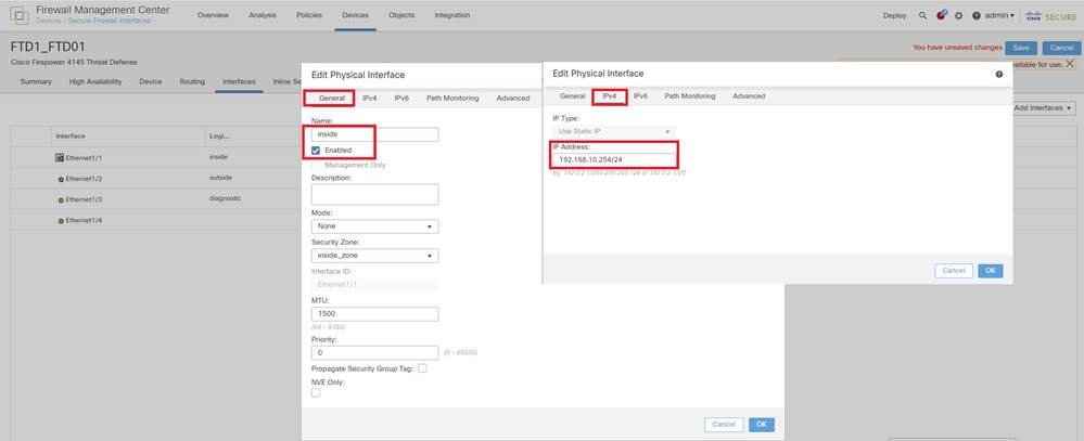 Set Active IP for Data Interface
g. Navigate to Devices > Click FTD01_FTD02_HA (in this example) > High Availability. Set Standby IP for Data Interface.
In this example :
・Ethernet1/1 (inside) : 192.168.10.253/24
・Ethernet1/2 (outside) : 192.168.20.253/24
・Ethernet1/3 (diagnostic) : 192.168.80.2/24
This image shows the setting for Standby IP of Ethernet1/1.
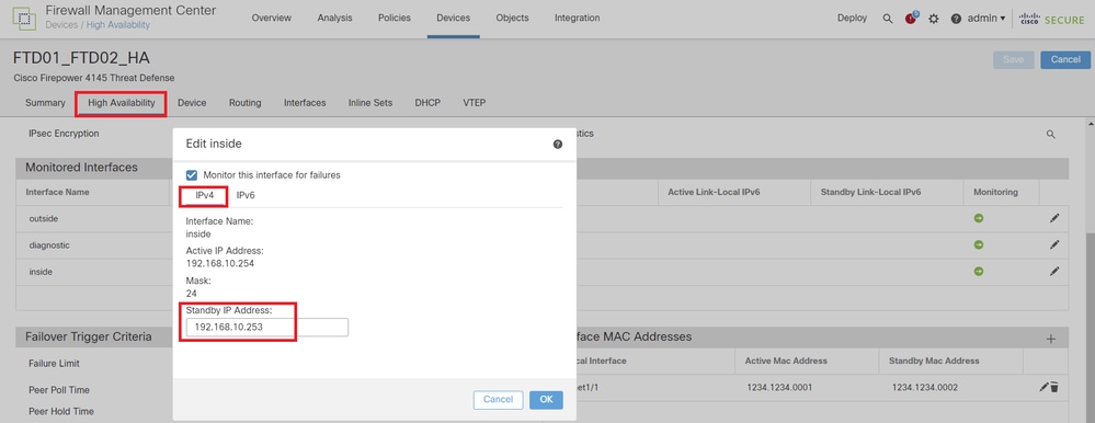 Set Standby IP for Data Interface
h. Repeat Step 6.c through g, to add 2nd failover pair.
In this example :
・Name : FTD11_FTD12_HA
・Primary Peer : FTD1_FTD11
・Secondary Peer : FTD2_FTD12
・High Availability Link : Ethernet1/8
・State Link : Ethernet1/8
・Ethernet1/8 (ha_link Active) : 192.168.91.1/24
・Ethernet1/5 (inside Active) : 192.168.30.254/24
・Ethernet1/6 (outside Active) : 192.168.40.254/24
・Ethernet1/7 (diagnostic Active) : 192.168.81.1/24
・Ethernet1/8 (ha_link Standby) : 192.168.91.2/24
・Ethernet1/5 (inside Standby) : 192.168.30.253/24
・Ethernet1/6 (outside Standby) : 192.168.40.253/24
・Ethernet1/7 (diagnostic Standby) : 192.168.81.2/24
i. Navigate to Logical Devices > Add Standalone. Set ACP rule to permit the traffic from inside to outisde.
 Set ACP Rule
j. Deploy the setting to FTD.
k. Confirm HA status in CLI
The HA status for each Instance is also confirmed in Firepower CLI which is same as ASA.
Run show running-config failover and show failover command to confrim HA status of FTD1_FTD01 (Primary Instance01) .
// confrim HA status of FTD1_FTD01 (Instance01 of Primary Device)
> show running-config failover
failover
failover lan unit primary
failover lan interface ha_link Ethernet1/4
failover replication http
failover link ha_link Ethernet1/4
failover interface ip ha_link 192.168.90.1 255.255.255.0 standby 192.168.90.2

> show failover
Failover On
Failover unit Primary
Failover LAN Interface: ha_link Ethernet1/4 (up)
......
This host: Primary - Active  <---- Instance01 of FPR01 is Active
Interface diagnostic (192.168.80.1): Normal (Monitored)
Interface inside (192.168.10.254): Normal (Monitored)
Interface outside (192.168.20.254): Normal (Monitored)
......
Other host: Secondary - Standby Ready  <---- Instance01 of FPR02 is Standby
Interface diagnostic (192.168.80.2): Normal (Monitored)
Interface inside (192.168.10.253): Normal (Monitored)
Interface outside (192.168.20.253): Normal (Monitored)
Run show running-config failover and show failover command to confrim HA status of FTD1_FTD11 (Primay Instance02) .
// confrim HA status of FTD1_FTD11 (Instance02 of Primary Device)
> show running-config failover
failover
failover lan unit primary
failover lan interface ha_link Ethernet1/8
failover replication http
failover link ha_link Ethernet1/8
failover interface ip ha_link 192.168.91.1 255.255.255.0 standby 192.168.91.2

> show failover
Failover On
Failover unit Primary
Failover LAN Interface: ha_link Ethernet1/8 (up)
......
This host: Primary - Active  <---- Instance02 of FPR01 is Active
Interface diagnostic (192.168.81.1): Normal (Monitored)
Interface inside (192.168.30.254): Normal (Monitored)
Interface outside (192.168.40.254): Normal (Monitored)
......
Other host: Secondary - Standby Ready  <---- Instance02 of FPR02 is Standby
Interface diagnostic (192.168.81.2): Normal (Monitored)
Interface inside (192.168.30.253): Normal (Monitored)
Interface outside (192.168.40.253): Normal (Monitored)
Run show running-config failover and show failover command to confrim HA status of FTD2_FTD02 (Secondary Instance01) .
// confrim HA status of FTD2_FTD02 (Instance01 of Secondary Device)
> show running-config failover
failover
failover lan unit secondary
failover lan interface ha_link Ethernet1/4
failover replication http
failover link ha_link Ethernet1/4
failover interface ip ha_link 192.168.90.1 255.255.255.0 standby 192.168.90.2

> show failover
Failover On
Failover unit Secondary
Failover LAN Interface: ha_link Ethernet1/4 (up)
......
This host: Secondary - Standby Ready  <---- Instance01 of FPR02 is Standby
Interface diagnostic (192.168.80.2): Normal (Monitored)
Interface inside (192.168.10.253): Normal (Monitored)
Interface outside (192.168.20.253): Normal (Monitored)
......
Other host: Primary - Active <---- Instance01 of FPR01 is Active
Active time: 31651 (sec)
slot 0: UCSB-B200-M3-U hw/sw rev (0.0/9.18(3)53) status (Up Sys)
Interface diagnostic (192.168.80.1): Normal (Monitored)
Interface inside (192.168.10.254): Normal (Monitored)
Interface outside (192.168.20.254): Normal (Monitored)
Run show running-config failover and show failover command to confrim HA status of FTD2_FTD12 (Seconday Instance02) .
// confrim HA status of FTD2_FTD12 (Instance02 of Secondary Device)
> show running-config failover
failover
failover lan unit secondary
failover lan interface ha_link Ethernet1/8
failover replication http
failover link ha_link Ethernet1/8
failover interface ip ha_link 192.168.91.1 255.255.255.0 standby 192.168.91.2

> show failover
Failover On
Failover unit Secondary
Failover LAN Interface: ha_link Ethernet1/8 (up)
......
This host: Secondary - Standby Ready <---- Instance02 of FPR02 is Standby
Interface diagnostic (192.168.81.2): Normal (Monitored)
Interface inside (192.168.30.253): Normal (Monitored)
Interface outside (192.168.40.253): Normal (Monitored)
......
Other host: Primary - Active <---- Instance02 of FPR01 is Active
Active time: 31275 (sec)
slot 0: UCSB-B200-M3-U hw/sw rev (0.0/9.18(3)53) status (Up Sys)
Interface diagnostic (192.168.81.1): Normal (Monitored)
Interface inside (192.168.30.254): Normal (Monitored)
Interface outside (192.168.40.254): Normal (Monitored)
l. Confirm license consumption
All licenses are consumed per security engine/chassis, and not per container Instance.
・Baselicenses are automatically assigned: one per security engine/chassis.
・Feature licenses are manually assigned to each Instance, but you only consume one license per feature persecurity engine/chassis. For a specific feature license, you only need a total of 1 license, regardless of the number of Instances in use.
This table show how the licenses are consumed in this document.
|
FPR01 |
Instance01 |
Base, URL Filtering, Malware, Threat |
|
Instance02 |
Base, URL Filtering, Malware, Threat |
|
|
FPR02 |
Instance01 |
Base, URL Filtering, Malware, Threat |
|
Instance02 |
Base, URL Filtering, Malware, Threat |
Total Number of Licenses
|
Base |
URL Filtering |
Malware |
Threat |
|
2 |
2 |
2 |
2 |
Confirm the number of consumed licenses in FMC GUI.
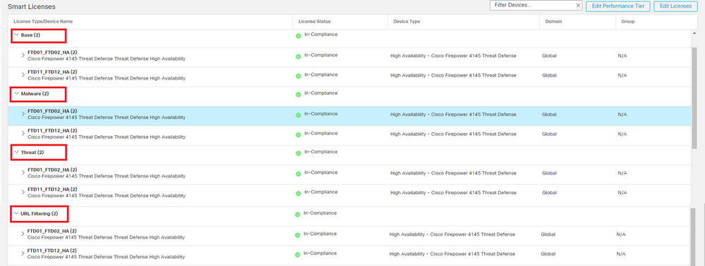 Confirm Consumed Licenses
Verify
When crash occured on FTD1_FTD01 (Primary Instance01), the failover of Instance01 is triggered and data interfaces on the Standby side takes over the IP/MAC address of the original Active Interface, ensuring the traffic (FTP connection in this document) to be continuously passed by Firepower.
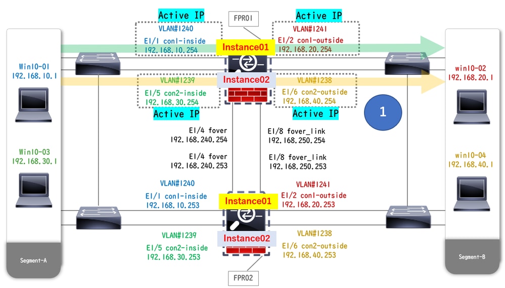 Before Crash
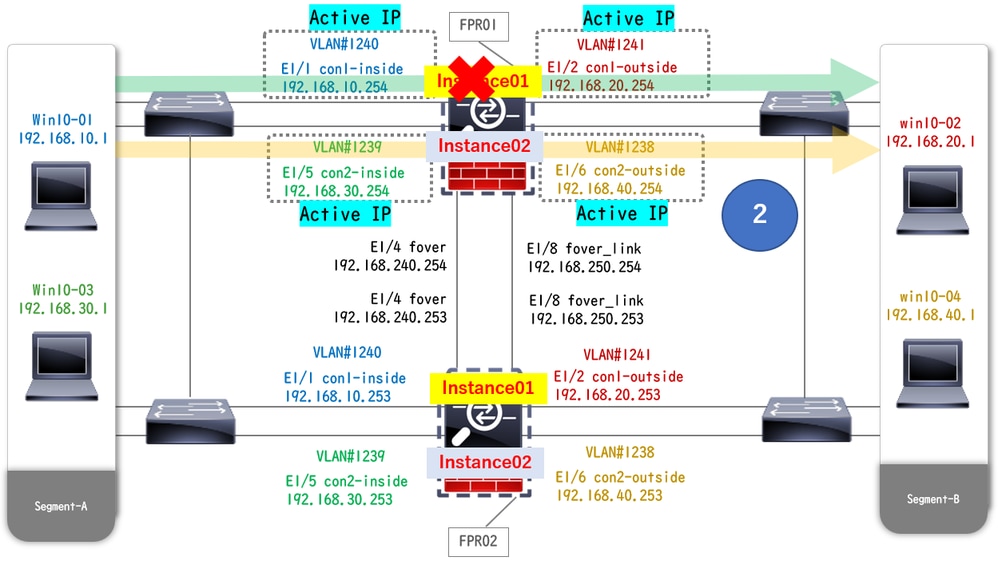 During Crash
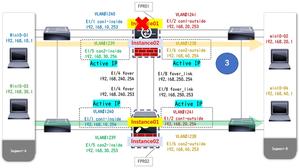 Failover Is Triggered
Step 1. Initiate FTP connection from Win10-01 to Win10-02.
Step 2. Run show conn
// Confirm the connection in Instance01 of FPR01
> show conn
TCP outside 192.168.20.1:21 inside 192.168.10.1:49723, idle 0:00:11, bytes 529, flags UIO N1

// Confirm the connection in Instance01 of FPR02
> show conn
TCP outside 192.168.20.1:21 inside 192.168.10.1:49723, idle 0:00:42, bytes 530, flags UIO N1
Step 3. Initiate FTP connection from Win10-03 to Win10-04.
Step 4. Run show conn command to confrim FTP connection is established in both of Instance02.
// Confirm the connection in Instance02 of FPR01
> show conn
TCP outside 192.168.40.1:21 inside 192.168.30.1:52144, idle 0:00:02, bytes 530, flags UIO N1

// Confirm the connection in Instance02 of FPR02
> show conn
TCP outside 192.168.40.1:21 inside 192.168.30.1:52144, idle 0:00:13, bytes 530, flags UIO N1
Step 5. Run connect ftd FTD01 and system support diagnostic-cli command to enter into ASA CLI. Run enable and crashinfo force watchdog command to force crash Instance01 in Primary/Active unit.
Firepower-module1>connect ftd FTD01
> system support diagnostic-cli
FTD01> enable
Password:
FTD01#

FTD01# crashinfo force watchdog
reboot. Do you wish to proceed? [confirm]:
Step 6. Failover occurs in Instance01 and the FTP connection is not interrupted. Run show failover and show conn command to confirm the stauts of Instance01 in FPR02.
> show failover
Failover On
Failover unit Secondary
Failover LAN Interface: ha_link Ethernet1/4 (up)
......
This host: Secondary - Active <---- Instance01 of FPR02 is Switching to Active
Interface diagnostic (192.168.80.1): Normal (Waiting)
Interface inside (192.168.10.254): Unknown (Waiting)
Interface outside (192.168.20.254): Unknown (Waiting)
......
Other host: Primary - Failed
Interface diagnostic (192.168.80.2): Unknown (Monitored)
Interface inside (192.168.10.253): Unknown (Monitored)
Interface outside (192.168.20.253): Unknown (Monitored)

> show conn
TCP outside 192.168.20.1:21 inside 192.168.10.1:49723, idle 0:02:25, bytes 533, flags U N1
Step 7. The crash occurred in Instance01 had no effect to Instance02. Run show failover and show conn command to confirm the stauts of Instance02.
> show failover
Failover On
Failover unit Secondary
Failover LAN Interface: ha_link Ethernet1/8 (up)
......
This host: Secondary - Standby Ready
Interface diagnostic (192.168.81.2): Normal (Monitored)
Interface inside (192.168.30.253): Normal (Monitored)
Interface outside (192.168.40.253): Normal (Monitored)
......
Other host: Primary - Active
Interface diagnostic (192.168.81.1): Normal (Monitored)
Interface inside (192.168.30.254): Normal (Monitored)
Interface outside (192.168.40.254): Normal (Monitored)

> show conn
TCP outside 192.168.40.1:21 inside 192.168.30.1:52144, idle 0:01:18, bytes 533, flags UIO N1
Step 8. Navigate to Devices > All on FMC. Confirm the HA status.
・FTD1_FTD01 : Primay, Standby
・FTD2_FTD02 : Secondary, Active
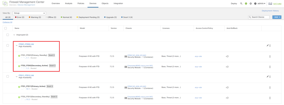 Confirm HA Status
Step 9. (Optional)After the Instance01 of FPR01 returns to normal, you can manually switch the status of HA. This can be done by either FMC GUI or FRP CLI.
On FMC, navigate to Devices > All. Click Switch Active Peer to switch HA status for FTD01_FTD02_HA.
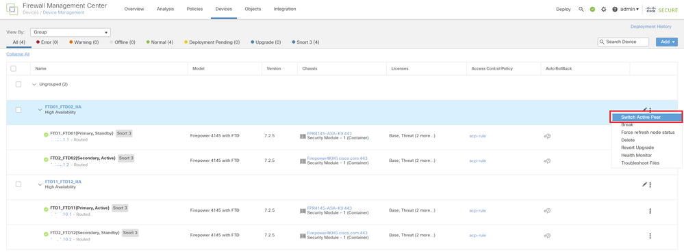 Switch HA Status
On Firepower CLI, Run connect ftd FTD01 and system support diagnostic-cli command to enter into ASA CLI. Run enable and failover active command to switch HA for FTD01_FTD02_HA.
Firepower-module1>connect ftd FTD01
> system support diagnostic-cli
Attaching to Diagnostic CLI ... Press 'Ctrl+a then d' to detach.
Type help or '?' for a list of available commands.

firepower> enable
firepower# failover active
Troubleshoot
In order to validate the the status of failover, run show failover and show failover history command.
> show failover
Failover On
Failover unit Secondary
Failover LAN Interface: ha_link Ethernet1/8 (up)
......
This host: Secondary - Standby Ready
Interface diagnostic (192.168.81.2): Normal (Monitored)
Interface inside (192.168.30.253): Normal (Monitored)
Interface outside (192.168.40.253): Normal (Monitored)
......
Other host: Primary - Active
Interface diagnostic (192.168.81.1): Normal (Monitored)
Interface inside (192.168.30.254): Normal (Monitored)
Interface outside (192.168.40.254): Normal (Monitored)

> show failover history
==========================================================================
From State                 To State                   Reason
==========================================================================
07:26:52 UTC Jan 22 2024
Negotiation                Cold Standby               Detected an Active peer

07:26:53 UTC Jan 22 2024
Cold Standby               App Sync                   Detected an Active peer

07:28:14 UTC Jan 22 2024
App Sync                   Sync Config                Detected an Active peer

07:28:18 UTC Jan 22 2024
Sync Config                Sync File System           Detected an Active peer

07:28:18 UTC Jan 22 2024
Sync File System           Bulk Sync                  Detected an Active peer

07:28:33 UTC Jan 22 2024
Bulk Sync                  Standby Ready              Detected an Active peer
Run debug fover <option>
> debug fover
  auth       Failover Cloud authentication
  cable      Failover LAN status
  cmd-exec   Failover EXEC command execution
  conn       Failover Cloud connection
  fail       Failover internal exception
  fmsg       Failover message
  ifc        Network interface status trace
  open       Failover device open
  rx         Failover Message receive
  rxdmp      Failover recv message dump (serial console only)
  rxip       IP network failover packet recv
  snort      Failover NGFW mode snort processing
  switch     Failover Switching status
  sync       Failover config/command replication
  synccount  Failover Sync Count
  tx         Failover Message xmit
  txdmp      Failover xmit message dump (serial console only)
  txip       IP network failover packet xmit
  verbose    Enable verbose logging
  verify     Failover message verify
Reference
https://www.cisco.com/c/en/us/support/docs/security/firepower-management-center/212699-configure-ftd-high-availability-on-firep.html
https://www.cisco.com/c/en/us/td/docs/security/firepower/fxos/multi-Instance/multi-Instance_solution.html
Revision History
| Revision | Publish Date | Comments |
|---|---|---|
1.0 |
06-Feb-2024 |
Initial Release |
Contributed by Cisco Engineers
- Jian ZhangTechnical Consulting Engineer
Contact Cisco
- Open a Support Case

- (Requires a Cisco Service Contract)
 Feedback