Introduction
This document describes how to configure the VXLAN Interfaces on Secure Firewall Threat Defense (FTD) with the Secure Firewall Management Center (FMC)
Prerequisites
Requirements
Cisco recommends that you know these topics:
- Basic VLAN/VXLAN concepts.
- Basic Network knowledge.
- Basic Cisco Secure Management Center experience.
- Basic Cisco Secure Firewall Threat Defense experience.
Components Used
The information in this document is based on these software and hardware versions:
- Cisco Secure Firewall Management Center Virtual (FMCv) VMware running 7.2.4 release.
- Cisco Secure Firewall Threat Defense Virtual Appliance (FTDv) VMware running 7.2.4 release.
The information in this document was created from the devices in a specific lab environment. All of the devices used in this document started with a cleared (default) configuration. If your network is live, ensure that you understand the potential impact of any command.
Background information
Virtual Extensible VLAN (VXLAN) provides Ethernet Layer 2 network services as traditional VLAN does. Due to the high demand for VLAN segments in virtual environments, VXLAN provides greater extensibility, flexibility, and also defines a MAC-in-UDP encapsulation scheme where the original Layer 2 frame has a VXLAN header added and is then placed in a UDP-IP packet. With this MAC-in-UDP encapsulation, VXLAN tunnels the Layer 2 network over the Layer 3 network. VXLAN offers the next benefits:
- VLAN Flexibility in multitenant segments:
- Higher scalability to address more Layer 2 (L2) segments.
- Improved network utilization.
The Cisco Secure Firewall Threat Defense (FTD) supports two types of VXLAN encapsulation.
- VXLAN (Used for all Secure Firewall Threat Defense Models)
- Geneve (Used for Secure Firewall Threat Defense virtual appliance)
Geneve encapsulation is required for transparent routing of packets between Amazon Web Services (AWS) Gateway Load Balancer and appliances, and for sending extra information.
VXLAN uses the VXLAN Tunnel Endpoint (VTEP) to map tenants' end devices to VXLAN segments and to perform VXLAN encapsulation and decapsulation. Each VTEP has two interface types: one or more virtual interfaces called VXLAN Network Identifier (VNI) interfaces where security policy can be applied, and a regular interface called VTEP source interface where VNI interfaces are tunneled between VTEPs. The VTEP source interface is attached to the transport IP network for VTEP-to-VTEP communication, VNI interfaces are similar to VLAN interfaces: they are virtual interfaces that keep network traffic separated on a given physical interface by using tagging. Security Policy is applied to each VNI interface. One VTEP interface can be added and all VNI interfaces are associated with the same VTEP interface. There is an exception for threat defense virtual clustering on AWS.
There are three ways in which the threat defense encapsulates and decapsulates:
- A single peer VTEP IP address can be statically configured on the threat defense.
- A group of peer VTEP IP addresses can be statically configured on the threat defense.
- A multicast group can be configured on each VNI interface.
This document is focused on VXLAN Interfaces for VXLAN encapsulation with a group of 2 peer VTEP IP addresses statically configured. If you need to configure Geneve interfaces, check the Official documentation for Geneve interfaces in AWS or configure VTEP with a single peer or multicast group, check the VTEP interface with a single peer or multicast group configuration guide.
Network Diagram
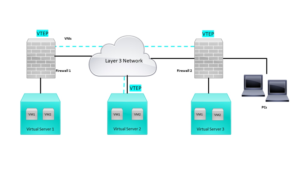 Network Topology
The configure section assumes that the underlay network is already configured on threat defense via the Secure Firewall Management Center. This document is focused on overlay network configuration.
Configure
Configure the VTEP Peer Group
Step 1: Navigate to Objects > Object Management.
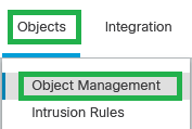 Objects - Objects Management
Step 2: Click on Network in the left menu.
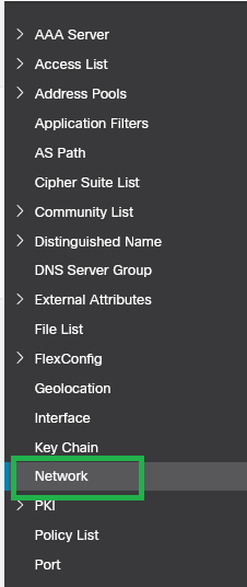 Network
Step 3: Create Network host Objects for the VTEP peer IP addresses. Click on Add Network > Add Object.
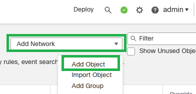 Add Network - Add Object
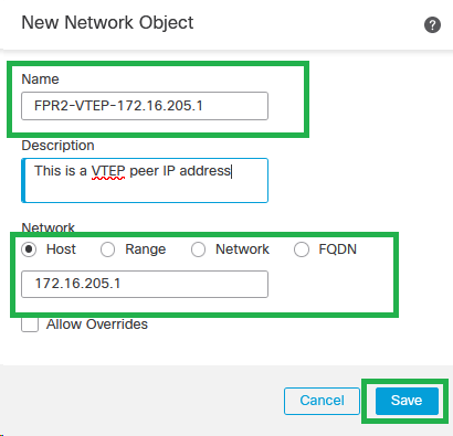
Step 4: Create a new host Network Object for the VTEP peer. Set up an object name and IP address, then click on Save.
 New Network Object

Note: Configure more host network objects for each VTEP peer IP address you have. There are two objects in this configuration guide.
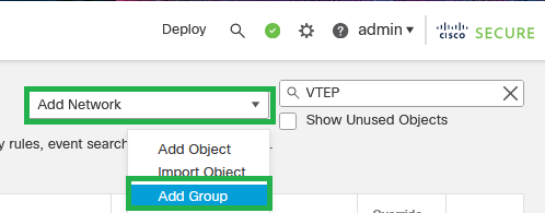
Step 5: Create Object Group, click on Add Network > Add Group.
 Add Network - Add Group
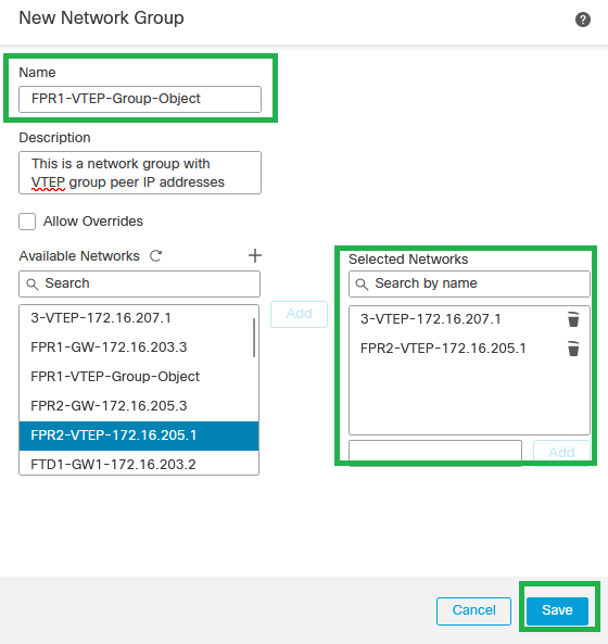
Step 6: Create the network object group with all VTEP peer IP addresses. Set up a network group name and select the network object groups required, then click on Save.
 Create Network Object Group
Step 7: Validate the network object and network object group from the Network Object filter.
 Validate the VTEP object group
Configure the VTEP source interface
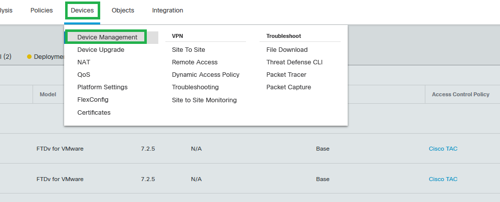
Step 1: Navigate to Devices > Device Management, and edit the threat defense.
 Devices - Device Management
Step 2: Navigate to the VTEP section.
 VTEP section
Step 3: Select the Enable VNE checkbox, and click on Add VTEP.
 Enable NVE and Add VTEP
Step 4: Choose VxLAN as the Encapsulation type, enter the Encapsulation Port value, and Choose the interface used for VTEP source on this threat defense (Outside interface for this configuration guide)
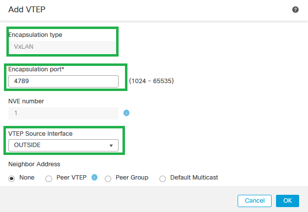 Add VTEP
Note: VxLAN encapsulation is the default one. For AWS, you can choose between VxLAN and Geneve. The default value is 4789, Any Encapsulation Port can be chosen between 1024 - 65535 range according to design.
Step 5: Select Peer Group and choose the Network Object Group created in the previous configuration section, then click OK.
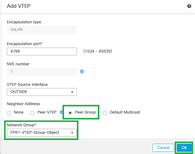 Peer Group - Network Object Group
Step 6: Save the changes.

Warning: After changes are saved, a jumbo frame change message appears, MTU is changed on the interface assigned as VTEP to 1554, ensure to use the same MTU on the underlay network.
Step 7:Click on Interfaces and edit the Interface used for the VTEP source Interface. (Outside interface on this configuration guide)
 Outside as VTEP Source Interface
Step 8 (Optional):On the General page, check the check box of NVE Only, then click OK.
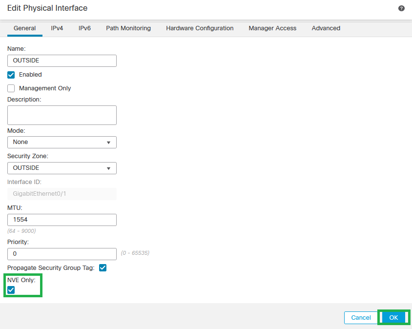 NVE Only Configuration

Warning: This setting is optional for routed mode where this setting restricts traffic to VXLAN and common management traffic only on this interface. This setting is automatically enabled for transparent firewall mode.
Step 9: Save the changes.
Configure the VTEP VNI Interface
Step 1: Navigate Devices > Device Management, and edit the threat defense.
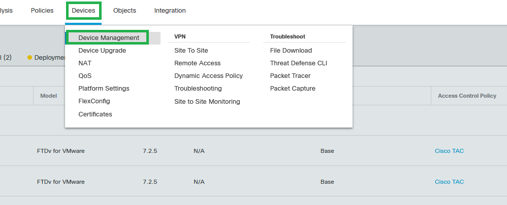 Devices - Device Management
Step 2: Under the Interfaces section, click on Add Interfaces > VNI Interfaces.
 Interfaces - Add Interfaces - VNI Interfaces
Step 3: Under the General section, set up the VNI interface with name, description, Security Zone, VNI ID, and VNI Segment ID.
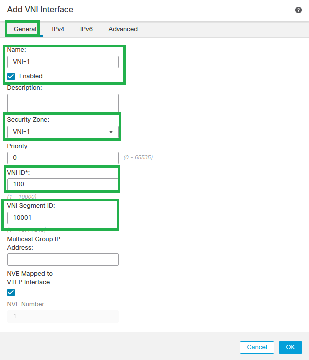 Add VNI Interface

Note: VNI ID is configured between 1 and 10000, and VNI Segment ID is configured between 1 and 16777215 (the segment ID is used for VXLAN tagging).

Caution: If the multicast group is not configured on the VNI interface, the default group from the VTEP source interface configuration is used if it is available. If you manually set a VTEP peer IP for the VTEP source interface, you cannot specify a multicast group for the VNI interface.
Step 3: Select the NVE Mapped to VTEP Interface checkbox and Click OK.
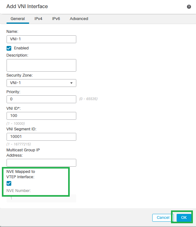 NVE Mapped to VTEP Interface
Step 4: Configure a static route to advertise the destination networks for VXLAN to the VNI peer interface. Navigate Routing > Static Route.
 Static Route Configuration

Caution: Destination networks for VXLAN must be sent via the peer VNI interface. All VNI interfaces must be on the same broadcast domain (Logical segment).
Step 5: Save and Deploy the changes.

Warning: Validation warnings can be seen before the deployment, ensure the VTEP peer IP addresses are reachable from the physical VTEP source interface.
Verify
Verify the NVE configuration.
firepower# show running-config nve
nve 1
encapsulation vxlan
source-interface OUTSIDE
peer-group FPR1-VTEP-Group-Object
firepower# show nve 1
nve 1, source-interface "OUTSIDE" is up (nve-only cluster is OFF)
IP address 172.16.203.1, subnet mask 255.255.255.0
Encapsulation: vxlan
Encapsulated traffic statistics:
1309 packets input, 128170 bytes
2009 packets output, 230006 bytes
142 packets dropped
Number of configured static peer VTEPs: 0
Configured static peer group: FPR1-VTEP-Group-Object
Configured static peer group VTEPs:
IP address 172.16.205.1 MAC address 0050.56b3.c30a (learned)
IP address 172.16.207.1 MAC address 0050.56b3.c30a (learned)
Number of discovered peer VTEPs: 1
Discovered peer VTEPs:
IP address 172.16.205.1
IP address 172.16.207.1
Number of VNIs attached to nve 1: 1
VNIs attached:
vni 100: proxy off, segment-id 10001, mcast-group none
NVE proxy single-arm channel is off.
firepower# show nve 1 summary
nve 1, source-interface "OUTSIDE" is up (nve-only cluster is OFF)
Encapsulation: vxlan
Number of configured static peer VTEPs: 0
Configured static peer group: FPR1-VTEP-Group-Object
Number of discovered peer VTEPs: 2
Number of VNIs attached to nve 1: 1
NVE proxy single-arm channel is off.
Verify the VNI interface configuration.
firepower# show run interface
interface vni100
segment-id 10001
nameif VNI-1
security-level 0
ip address 172.16.209.1 255.255.255.0
vtep-nve 1
Verify the MTU configuration on the VTEP interface.
firepower# show interface GigabitEthernet0/1
Interface GigabitEthernet0/1 "OUTSIDE", is up, line protocol is up
Hardware is net_vmxnet3, BW 10000 Mbps, DLY 10 usec
Auto-Duplex(Full-duplex), Auto-Speed(10000 Mbps)
Input flow control is unsupported, output flow control is unsupported
MAC address 0050.56b3.26b8, MTU 1554
IP address 172.16.203.1, subnet mask 255.255.255.0
---
[Output omitted]
---
Verify the static route configuration for destination networks.
firepower# show run route
route OUTSIDE 0.0.0.0 0.0.0.0 172.16.203.3 10
route VNI-1 172.16.212.0 255.255.255.0 172.16.209.2 1
route VNI-1 172.16.215.0 255.255.255.0 172.16.209.3 1

Note: Validate the VNI interfaces on all peers are configured on the same broadcast domain.
Troubleshoot
Check connectivity with VTEP peers.
Peer 1:
firepower# ping 172.16.205.1
Type escape sequence to abort.
Sending 5, 100-byte ICMP Echos to 172.16.205.1, timeout is 2 seconds:
!!!!!
Success rate is 100 percent (5/5), round-trip min/avg/max = 1/1/1 ms
Peer 2:
firepower# ping 172.16.207.1
Type escape sequence to abort.
Sending 5, 100-byte ICMP Echos to 172.16.207.1, timeout is 2 seconds:
!!!!!
Success rate is 100 percent (5/5), round-trip min/avg/max = 1/1/1 ms

Note: A VTEP peer connectivity issue can generate deployment failures on Secure FMC. Ensure to keep connectivity to all your VTEP peer configurations.
Check connectivity with VNI peers.
.
Peer 1:
firepower# ping 172.16.209.2
Type escape sequence to abort.
Sending 5, 100-byte ICMP Echos to 172.16.209.2, timeout is 2 seconds:
!!!!!
Success rate is 100 percent (5/5), round-trip min/avg/max = 1/2/10 ms
Peer 2:
firepower# ping 172.16.209.3
Type escape sequence to abort.
Sending 5, 100-byte ICMP Echos to 172.16.209.3, timeout is 2 seconds:
!!!!!
Success rate is 100 percent (5/5), round-trip min/avg/max = 1/2/10 ms
Sometimes, a wrong static route configured can generate ARP incomplete outputs. Configure a capture on the VTEP interface for VXLAN packets and download it on a pcap format, any packet analyzer tool helps to confirm if there is any issue with the routes. Ensure to use the VNI peer IP address as a gateway.
 Routing issue
Configure ASP drop captures on Secure FTD in case of any Firewall drop, check the ASP drop counter with the show asp drop command. Contact Cisco TAC for analysis.
Ensure to configure Access Control Policy Rules to allow the VXLAN UDP traffic on the VNI/VTEP interface.
Sometimes the VXLAN packets can be fragmented, ensure to change the MTU to jumbo frames on the underlay network to avoid fragmentation.
Configure capture on the Ingress/VTEP interface and download the captures on .pcap format for analysis. Packets must include the VXLAN header on the VTEP interface,
 Ping captuted with VXLAN header
 VXLAN header
Related Information


 Feedback