Introduction
This document describes how to configure Geneve encapsulation for FTDv data interfaces in AWS.
Prerequisites
Requirements
Cisco recommends that you have knowledge of these topics:
- Secure Firepower Management Center configuration deployment
- Secure Firepower Threat Defense Virtual deployed in AWS
- AWS instance EC2 virtualization.
Configuring Geneve encapsulation for Cisco Secure Firepower Threat Defense in AWS, requires FTD version 7.1 or greater.
Performance Tier License of FTDv20 or greater is also required.
You can only configure one Virtual Tunnel Endpoint (VTEP) source interface per FTDv device. The VTEP is defined as a Network Virtualization Endpoint (NVE); Geneve encapsulation for VTEP is the only natively supported NVE at the time.
You can refer to this documentation to Deploy the Threat Defense Virtual on AWS.
Components Used
The information in this document is based on these software and hardware versions:
- Secure Firepower Management Center - 7.3.0
- Secure Firepower Threat Defense - 7.3.0
- AWS c5.2xlarge (4 core/8 GB ) instance
- Performance tier license - FTDv50
The information in this document was created from the devices in a specific lab environment. All of the devices used in this document started with a cleared (default) configuration. If your network is live, ensure that you understand the potential impact of any command.
Configure
Configure Performance Tier License for FTDv
Use a supported browser to access your FMC GUI:
https://FMC_IP_Address
Navigate to Devices > Device Management:
 Device Management
Select the edit Icon for the FTDv in question:  Edit
Edit
Click Device tab, then edit configuration in the License summary:
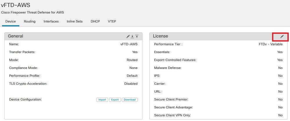 Device License
Select the FTDv20 (Core 4 / 8 GB) or greater from the Performance Tier drop-down list. For this example, FTDv50 Performance Tier License is selected as shown in this image:
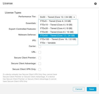 Choose Performance Tier License FTDv20 or Greater
Next, Select Save and Deploy the configuration to FTDv.
Configure the VTEP Source Interface
Navigate to Devices > Device Management > Choose edit > VTEP and select Enable NVE:
 Enable VNE
Now, you can Select Add VTEP:
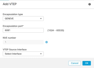 Add VTEP
Enter the value for the Encapsulation port within the specified range.

Warning: It is not recommend to change the Geneve port; AWS requires a port of 6081.
Next, you can Select the VTEP Source Interface.
 Outside Interface as VTEP Source Interface

Note: Select from the list of available physical interfaces present on the device. In case the interface Name is not displayed in the list, you can validate if the desired interface is Enabled and has a Name configured.

Caution: FMC automatically raises the MTU to 1806 bytes of the selected interface in case MTU is lower than 1806 bytes.
Next, Click OK.

Note: FMC shows Jumbo Frame is enabled:
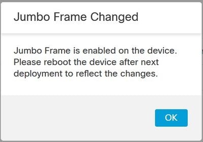 Jumbo Frame Changed
Select Ok and Save.
Configure the VNI interface
Add a Virtual Network Interface(VNI) interface, associate it with the VTEP source interface, and configure basic interface parameters.
Navigate to Interfaces Tab and click Add Interfaces.
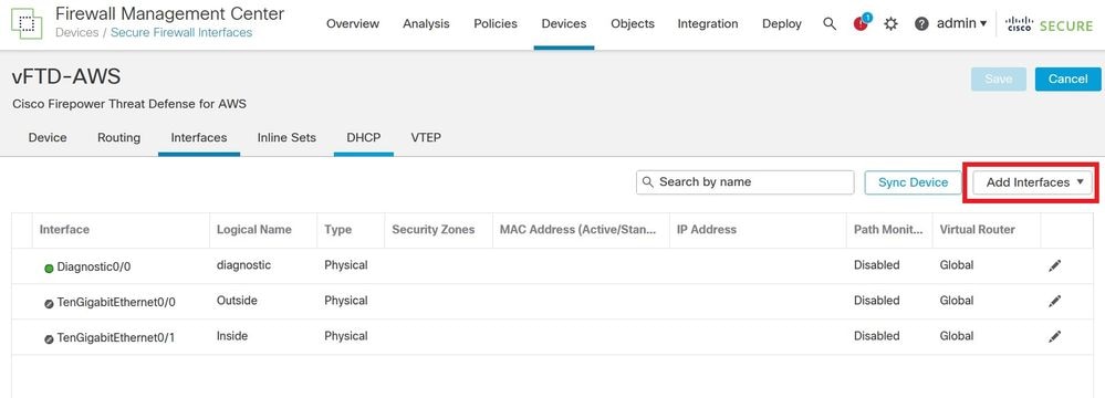 Add Interfaces
Choose VNI Interface.
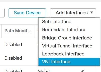 Add VNI Interface
Specify the interface Name, Description, and VNI ID (between 1 and 10000).

Tip: This ID is only an internal interface identifier.
Check Enable Proxy.
This option enables single-arm proxy, and allows traffic to exit the same interface it entered (U-turn traffic).

Warning: If you later edit the interface, you cannot disable single-arm proxy. To do that, you need to delete the existing interface and create a new VNI interface. This option is only available for a Geneve VTEP.
Select NVE Mapped to VTEP Interface. This associates this interface with the VTEP source interface.
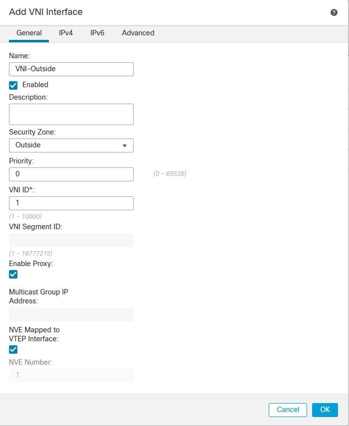 Add NVI Interface
Click OK and Save. You can see VNI interface is created as shown in this image:
 VNI Interface is Created
Finally, Deploy the interface configuration.

Note: You can configure the routed interface parameters required for your interface at this point. Interface IP address, static or Dynamic routing for VNI interface.
Verify
Connect to FTDv via SSH or console:
> system support diagnostic-cli
Attaching to Diagnostic CLI ... Press 'Ctrl+a then d' to detach.
Type help or '?' for a list of available commands.

admin> enable
Password:
admin#
Review Intreface details and VNI interface summary:
admin# show ip
System IP Addresses:
Interface                Name                   IP address      Subnet mask     Method
Management0/0            diagnostic             10.0.0.61       255.255.255.0   DHCP
vni1                     VNI-Outside            1.2.3. 4         255.255.255.0   manual
Current IP Addresses:
Interface                Name                   IP address      Subnet mask     Method
Management0/0            diagnostic             10.0.0.61       255.255.255.0   DHCP
vni1                     VNI-Outside            1.2.3. 4         255.255.255.0   manual

admin# show interface VNI summary
Interface vni1 "VNI-Outside", is up, line protocol is up
        VTEP-NVE 1
        Tag-switching: disabled
        MTU: 1500
        MAC: 0206.104e.ed0f
        proxy mode: single-arm
        IP address 1.2.3. 4, subnet mask 255.255.255.0
        Multicast group not configured
You can confirm geneve encapsulation is enabled as shown in this command output:
admin# show running-config nve
nve 1
 encapsulation geneve
 source-interface Outside
Troubleshoot
Verify bot VNI interface and VTEP source interface protocol and status are up/up. As shown next, interface TenGigabitEthernet0/0 and vni1 are up/up:
# show interface ip brief
Interface                  IP-Address      OK? Method Status                Protocol
Internal-Control0/0        127.0.1.1       YES unset  up                    up
Internal-Control0/1        unassigned      YES unset  up                    up
Internal-Data0/0           unassigned      YES unset  down                  up
Internal-Data0/0           unassigned      YES unset  up                    up
Internal-Data0/1           169.254.1.1     YES unset  up                    up
Internal-Data0/2           unassigned      YES unset  up                    up
Management0/0              10.0.0.61       YES DHCP   up                    up
TenGigabitEthernet0/0      unassigned      YES unset  up                    up
TenGigabitEthernet0/1      unassigned      YES unset  up                    up
vni1                       1.2.3. 4         YES manual up                    up
Ensure vni interface single-arm and vtep association are present as shown in this outptut:
# show run interface vni 1
!
interface vni1
 proxy single-arm
 nameif VNI-Outside
 security-level 0
 ip address 1.2.3. 4 255.255.255.0
 vtep-nve 1
Review interface counters for VNI interface:
# show interface VNI detail
Refer to the Firepower Management Center Configuration Guide for additional information.


 Feedback