Configure ECMP with IP SLA on FTD Managed by FDM
Available Languages
Download Options
Bias-Free Language
The documentation set for this product strives to use bias-free language. For the purposes of this documentation set, bias-free is defined as language that does not imply discrimination based on age, disability, gender, racial identity, ethnic identity, sexual orientation, socioeconomic status, and intersectionality. Exceptions may be present in the documentation due to language that is hardcoded in the user interfaces of the product software, language used based on RFP documentation, or language that is used by a referenced third-party product. Learn more about how Cisco is using Inclusive Language.
Contents
Introduction
This document describes how to configure ECMP along with IP SLA on a FTD that is managed by FDM.
Prerequisites
Requirements
Cisco recommends that you have knowledge of these topics:
- ECMP configuration on Cisco Secure Firewall Threat Defense (FTD)
- IP SLA configuration on Cisco Secure Firewall Threat Defense (FTD)
- Cisco Secure Firewall Device Manager (FDM)
Components Used
The information in this document is based on this software and hardware version:
- Cisco FTD version 7.4.1 (Build 172)
The information in this document was created from the devices in a specific lab environment. All of the devices used in this document started with a cleared (default) configuration. If your network is live, ensure that you understand the potential impact of any command.
Background Information
This document describes how to configure Equal-Cost Multi-Path (ECMP) along with Internet Protocol Service Level Agreement (IP SLA) on a Cisco FTD that is managed by Cisco FDM. ECMP allows you to group interfaces together on FTD and load balance traffic across multiple interfaces. IP SLA is a mechanism that monitors end to end connectivity through the exchange of regular packets. Along with ECMP, IP SLA can be implemented in order to ensure availability of the next hop. In this example, ECMP is utilized to distribute packets equally over two Internet Service Provider (ISP) circuits. At the same time, an IP SLA keeps track of connectivity, ensuring a seamless transition to any available circuits in the event of a failure.
Specific requirements for this document include:
- Access to the devices with a user account with administrator privileges
- Cisco Secure Firewall Threat Defense version 7.1 or higher
Configure
Network Diagram
In this example, Cisco FTD has two outside interfaces: outside1 and outside2 . Each one connects to an ISP gateway, outside1 and outside2 belongs to same ECMP zone named outside.
The traffic from internal network is routed through FTD and get load balanced to the internet through the two ISP.
At the same time, FTD uses IP SLAs in order to monitor connectivity to each ISP Gateway. In case of failure on any of the ISP circuit, FTD failovers to the the other ISP gateway to maintain business continuity.
 Network Diagram
Configurations
Step 0. Pre-configure Interfaces/Objects
Log into the FDM web GUI, click Device , then click the link in the Interfaces summary. The Interfaces list shows the available interfaces, their names, addresses, and states.
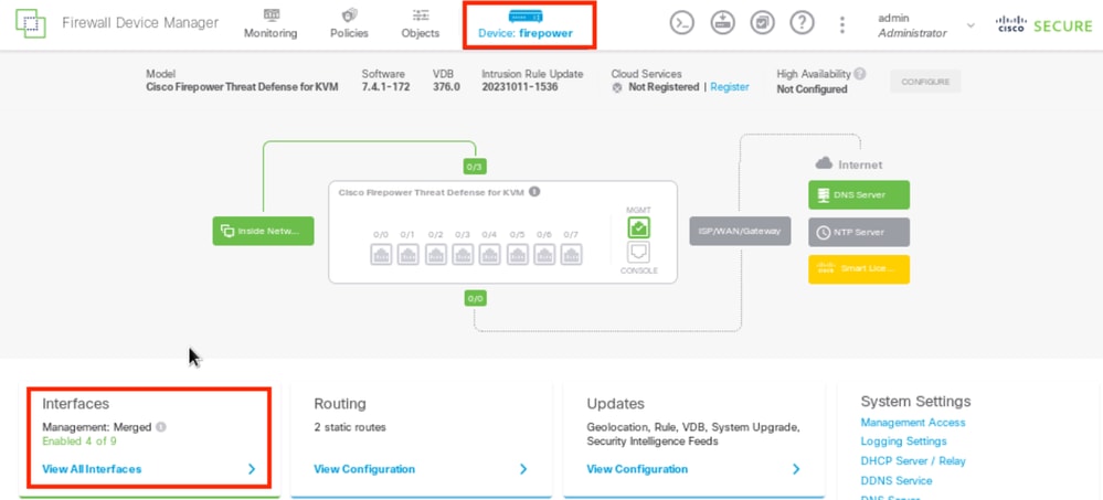 FDM Device Interface
Click the edit icon ( ) for the physical interface you want to edit. In this example GigabitEthernet0/1.
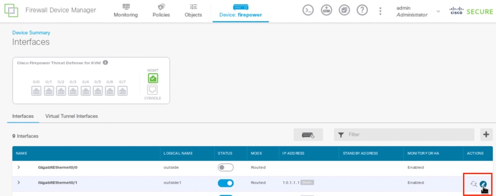 Step 0 Interface Gi0/1
In the Edit Physical Interface window:
- Set the Interface Name , in this case outside1 .
- Set the Status slider to the enabled setting (
 ).
). - Click the IPv4 Address tab and configure the IPv4 address, in this case 10.1.1.1/24.
- Click OK.
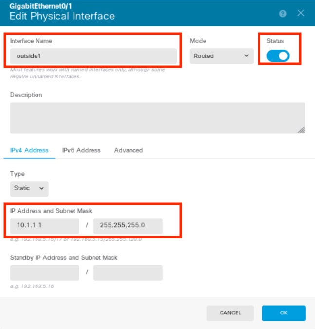 Step 0 Edit Interface Gi0/1

Note: Only routed interfaces can be associated with an ECMP zone.
Repeat the similar steps to configure the interface for the Secondary ISP connection, in this example the physical interface is GigabitEthernet0/2 . In the Edit Physical Interface window:
- Set the Interface Name , in this case outside2.
- Set the Status slider to the enabled setting (
 ).
). - Click the IPv4 Address tab and configure the IPv4 address, in this case 10.1.2.1/24.
- Click OK .
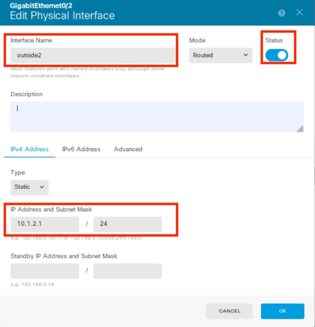 Step 0 Edit Interface Gi0/2
Repeat the similar steps to configure the interface for the inside connection, in this example the physical interface is GigabitEthernet0/3. In the Edit Physical Interface window:
- Set the Interface Name , in this case inside .
- Set the Status slider to the enabled setting (
 ).
). - Click the IPv4 Address tab and configure the IPv4 address, in this case 10.1.3.1/24.
- Click OK .
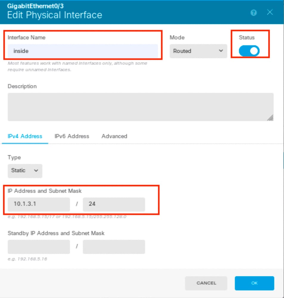 Step 0 Edit Interface Gi0/3
Navigate to Objects > Object Types > Networks , click the add icon (  ) to add new object.
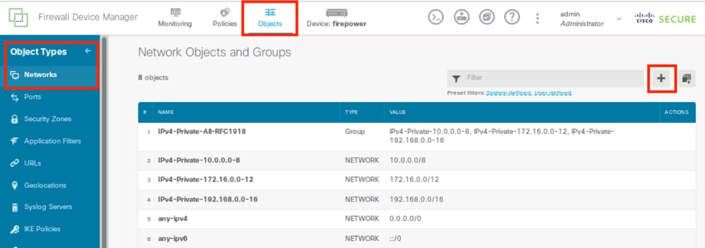 Step 0 Object1
In the Add Network Object window, configure the first ISP gateway:
- Set the Name of the object, in this case gw-outside1.
- Select the Type of the object, in this case Host.
- Set the IP address of the Host , in this case 10.1.1.2.
- Click OK .
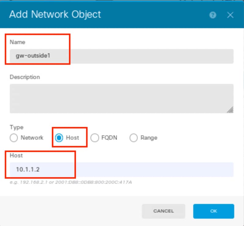 Step 0 Object2
Repeat the similar steps to configure another network object for the second ISP gateway:
- Set the Name of the object, in this case gw-outside2.
- Select the Type of the object, in this case Host.
- Set the IP address of the Host , in this case 10.1.2.2.
- Click OK .
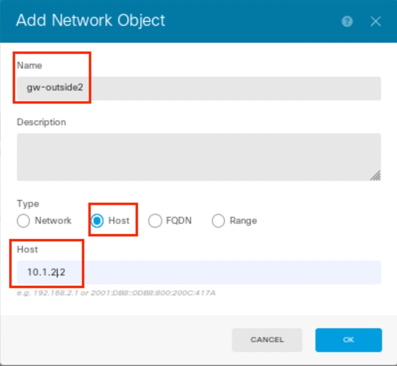 Step 0 Object3

Note: You must have your access control policy being configured on FTD to permit the traffic, this part is not included in this document.
Step 1. Configure ECMP Zone
Navigate to Device , then click the link in the Routing summary.
If you enabled virtual routers, click the view icon ( ) for the router in which you are configuring a static route. In this case virtual routers are not enabled.
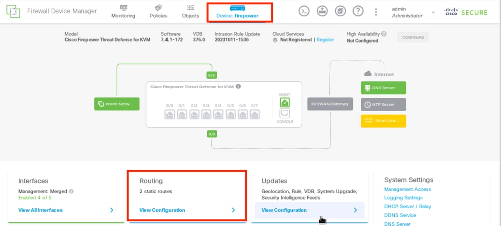 Step 1 ECMP Zone1
Click the ECMP Traffic Zones tab, then click the add icon (  ) to add a new zone.
 Step 1 ECMP Zone2
In the Add ECMP Traffic Zone window:
- Set the Name for the ECMP zone and optionally, a description.
- Click the add icon (
 ) to select up to 8 Interfaces to include in the zone. In this example, the ECMP name is Outside , interfaces outside1 and outside2 are added to the zone.
 - Click OK .
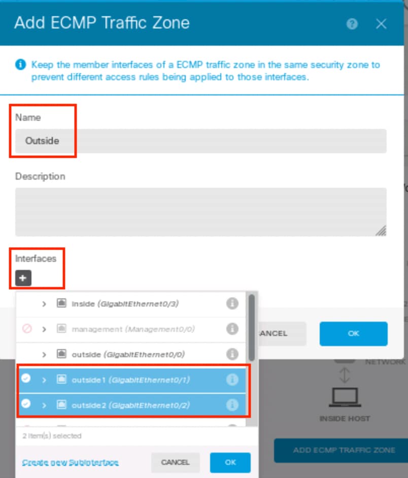 Step 1 ECMP Zone3
Both interfaces outside1 and outside2 have been added to ECMP zone outside sucessfully.
 Step 1 ECMP Zone4

Note: An ECMP routing traffic zone is not related to security zones. Creating a security zone that contains the outside1 and outside2 interfaces does not implement a traffic zone for ECMP routing purposes.
Step 2. Configure IP SLA Objects
To define the SLA objects used to monitor connectivity to each gateway, navigate to Objects > Object Types > SLA Monitors , click the add icon (  ) to add a new SLA monitor for the first ISP connection.
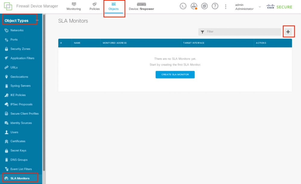 Step2 IP SLA1
In the Add SLA Monitor Object window:
- Set the Name for the SLA monitor object and optionally, a description, in this case sla-outside1.
- Set the Monitor Address , in this case gw-outside1 (the first ISP gateway).
- Set the Target Interface through which the monitor address is reachable, in this case outside1 .
- Addtionally, it is also possible to adjust the Timeout and Threshold . Click OK .
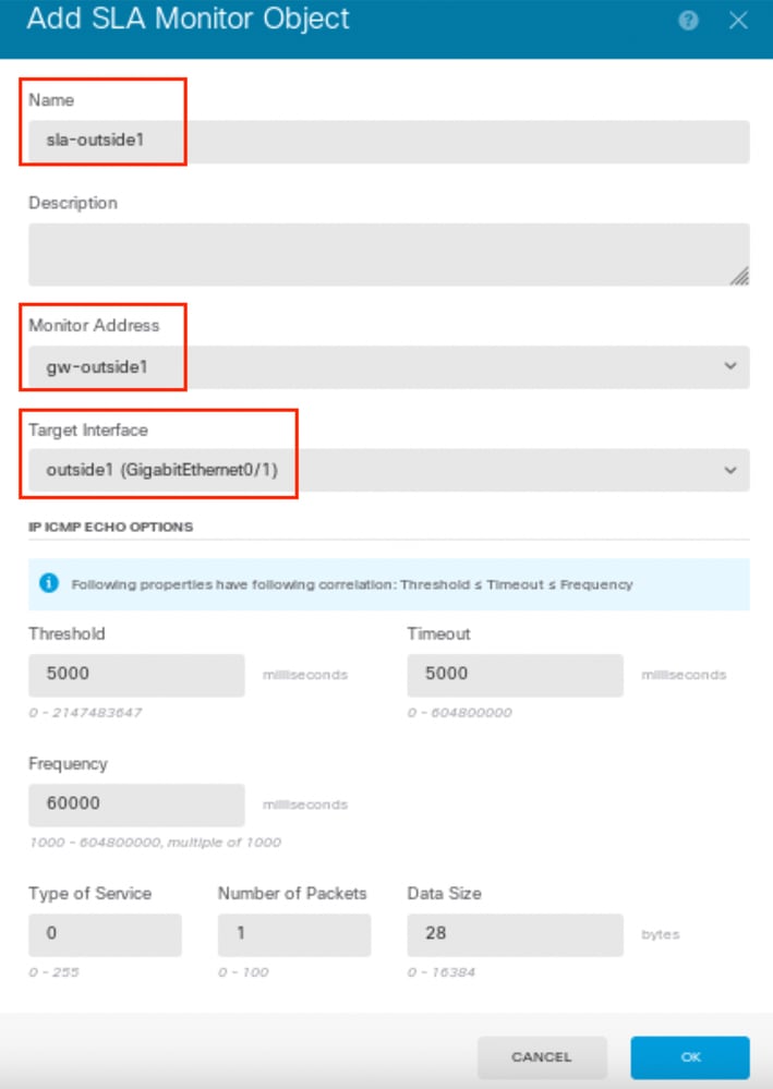 Step2 IP SLA2
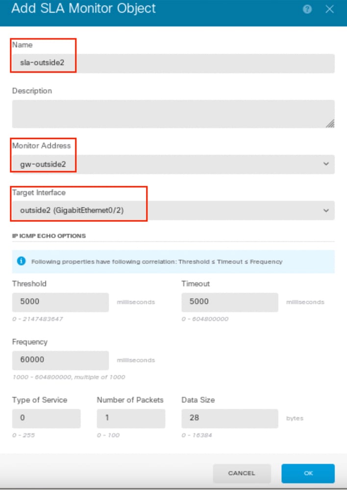
Repeat the similar step to configure another SLA Monitor Object for the second ISP connection, in the Add SLA Monitor Object window:
- Set the Name for the SLA monitor object and optionally, a description, in this case sla-outside2 .
- Set the Monitor Address , in this case gw-outside2 (the second ISP gateway).
- Set the Target Interface through which the monitor address is reachable, in this case outside2.
- Addtionally, it is also possible to adjust the Timeout and Threshold. Click OK .
 Step2 IP SLA3
Step 3. Configure Static Routes with Route Track
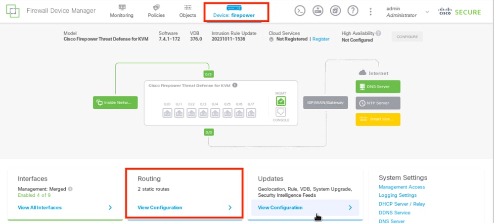
Navigate to Device , then click the link in the Routing summary.
If you enabled virtual routers, click the view icon ( ) for the router in which you are configuring a static route. In this case virtual routers are not enabled.
 Step 3 Route1
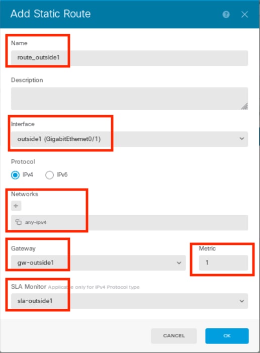
On the Static Routing page, click the add icon ( ) to add a new static route for the first ISP link.
In the Add Static Route window:
- Set the Name of the route and optionally, the description. In this case route_outside1.
- From the Interface drop-down list, select the interface through which you want to send traffic, the gateway address needs to be accessible though the interface. In this case outside1 (GigabitEthernet0/1).
- Select the Networks that identify the desination networks or hosts that use the gateway in this route. In this case the pre-defined any-ipv4.
- From the Gateway drop-down list, select the network object that identifies the IP address of the gateway, Traffic is sent to this address. In this case gw-outside1 (the first ISP gateway).
- Set the Metric of the route, between 1 and 254. In this example 1.
- From the SLA Monitor drop-down list, select the SLA monitor object. In this case sla-outside1.
- Click OK .
 Step 3 Route2
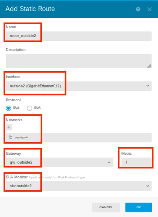
Repeat the similar step to configure another static route for the second ISP connection, in the Add Static Route window:
- Set the Name of the route and optionally, the description. In this case route_outside2.
- From the Interface drop-down list, select the interface through which you want to send traffic, the gateway address needs to be accessible though the interface. In this case outside2 (GigabitEthernet0/2).
- Select the Networks that identify the desination networks or hosts that use the gateway in this route. In this case the pre-defined any-ipv4.
- From the Gateway drop-down list, select the network object that identifies the IP address of the gateway, Traffic is sent to this address. In this case gw-outside2 (the second ISP gateway).
- Set the Metric of the route, between 1 and 254. In this example 1.
- From the SLA Monitor drop-down list, select the SLA monitor object. In this scenario, sla-outside2.
- Click OK .
 Step 3 Route3
You have 2 routes via the outside1 and outside2 interfaces with route tracks.
 Step 3 Route4
Deploy the change to FTD.
Verify
Log into the CLI of the FTD, run the command show zone to check information about ECMP traffic zones, including the interfaces that are part of each zone.
> show zone
Zone: Outside ecmp
    Security-level: 0
    Zone member(s): 2
      outside2 GigabitEthernet0/2
outside1 GigabitEthernet0/1
Run the command show running-config route to check the running configuration for the routing configuration, in this case there are two static routes with route tracks.
> show running-config route
route outside1 0.0.0.0 0.0.0.0 10.1.1.2 1 track 1
route outside2 0.0.0.0 0.0.0.0 10.1.2.2 1 track 2
Run the command show route to check the routing table, in this case there are two default routes are via the interface outside1 and outside2 with equal cost, traffic can be distributed between two ISP circuits.
> show route

Codes: L - local, C - connected, S - static, R - RIP, M - mobile, B - BGP
D - EIGRP, EX - EIGRP external, O - OSPF, IA - OSPF inter area
N1 - OSPF NSSA external type 1, N2 - OSPF NSSA external type 2
E1 - OSPF external type 1, E2 - OSPF external type 2, V - VPN
i - IS-IS, su - IS-IS summary, L1 - IS-IS level-1, L2 - IS-IS level-2
ia - IS-IS inter area, * - candidate default, U - per-user static route
o - ODR, P - periodic downloaded static route, + - replicated route
SI - Static InterVRF, BI - BGP InterVRF
Gateway of last resort is 10.1.2.2 to network 0.0.0.0

S* 0.0.0.0 0.0.0.0 [1/0] via 10.1.2.2, outside2
                   [1/0] via 10.1.1.2, outside1
C 10.1.1.0 255.255.255.0 is directly connected, outside1
L 10.1.1.1 255.255.255.255 is directly connected, outside1
C 10.1.2.0 255.255.255.0 is directly connected, outside2
L 10.1.2.1 255.255.255.255 is directly connected, outside2
C 10.1.3.0 255.255.255.0 is directly connected, inside
L 10.1.3.1 255.255.255.255 is directly connected, inside
Run the command show sla monitor configuration to check the configuration of the SLA monitor.
> show sla monitor configuration
SA Agent, Infrastructure Engine-II
Entry number: 1037119999
Owner:
Tag:
Type of operation to perform: echo
Target address: 10.1.1.2
Interface: outside1
Number of packets: 1
Request size (ARR data portion): 28
Operation timeout (milliseconds): 5000
Type Of Service parameters: 0x0
Verify data: No
Operation frequency (seconds): 60
Next Scheduled Start Time: Start Time already passed
Group Scheduled : FALSE
Life (seconds): Forever
Entry Ageout (seconds): never
Recurring (Starting Everyday): FALSE
Status of entry (SNMP RowStatus): Active
Enhanced History:

Entry number: 1631063762
Owner:
Tag:
Type of operation to perform: echo
Target address: 10.1.2.2
Interface: outside2
Number of packets: 1
Request size (ARR data portion): 28
Operation timeout (milliseconds): 5000
Type Of Service parameters: 0x0
Verify data: No
Operation frequency (seconds): 60
Next Scheduled Start Time: Start Time already passed
Group Scheduled : FALSE
Life (seconds): Forever
Entry Ageout (seconds): never
Recurring (Starting Everyday): FALSE
Status of entry (SNMP RowStatus): Active
Enhanced History:
Run the command show sla monitor operational-state to confirm the state of the SLA Monitor. In this case you can find “Timeout occurred: FALSE” in the command output, it indicates that the ICMP echo to the gateway is replying, so the default route through target interface is active and installed in routing table.
> show sla monitor operational-state
Entry number: 1037119999
Modification time: 04:14:32.771 UTC Tue Jan 30 2024
Number of Octets Used by this Entry: 2056
Number of operations attempted: 79
Number of operations skipped: 0
Current seconds left in Life: Forever
Operational state of entry: Active
Last time this entry was reset: Never
Connection loss occurred: FALSE
Timeout occurred: FALSE
Over thresholds occurred: FALSE
Latest RTT (milliseconds): 1
Latest operation start time: 05:32:32.791 UTC Tue Jan 30 2024
Latest operation return code: OK
RTT Values:
RTTAvg: 1 RTTMin: 1 RTTMax: 1
NumOfRTT: 1 RTTSum: 1 RTTSum2: 1

Entry number: 1631063762
Modification time: 04:14:32.771 UTC Tue Jan 30 2024
Number of Octets Used by this Entry: 2056
Number of operations attempted: 79
Number of operations skipped: 0
Current seconds left in Life: Forever
Operational state of entry: Active
Last time this entry was reset: Never
Connection loss occurred: FALSE
Timeout occurred: FALSE
Over thresholds occurred: FALSE
Latest RTT (milliseconds): 1
Latest operation start time: 05:32:32.791 UTC Tue Jan 30 2024
Latest operation return code: OK
RTT Values:
RTTAvg: 1 RTTMin: 1 RTTMax: 1
NumOfRTT: 1 RTTSum: 1 RTTSum2: 1
Load Balancing
Initial traffic through FTD to verify if ECMP load balance the traffic among the gateways in ECMP zone. In this case, initiate SSH connection from Test-PC-1 (10.1.3.2) and Test-PC-2 (10.1.3.4) towards Internet-Host (10.1.5.2), run the command show conn to confirm that the traffic is load-balanced between two ISP links, Test-PC-1 (10.1.3.2) goes through interface outside1, Test-PC-2 (10.1.3.4) goes through interface outside2.
> show conn
4 in use, 14 most used
Inspect Snort:
preserve-connection: 2 enabled, 0 in effect, 12 most enabled, 0 most in effect

TCP inside 10.1.3.4:41652 outside2 10.1.5.2:22, idle 0:02:10, bytes 5276, flags UIO N1
TCP inside 10.1.3.2:57484 outside1 10.1.5.2:22, idle 0:00:04, bytes 5276, flags UIO N1

Note: Traffic is load balanced among the specified gateways based on an algorithm that hashes the source and destination IP addresses, incoming interface, protocol, source and destination ports. when you run the test, the traffic you simulate can be routed to the same gateway due to the hash algorithm, this is expected, change any value among the 6 tuples (source IP, Destination IP, incoming interface, protocol, source port, destination port) to make change on the hash result.
Lost Route
If the link to the first ISP Gateway is down, in this case, shut down the first gateway router to simulate. If the FTD does not receive an echo reply from first ISP gateway within the threshold timer specified in the SLA Monitor object, the host is considered unreachable and marked as down. Tracked route to first gateway is also removed from routing table.
Run the command show sla monitor operational-state to confirm the current state of the SLA Monitor. In this case you can find “Timeout occurred: True” in the command output, it indicates that the ICMP echo to the first ISP gateway is not responding.
> show sla monitor operational-state
Entry number: 1037119999
Modification time: 04:14:32.771 UTC Tue Jan 30 2024
Number of Octets Used by this Entry: 2056
Number of operations attempted: 121
Number of operations skipped: 0
Current seconds left in Life: Forever
Operational state of entry: Active
Last time this entry was reset: Never
Connection loss occurred: FALSE
 Timeout occurred: TRUE
Over thresholds occurred: FALSE
Latest RTT (milliseconds): NoConnection/Busy/Timeout
Latest operation start time: 06:14:32.801 UTC Tue Jan 30 2024
Latest operation return code: Timeout
RTT Values:
RTTAvg: 0 RTTMin: 0 RTTMax: 0
NumOfRTT: 0 RTTSum: 0 RTTSum2: 0

Entry number: 1631063762
Modification time: 04:14:32.771 UTC Tue Jan 30 2024
Number of Octets Used by this Entry: 2056
Number of operations attempted: 121
Number of operations skipped: 0
Current seconds left in Life: Forever
Operational state of entry: Active
Last time this entry was reset: Never
Connection loss occurred: FALSE
 Timeout occurred: FALSE
Over thresholds occurred: FALSE
Latest RTT (milliseconds): 1
Latest operation start time: 06:14:32.802 UTC Tue Jan 30 2024
Latest operation return code: OK
RTT Values:
RTTAvg: 1 RTTMin: 1 RTTMax: 1
NumOfRTT: 1 RTTSum: 1 RTTSum2: 1
Run the command show route to check the current routing table, the route to the first ISP gateway through interface outside1 is removed, there is only one active default route to the second ISP gateway through interface outside2.
> show route

Codes: L - local, C - connected, S - static, R - RIP, M - mobile, B - BGP
D - EIGRP, EX - EIGRP external, O - OSPF, IA - OSPF inter area
N1 - OSPF NSSA external type 1, N2 - OSPF NSSA external type 2
E1 - OSPF external type 1, E2 - OSPF external type 2, V - VPN
i - IS-IS, su - IS-IS summary, L1 - IS-IS level-1, L2 - IS-IS level-2
ia - IS-IS inter area, * - candidate default, U - per-user static route
o - ODR, P - periodic downloaded static route, + - replicated route
SI - Static InterVRF, BI - BGP InterVRF
Gateway of last resort is 10.1.2.2 to network 0.0.0.0

S* 0.0.0.0 0.0.0.0 [1/0] via 10.1.2.2, outside2
C 10.1.1.0 255.255.255.0 is directly connected, outside1
L 10.1.1.1 255.255.255.255 is directly connected, outside1
C 10.1.2.0 255.255.255.0 is directly connected, outside2
L 10.1.2.1 255.255.255.255 is directly connected, outside2
C 10.1.3.0 255.255.255.0 is directly connected, inside
L 10.1.3.1 255.255.255.255 is directly connected, inside
Run the command show conn , you can find the two connetion are still up. SSH sessions are also active on Test-PC-1 (10.1.3.2) and Test-PC-2 (10.1.3.4) without any interruption.
> show conn
4 in use, 14 most used
Inspect Snort:
preserve-connection: 2 enabled, 0 in effect, 12 most enabled, 0 most in effect

TCP inside 10.1.3.4:41652 outside2 10.1.5.2:22, idle 0:19:29, bytes 5276, flags UIO N1
TCP inside 10.1.3.2:57484 outside1 10.1.5.2:22, idle 0:17:22, bytes 5276, flags UIO N1

Note: You can notice in the output of show conn , SSH session from Test-PC-1 (10.1.3.2) is still through interface outside1, although the default route through interface outside1 has been removed from routing table. this is expected and by design, the actual traffic flows through interface outside2. If you initiate new connection from Test-PC-1 (10.1.3.2) to Internet-Host (10.1.5.2), you can find all the traffic are through interface outside2.
Troubleshoot
In order to validate the routing table change, run command debug ip routing .
In this example, when the link to first ISP gateway is down, the route through interface outside1 is removed from routing table.
> debug ip routing
IP routing debugging is on

RT: ip_route_delete 0.0.0.0 0.0.0.0 via 10.1.1.2, outside1
ha_cluster_synced 0 routetype 0

RT: del 0.0.0.0 via 10.1.1.2, static metric [1/0]NP-route: Delete-Output 0.0.0.0/0 hop_count:1 , via 0.0.0.0, outside1

RT(mgmt-only):
NP-route: Update-Output 0.0.0.0/0 hop_count:1 , via 10.1.2.2, outside2
NP-route: Update-Input 0.0.0.0/0 hop_count:1 Distance:1 Flags:0X0 , via 10.1.2.2, outside2
Run the command show route to confirm the current routing table.
> show route

Codes: L - local, C - connected, S - static, R - RIP, M - mobile, B - BGP
D - EIGRP, EX - EIGRP external, O - OSPF, IA - OSPF inter area
N1 - OSPF NSSA external type 1, N2 - OSPF NSSA external type 2
E1 - OSPF external type 1, E2 - OSPF external type 2, V - VPN
i - IS-IS, su - IS-IS summary, L1 - IS-IS level-1, L2 - IS-IS level-2
ia - IS-IS inter area, * - candidate default, U - per-user static route
o - ODR, P - periodic downloaded static route, + - replicated route
SI - Static InterVRF, BI - BGP InterVRF
Gateway of last resort is 10.1.2.2 to network 0.0.0.0

S* 0.0.0.0 0.0.0.0 [1/0] via 10.1.2.2, outside2
C 10.1.1.0 255.255.255.0 is directly connected, outside1
L 10.1.1.1 255.255.255.255 is directly connected, outside1
C 10.1.2.0 255.255.255.0 is directly connected, outside2
L 10.1.2.1 255.255.255.255 is directly connected, outside2
C 10.1.3.0 255.255.255.0 is directly connected, inside
L 10.1.3.1 255.255.255.255 is directly connected, inside
When the link to first ISP gateway is up again, the route through interface outside1 is added back to routing table.
> debug ip routing
IP routing debugging is on

RT(mgmt-only):
 NP-route: Update-Output 0.0.0.0/0 hop_count:1 , via 10.1.2.2, outside2
 NP-route: Update-Output 0.0.0.0/0 hop_count:1 , via 10.1.1.2, outside2
NP-route: Update-Input 0.0.0.0/0 hop_count:2 Distance:1 Flags:0X0 , via 10.1.2.2, outside2
via 10.1.1.2, outside1
Run the command show route to confirm the current routing table.
> show route

Codes: L - local, C - connected, S - static, R - RIP, M - mobile, B - BGP
D - EIGRP, EX - EIGRP external, O - OSPF, IA - OSPF inter area
N1 - OSPF NSSA external type 1, N2 - OSPF NSSA external type 2
E1 - OSPF external type 1, E2 - OSPF external type 2, V - VPN
i - IS-IS, su - IS-IS summary, L1 - IS-IS level-1, L2 - IS-IS level-2
ia - IS-IS inter area, * - candidate default, U - per-user static route
o - ODR, P - periodic downloaded static route, + - replicated route
SI - Static InterVRF, BI - BGP InterVRF
Gateway of last resort is 10.1.2.2 to network 0.0.0.0

S* 0.0.0.0 0.0.0.0 [1/0] via 10.1.2.2, outside2
[1/0] via 10.1.1.2, outside1
C 10.1.1.0 255.255.255.0 is directly connected, outside1
L 10.1.1.1 255.255.255.255 is directly connected, outside1
C 10.1.2.0 255.255.255.0 is directly connected, outside2
L 10.1.2.1 255.255.255.255 is directly connected, outside2
C 10.1.3.0 255.255.255.0 is directly connected, inside
L 10.1.3.1 255.255.255.255 is directly connected, inside
Related Information
Revision History
| Revision | Publish Date | Comments |
|---|---|---|
1.0 |
02-Feb-2024 |
Initial Release |
Contributed by Cisco Engineers
- Chao FengCisco TAC Technical Leader
Contact Cisco
- Open a Support Case

- (Requires a Cisco Service Contract)
 Feedback