Troubleshoot OSPF Configuration in FTD
Available Languages
Download Options
Bias-Free Language
The documentation set for this product strives to use bias-free language. For the purposes of this documentation set, bias-free is defined as language that does not imply discrimination based on age, disability, gender, racial identity, ethnic identity, sexual orientation, socioeconomic status, and intersectionality. Exceptions may be present in the documentation due to language that is hardcoded in the user interfaces of the product software, language used based on RFP documentation, or language that is used by a referenced third-party product. Learn more about how Cisco is using Inclusive Language.
Contents
Introduction
This document describes how to verify and troubleshoot OSPF configuration on FTD devices using FMC as manager.
Prerequisites
Requirements
Cisco recommends that you have knowledge of these topics:
- Open Shortest Path First (OSPF) concepts and functionality
- Cisco Secure Firewall Management Center (FMC)
- Cisco Secure Firewall Threat Defense (FTD)
Components Used
The information in this document is based on these software and hardware versions:
- Virtual FTD 7.2.5
- Virtual FMC 7.2.5
The information in this document was created from the devices in a specific lab environment. All of the devices used in this document started with a cleared (default) configuration. If your network is live, ensure that you understand the potential impact of any command.
OSPF background
OSPF can be configured on FMC to use dynamic routing between FTD devices and other OSPF capable devices.
The FMC allows to run two OSPF processes at the same time for different set of interfaces.
Each device has a Router ID, which is like the device name in OSPF process. This is set to the lower interface IP by default, but can be customized to a different IP.
Something important to notice is that these parameters must match on neighbors to form OSPF adjacency:
- Interface belongs to same IP network
- Subnet mask
- Area
- Hello and Dead intervals
- MTU
- Area type (normal/NSSA/stub)
- Authentication
Basic configuration
This section shows the basic parameters that are configured for OSPF to start searching for adjacency with its neighbors.
1. Navigate to Devices > Device Management > Edit device
2. Click on Routing tab.
3. Click OSPF on the left menu bar.
4. Select Process 1 to enable OSPF configuration. FTD can run two simultaneous processes on different set of interfaces.
An Area Border Router (ABR) is located between two different areas, while Autonomous System Border Router (ASBR) is located between is located between devices using other routing protocols.
5. Choose the OSPF role as either Internal, ABR, ASBR, and ABR and ASBR.
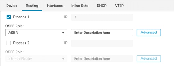 Role Selection
6. (optional) Change automatic Router ID. Select Advanced, next to OSPF role and select Router ID as IP address to customize it.
 Router ID Selection
7. Select Area > Add.
8. Enter the Area information:
- OSPF process
- Area ID
- Area Type
- Available networks
9. Click OK to save configuration.
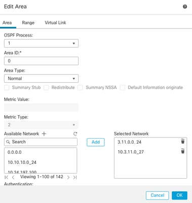 Area Selection
Redistribution
The FTD can redistribute routes from one OSPF process into another. Redistribution can also be from RIP, BGP, EIGRP (7.2+ version), static and connected routes into OSPF routing process.
1. In order to configure OSPF redistribution, navigate to Devices > Device Management > Edit device.
2. Click on Routing
3. Click on OSPF.
4. Select Redistribution > Add.
5. Enter the redistribution fields:
- OSPF process
- Route type (from where you are redistributing)
- Static
- Connected
- OSPF process
- BGP
- RIP
- EIGRP
For BGP and EIGRP, add the AS number.
6. (Optional) Select whether to use subnets.
7. Select the Metric Type.
- Type 1 uses the external metric and adds the internal cost of each hop leading to ASBR.
- Type 2 uses the external metric only.
8. Click OK to save changes.
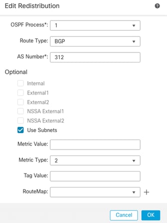 Redistribution Configuration
Filtering
You can perform an Inter-Area filtering, which restricts the routes that are sent inbound or outbound from an Area to another. This action is performed on ABRs only.
The filtering is configured with prefix-lists that are then linked to the OSPF configuration. This is an optional feature and is not needed for OSPF to work.
1. In order to configure OSPF inter-area filtering, navigate to Devices > Device Management > Edit device.
2. Click on Routing
3. Click on OSPF.
4. Select Inter-Area > Add.
5. Configure the filtering fileds:
- OSPF process
- Area ID
- Prefix list
- Traffic direction - either inbound or outbound
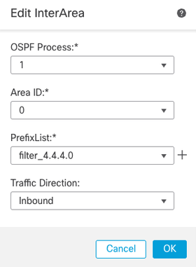 Inter-Area Filtering Configuration
6. Move to step 10 if you have prefix list configured. If you need to create a new one, you can select the plus sign or create it from Objects > Object Management > Prefix Lists > IPv4 prefix list > Add.
7. Click on Add entry.
8. Configure the prefix-list with these fields:
- Sequence number
- IP Address
- Action
- Min/Max prefix length (optional)
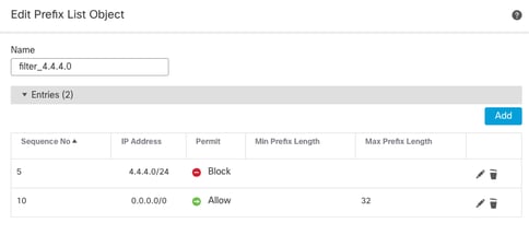 Prefix-list Object Edit
9. Click OK to save prefix-list.
10. Click OK to save Inter-Area configuration.
Interface parameters
There are certain parameters that can be modified for each interface that takes part in OSPF.
1. In order to configure OSPF interface parameters, navigate to Devices > Device Management > Edit device.
2. Click on Routing
3. Click on OSPF.
4. Select Interface > Add.
5. Select the parameters to modify
Hello and Dead timers
OSPF Hello packets are sent to maintain adjacency between devices. These packets are sent at an interval that can be configured. If the device does not receive hello packets from a neighbor within dead interval, also configurable, the neighbor changes to down state.
The hello interval by default is 10 seconds and dead interval is four times the hello interval, 40 seconds. These intervals must match between neighbors.
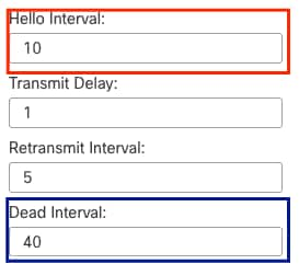 Timers Configuration
MTU Ignore-OSPF
The MTU ignore check box is an option to avoid OSPF adjacency to be stuck in EXSTART state due to MTU mismatch between neighbor interfaces. MTU match is verified because in that state, DBD are sent between neighbors and a difference in size can create issues. The best practice, however, is to keep this option unchecked.
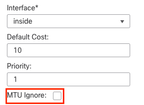 MTU Ignore Check Config
Authentication
You can select three different types of interface OSPF authentication. By default, authentication is not enabled.
- None
- Password - clear text password
- MD5 - Uses MD5 hashing
The recommendation is to use MD5 as authentication, since it is a hashing algorithm that provides security.
Configure MD5 ID and MD5 key and click OK to save.
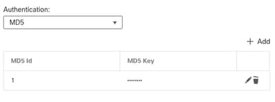 MD5 Key Configuration
The MD5 key or password must match on the interface parameters of the neighbor that is authenticated.
General CLI Verification
Example Topology
Consider this network topology as an example:
 Network Topology Example
Take into account these considerations:
- OSPF is configured on External FTD, Internal FTD and Internal Router.
- External FTD is selected as ASBR role, Internal FTD as ABR and Internal Router as Internal role.
- Area 0 is created between External and Internal FTD, while Area 1 is created between Internal FTD and Internal Router.
- External FTD is also performing BGP neighborship with another device.
- The BGP routes learned by Autonomous System 312 are redistributed into OSPF.
- MTU and intervals are configured with default values.
- Internal FTD is filtering inbound inter-area routes to Area 0 learned from Internal Router.
- Interface authentication is configured as MD5 on all devices taking part in OSPF.
Internal FTD
The configuration of Internal FTD is shown like this:
Interface configuration using MD5 authentication
interface GigabitEthernet0/0
nameif inside
security-level 0
ip address 10.6.11.1 255.255.255.0
ospf message-digest-key 1 md5 *****
ospf authentication message-digest
!
interface GigabitEthernet0/1
nameif outside
security-level 0
ip address 10.3.11.2 255.255.255.0
ospf message-digest-key 1 md5 *****
ospf authentication message-digest
!
OSPF configuration states that network 10.3.11.0/24 is advertised to area 0 and network 10.6.11.0/24 is advertised to neighbors on area 1.
The inter-area filtering is applying a prefix-list to inbound routes entering area 0. In this prefix-list, the network 192.168.4.0 from Internal Router is denied and everything else permitted.
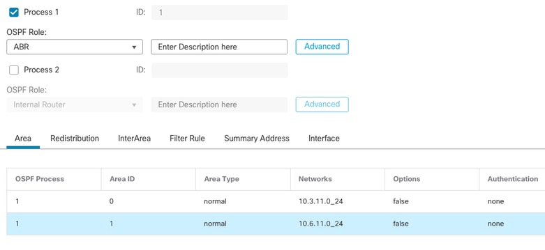 Internal FTD Area Configuration
 Internal FTD Filtering Configuration
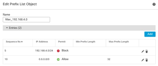 Internal FTD Prefix-list
router ospf 1
network 10.3.11.0 255.255.255.0 area 0
network 10.6.11.0 255.255.255.0 area 1
area 0 filter-list prefix filter_192.168.4.0 in
log-adj-changes

prefix-list filter_192.168.4.0 seq 5 deny 192.168.4.0/24
prefix-list filter_192.168.4.0 seq 10 permit 0.0.0.0/0 le 32
External FTD
The configuration of External FTD is shown like this in CLI:
Interface configuration using MD5 authentication.
interface GigabitEthernet0/0
nameif inside
security-level 0
ip address 10.3.11.1 255.255.255.0
ospf message-digest-key 1 md5 *****
ospf authentication message-digest
!
interface GigabitEthernet0/1
nameif outside
security-level 0
ip address 172.16.11.1 255.255.255.0
!
OSPF configuration shows that route 10.3.11.0/24 is advertised to Internal FTD in Area 0.
The BGP redistribution into OSPF can also be observed.
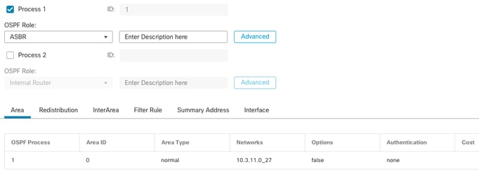 External FTD Area Configuration
 External FTD Redistribution Configuration
router ospf 1
network 10.3.11.0 255.255.255.0 area 0
log-adj-changes
redistribute bgp 312 subnets
Troubleshooting Commands
There are several commands that are useful to determine whether OSPF is working as expected.

Note: These commands are not shown on show tech files when FTD Troubleshooting files are generated apart from OSPF configuration and need to be entered manually from FTD CLI.
show running-config router
This command shows the configuration of the dynamic routing protocols, not only OSPF.
Useful to check OSPF related configuration in the CLI.
show route
The show route output states important information about the current available routes.
- A route learned through OSPF is shown with the letter O.
- An inter-area route is shown with the letters O IA.
- A route that is learned from another routing protocol through redistribution shows letters O E1 or O E2, depending on the metric type selected.
show route output from Internal FTD shows that there are three external routes known from ASBR neighbor 10.3.11.1.
It also shows network 192.168.4.0/24 learned from neighbor 10.6.11.2 on its same area.
Internal-FTD# show route

Codes: L - local, C - connected, S - static, R - RIP, M - mobile, B - BGP
       D - EIGRP, EX - EIGRP external, O - OSPF, IA - OSPF inter area
       N1 - OSPF NSSA external type 1, N2 - OSPF NSSA external type 2
       E1 - OSPF external type 1, E2 - OSPF external type 2, V - VPN
       i - IS-IS, su - IS-IS summary, L1 - IS-IS level-1, L2 - IS-IS level-2
       ia - IS-IS inter area, * - candidate default, U - per-user static route
       o - ODR, P - periodic downloaded static route, + - replicated route
       SI - Static InterVRF
Gateway of last resort is not set

C        10.3.11.0 255.255.255.0 is directly connected, outside
L        10.3.11.2 255.255.255.255 is directly connected, outside
O E2     10.5.11.0 255.255.255.224 [110/1] via 10.3.11.1, 6w5d, outside
O E2     10.5.11.32 255.255.255.224 [110/1] via 10.3.11.1, 6w5d, outside
O E2     10.5.11.64 255.255.255.224 [110/1] via 10.3.11.1, 6w5d, outside
C        10.6.11.0 255.255.255.0 is directly connected, inside
L        10.6.11.1 255.255.255.255 is directly connected, inside
O        192.168.4.0 255.255.255.0 [110/20] via 10.6.11.2, 02:19:24, inside
From External FTD, it can be observed that route 10.6.11.0/24 is known from neighbor 10.3.11.2 and it belongs to a different area.
The route 192.168.4.0/24 is not observed in this output because it was filtered on Internal FTD.
Furthermore, there are three BGP routes learned from another device that are redistributed into OSPF as External type 2 routes as seen in Internal FTD.
External-FTD# show route

Codes: L - local, C - connected, S - static, R - RIP, M - mobile, B - BGP
       D - EIGRP, EX - EIGRP external, O - OSPF, IA - OSPF inter area
       N1 - OSPF NSSA external type 1, N2 - OSPF NSSA external type 2
       E1 - OSPF external type 1, E2 - OSPF external type 2, V - VPN
       i - IS-IS, su - IS-IS summary, L1 - IS-IS level-1, L2 - IS-IS level-2
       ia - IS-IS inter area, * - candidate default, U - per-user static route
       o - ODR, P - periodic downloaded static route, + - replicated route
       SI - Static InterVRF, BI - BGP InterVRF
Gateway of last resort is not set

C        10.3.11.0 255.255.255.0 is directly connected, inside
L        10.3.11.1 255.255.255.255 is directly connected, inside
B        10.5.11.0 255.255.255.224 [20/0] via 172.16.11.2, 6w5d
B        10.5.11.32 255.255.255.224 [20/0] via 172.16.11.2, 6w5d
B        10.5.11.64 255.255.255.224 [20/0] via 172.16.11.2, 6w5d
O IA     10.6.11.0 255.255.255.0 [110/20] via 10.3.11.2, 02:03:27, inside
C        172.16.11.0 255.255.255.0 is directly connected, outside
L        172.16.11.1 255.255.255.255 is directly connected, outside
show ospf neighbor
This command helps to verify what is the state of the OSPF adjacency and whether that neighbor is a Designated Router (DR), a Backup Designated Router (BDR) or other (DROTHER).
The DR is the device that updates the rest of devices in the same subnet whenever there is a change on the network. BDR takes the DR role if this is no longer available.
This is also useful as it shows the Router ID of the neighbors, as well as the IP address and the interface from which the neighbor is known.
The Dead time countdown is observed as well. If you have the default timers, you can see the time go down from 00:40 to 00:30 before a new hello packet is sent and timer is restarted.
If this time goes all the way to zero, the adjacency is lost.
In this example, Internal FTD output shows that this device is a BDR in FULL state with each of its two neighbors, which in return are DRs, reachable from each interface. Their Router IDs are 10.3.11.1 and 192.168.4.1 respectively.
Internal-FTD# show ospf neighbor

Neighbor ID     Pri   State           Dead Time   Address         Interface
10.3.11.1         1   FULL/DR         0:00:38    10.3.11.1       outside
192.168.4.1       1   FULL/DR         0:00:33    10.6.11.2       inside
show ospf interface
The show ospf interface output shows detailed information and provides a broader vision of the OSPF process on each configured interface.
These are some of the parameters visible with this output:
- OSPF Process ID
- Router ID
- Metric (cost)
- State - DR, BDR or DROTHER
- Who is DR and BDR
- Hellos and Dead timer intervals
- Neighbor summary
- Authentication details
In the next output from Internal FTD, it can be observed that this device is indeed the BDR on both interfaces and that neighbor matches with the information from show ospf neighbors.
Internal-FTD#show ospf interface

outside is up, line protocol is up
Internet Address 10.3.11.2 mask 255.255.255.0, Area 0
Process ID 1, Router ID 10.6.11.1, Network Type BROADCAST, Cost: 10
Transmit Delay is 1 sec, State BDR, Priority 1
Designated Router (ID) 10.3.11.1, Interface address 10.3.11.1
Backup Designated router (ID) 10.6.11.1, Interface address 10.3.11.2
Timer intervals configured, Hello 10, Dead 40, Wait 40, Retransmit 5
oob-resync timeout 40
Hello due in 0:00:04
Supports Link-local Signaling (LLS)
Cisco NSF helper support enabled
IETF NSF helper support enabled
Index 1/1, flood queue length 0
Next 0x0(0)/0x0(0)
Last flood scan length is 1, maximum is 2
Last flood scan time is 0 msec, maximum is 0 msec
Neighbor Count is 1, Adjacent neighbor count is 1
Adjacent with neighbor 10.3.11.1 (Designated Router)
Suppress hello for 0 neighbor(s)
Cryptographic authentication enabled
Youngest key id is 1

inside is up, line protocol is up
Internet Address 10.6.11.1 mask 255.255.255.0, Area 1
Process ID 1, Router ID 10.6.11.1, Network Type BROADCAST, Cost: 10
Transmit Delay is 1 sec, State BDR, Priority 1
Designated Router (ID) 192.168.4.1, Interface address 10.6.11.2
Backup Designated router (ID) 10.6.11.1, Interface address 10.6.11.1
Timer intervals configured, Hello 10, Dead 40, Wait 40, Retransmit 5
oob-resync timeout 40
Hello due in 0:00:03
Supports Link-local Signaling (LLS)
Cisco NSF helper support enabled
IETF NSF helper support enabled
Index 1/2, flood queue length 0
Next 0x0(0)/0x0(0)
Last flood scan length is 1, maximum is 2
Last flood scan time is 0 msec, maximum is 0 msec
Neighbor Count is 1, Adjacent neighbor count is 1
Adjacent with neighbor 192.168.4.1 (Designated Router)
Suppress hello for 0 neighbor(s)
Cryptographic authentication enabled
Youngest key id is 1
show ospf database
This command has further information of the Link State Advertisement (LSA) Types of OSPF. The output is complex and is helpful for a deeper troubleshoot only.
LSA is the way that OSPF exchanges information and updates between devices, instead of sending the complete routing table.
The most common LSA Types are:
Type 1 - Router Link States - The router IDs of the Advertising routers
Type 2 - Network Link States - The interfaces connected in the same link as the Designated Router.
Type 3 - Summary Network Link States - Inter-area routes injected into this area by Area Border Router (ABR).
Type 4 - Summary ASB Link States - The router IDs of the Autonomous System Border Router (ASBR).
Type 5 - AS External Link States - External routes learned from ASBRs.
With this in mind, the output from this command can be interpreted from Internal FTD example.
- The databases are shown per Area.
- Link ID column contains the important information to notice.
- As mentioned before, Type 1 shows the router IDs of each device in the area and Type 2 shows the DR of each subnet link. In this case, 10.3.11.1 for Area 0 and 10.6.11.2 for Area 1.
- Type 3 shows inter-area routes injected into the respective area by ABR. 10.6.11.0 for Area 0 and 10.3.11.0 for Area 1.
- Type 4 shows the Router ID of the ASBR. Area 1 sees that 10.3.11.1 device is the ASBR of the process.
- Type 5 shows the routes redistributed by the ASBR. In this case, three external routes: 10.5.11.0, 10.5.11.32 and 10.5.11.64.
Internal-FTD# show ospf database


            OSPF Router with ID (10.6.11.1) (Process ID 1)

                Router Link States (Area 0)

Link ID         ADV Router      Age         Seq#       Checksum Link count
10.3.11.1       10.3.11.1       234         0x8000002b 0x4c4d 1
10.6.11.1       10.6.11.1       187         0x8000002e 0x157b 1

                Net Link States (Area 0)

Link ID         ADV Router      Age         Seq#       Checksum
10.3.11.1       10.3.11.1       234         0x80000029 0x7f2b

                Summary Net Link States (Area 0)

Link ID         ADV Router      Age         Seq#       Checksum
10.6.11.0       10.6.11.1       187         0x8000002a 0x7959

                Router Link States (Area 1)

Link ID         ADV Router      Age         Seq#       Checksum Link count
10.6.11.1       10.6.11.1       187         0x8000002c 0x513b 1
192.168.4.1     192.168.4.1     1758        0x8000002a 0x70f1 2

                Net Link States (Area 1)

Link ID         ADV Router      Age         Seq#       Checksum
10.6.11.2       192.168.4.1     1759        0x80000028 0xd725

                Summary Net Link States (Area 1)

Link ID         ADV Router      Age         Seq#       Checksum
10.3.11.0       10.6.11.1       189         0x80000029 0x9f37

                Summary ASB Link States (Area 1)

Link ID         ADV Router      Age         Seq#       Checksum
10.3.11.1       10.6.11.1       189         0x80000029 0x874d

                Type-5 AS External Link States

Link ID         ADV Router      Age         Seq#       Checksum Tag
10.5.11.0       10.3.11.1       1726        0x80000028 0x152b 311
10.5.11.32      10.3.11.1       1726        0x80000028 0xd34c 311
10.5.11.64      10.3.11.1       1726        0x80000028 0x926d 311
Related Information
Revision History
| Revision | Publish Date | Comments |
|---|---|---|
1.0 |
14-Feb-2024 |
Initial Release |
Contributed by Cisco Engineers
- Jorge Daniel Juarez Ruiz
Contact Cisco
- Open a Support Case

- (Requires a Cisco Service Contract)
 Feedback