Configure BGP over Route-Based VPN on FTD Managed by FDM
Available Languages
Download Options
Bias-Free Language
The documentation set for this product strives to use bias-free language. For the purposes of this documentation set, bias-free is defined as language that does not imply discrimination based on age, disability, gender, racial identity, ethnic identity, sexual orientation, socioeconomic status, and intersectionality. Exceptions may be present in the documentation due to language that is hardcoded in the user interfaces of the product software, language used based on RFP documentation, or language that is used by a referenced third-party product. Learn more about how Cisco is using Inclusive Language.
Introduction
This document describes configuring BGP over route-based site-to-site VPN on FTDv managed by FirePower Device Manager (FDM).
Prerequisites
Requirements
Cisco recommends that you have knowledge of these topics:
- Basic understanding of VPN
- BGP configurations on FTDv
- Experience with FDM
Components Used
The information in this document is based on these software and hardware versions:
- Cisco FTDv version 7.4.2
- Cisco FDM version 7.4.2
The information in this document was created from the devices in a specific lab environment. All of the devices used in this document started with a cleared (default) configuration. If your network is live, ensure that you understand the potential impact of any command.
Configure
Network Diagram
 Topo
Topo
Configurations on VPN
Step 1. Ensure the IP interconnectivity between nodes is ready and stable. The smart license on FDM is registered with the smart account successfully.
Step 2. The gateway of Site1 Client is configured with the inside IP address of Site1 FTD (192.168.70.1). The gateway of the Site2 client is configured with the inside IP address of Site2 FTD (192.168.50.1). Also, ensure the default route on both FTDs is configured correctly after FDM initialization.
Login to the GUI of each FDM. Navigate to Device > Routing . Click View Configuration . Click the Static Routing tab in order to verify the default static route.
 Site1_FTD_Gateway
 Site2_FTD_Gateway
Step 3. Configure route-based site-to-site VPN. In this example, first configure the Site1 FTD.
Step 3.1. Login to the FDM GUI of Site1 FTD. Create a new network object for the inside network of Site1 FTD. Navigate to Objects > Networks, click the + button.
 Create_Network_Object
Step 3.2. Provide necessary information. Click the OK button.
- Name: inside_192.168.70.0
- Type: Network
- Network: 192.168.70.0/24
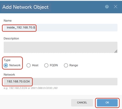 Site1_Inside_Network
Step 3.3. Navigate to Device > Site-to-Site VPN . Click View Configuration .
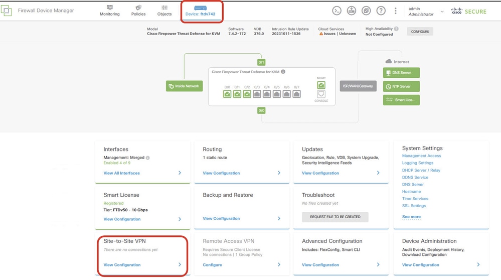 View Site-to-Site VPN
Step 3.4. Start to create a new site-to-site VPN. Click CREATE SITE-TO-SITE CONNECTION .
 Create_Site-to-Site_Connection
Step 3.5. Provide the necessary information.
- Connection Profile Name: Demo_S2S
- Type: Route Based (VTI)
- Local VPN Access Interface: click the dropdown list, then click
Create new Virtual Tunnel Interface.
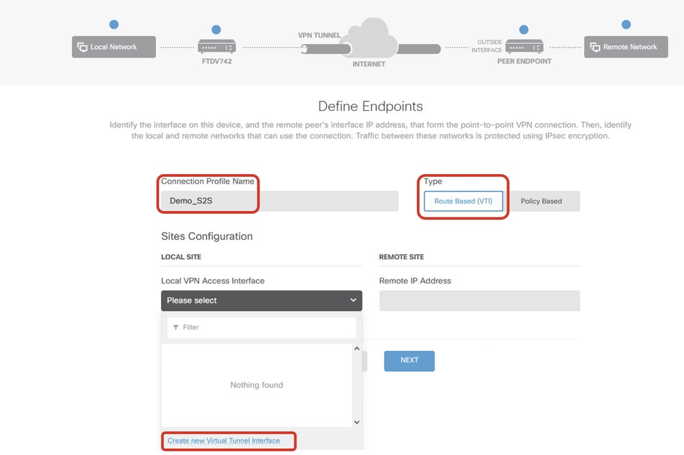 Create_VTI_in_VPN_Wizard
Step 3.6. Provide the necessary information in order to create a new VTI. Click the OK button.
- Name: demovti
- Tunnel ID: 1
- Tunnel Source: outside (GigabitEthernet0/0)
- IP Address And Subnet Mask: 169.254.10.1/24
- Status: click the slider to the Enabled position
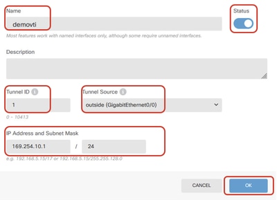 Create_VTI_Details
Step 3.7. Continue to provide the necessary information. Click the NEXT button.
- Local VPN Access Interface: demovti (created in Step 3.6.)
- Remote IP Address: 192.168.10.1
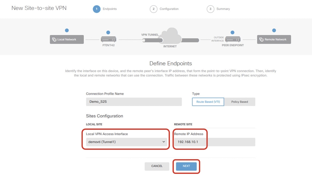 VPN_Wizard_Endpoints_Step1
Step 3.8. Navigate to IKE Policy. Click the EDIT button.
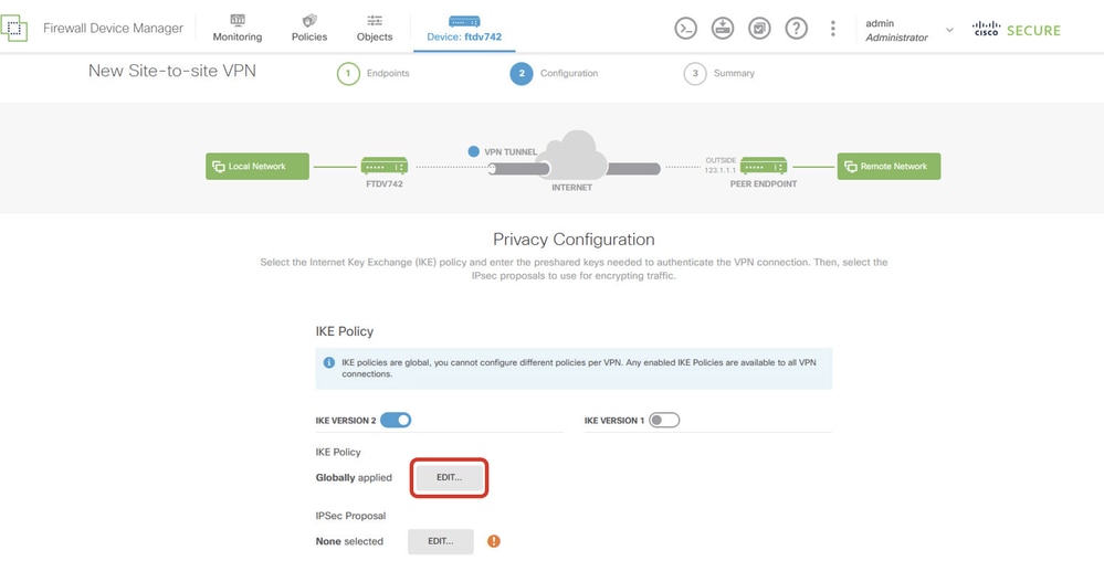 Edit_IKE_Policy
Step 3.9. For the IKE policy, you can use a pre-defined one or create a new one by clicking Create New IKE Policy.
In this example, toggle an existing IKE policy AES-SHA-SHA and also create a new one for demo purposes. Click the OK button in order to save.
- Name: AES256_DH14_SHA256_SHA256
- Encryption: AES, AES256
- DH Group: 14
- Integrity Hash: SHA, SHA256
- PRF Hash: SHA, SHA256
- Lifetime: 86400 (default)
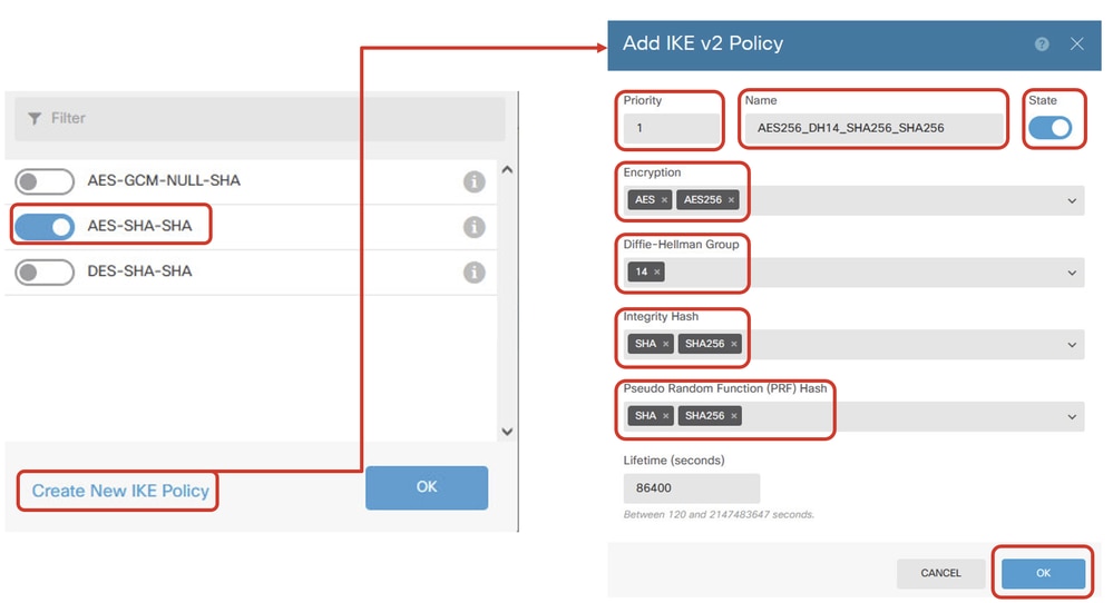 Add_New_IKE_Policy
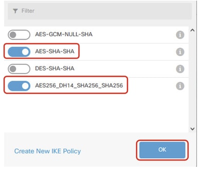 Enable_New_IKE_Policy
Step 3.10. Navigate to the IPSec Proposal. Click the EDIT button.
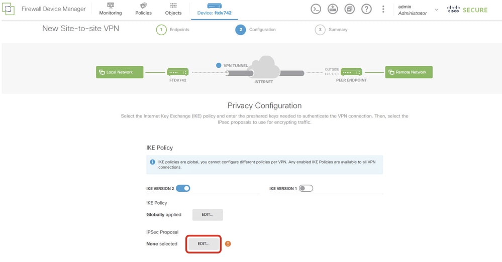 Edit_IKE_Proposal
Step 3.11. For the IPSec proposal, you can use a pre-defined or you can create a new one by clicking Create new IPSec Proposal. In this example, create a new one for demo purposes. Provide the necessary information. Click the OK button in order to save.
- Name: AES256_SHA256
- Encryption: AES, AES256
- Integrity Hash: SHA1, SHA256
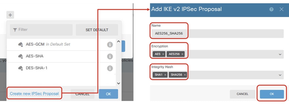 Add_New_IPSec_Proposal
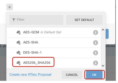 Enable_New_IPSec_Proposal
Step 3.12. Configure the pre-shared key. Click the NEXT button.
Note down this pre-shared key and configure it on the Site2 FTD later.
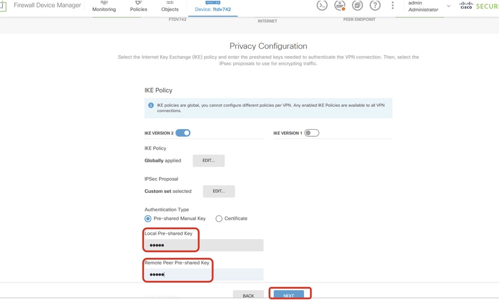 Configure_Pre_Shared_Key
Step 3.13. Review the VPN configuration. If anything needs to be modified, click the BACK button. If everything is good, click the FINISH button.
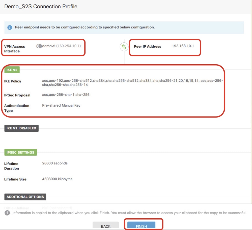 VPN_Wizard_Complete
Step 3.14. Create an Access Control rule in order to allow traffic to pass through the FTD. In this example, allow all for demo purposes. Modify your policy based on your actual needs.
 Access_Control_Rule_Example
Step 3.15. (Optional) Configure NAT exempt rule for the client traffic on FTD if dynamic NAT is configured for the client in order to access the internet. In this example, there is no need to configure a NAT-exempt rule because no dynamic NAT is configured on each FTD.
Step 3.16. Deploy the configuration changes.
 Deploy_VPN_Configuration
Configurations on BGP
Step 4. Navigate to Device > Routing. Click View Configuration.
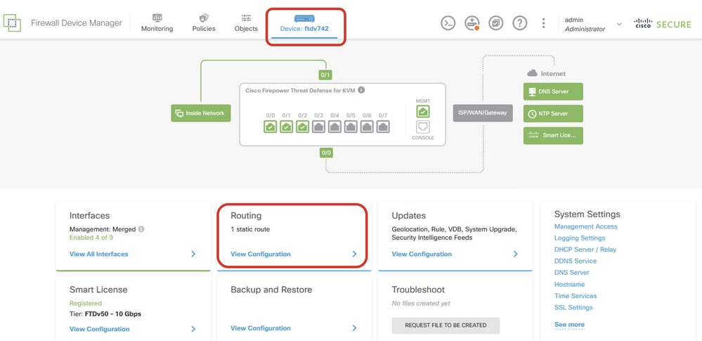 View_Routing_Configuration
Step 5. Click the BGP tab and then click CREATE BGP OBJECT.
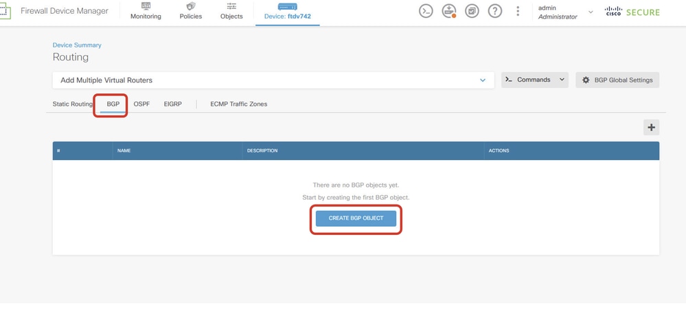 Create_BGP_Object
Step 6. Provide the name of the object. Navigate to Template and configure. Click the OK button to save.
Name: demobgp
Line 1: Configure AS number. Click as-number. Manual input local AS number. In this example, AS number 65511 for Site1 FTD.
Line 2: Configure IP protocol. Click ip-protocol. Select ipv4.
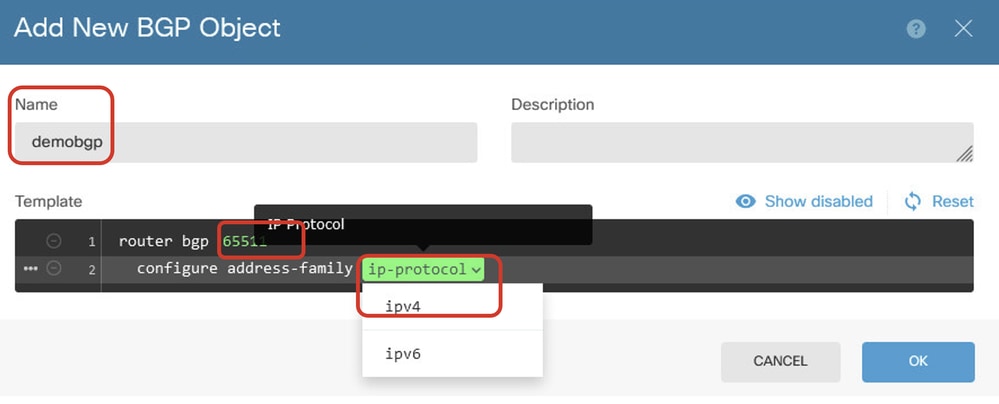 Create_BGP_Object_ASNumber_Protocol
Line 4: Configure more settings. Click settings, choose general, and then click Show disabled.
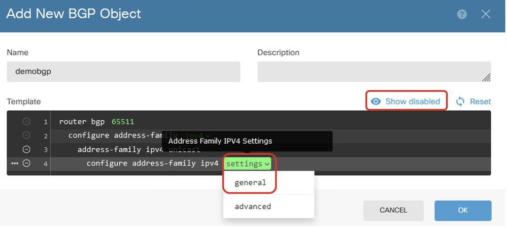 Create_BGP_Object_AddressSetting
Line 6: Click the + icon in order to enable the line to configure the BGP network. Click network-object. You can see the existing available objects and choose one. In this example, choose the object name inside_192.168.70.0 (created in Step 3.2.).
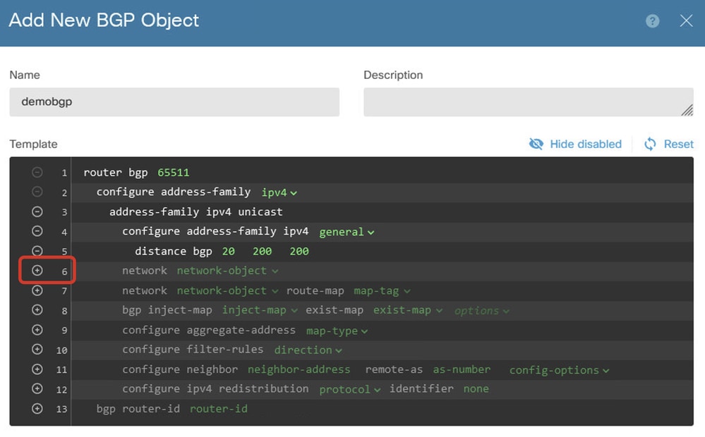 Create_BGP_Object_Add_Network
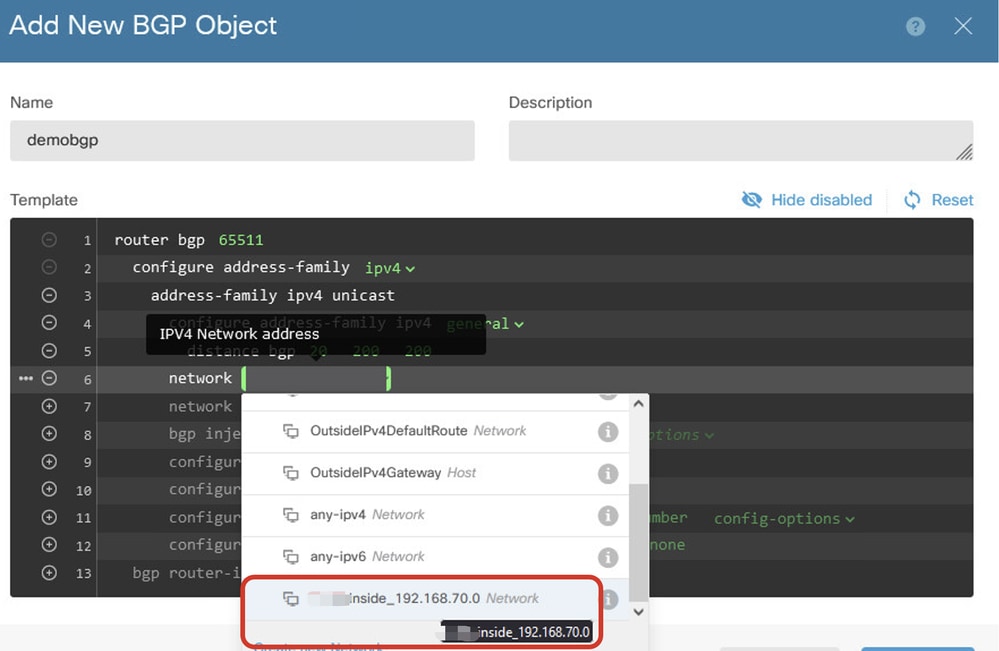 Create_BGP_Object_Add_Network2
Line 11: Click the + icon in order to enable the line to configure the BGP neighbor-related information. Click neighbor-address, and manually input the peer BGP neighbor address. In this example, it is 169.254.10.2 (VTI IP address of Site2 FTD). Click as-number, and manually input the peer AS number. In this example, 65510 is for Site2 FTD. Click config-options and choose properties.
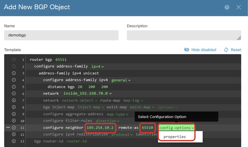 Create_BGP_Object_NeighborSetting
Line 14: Click the + icon in order to enable the line to configure some properties of the neighbor. Click activate-options and choose properties.
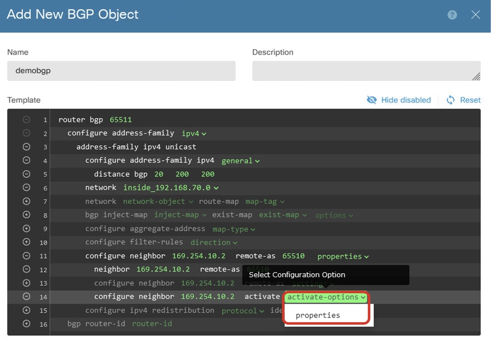 Create_BGP_Object_NeighborSetting_Properties
Line 13: Click the + icon in order to enable the line to show advanced options. Click settings and choose advanced.
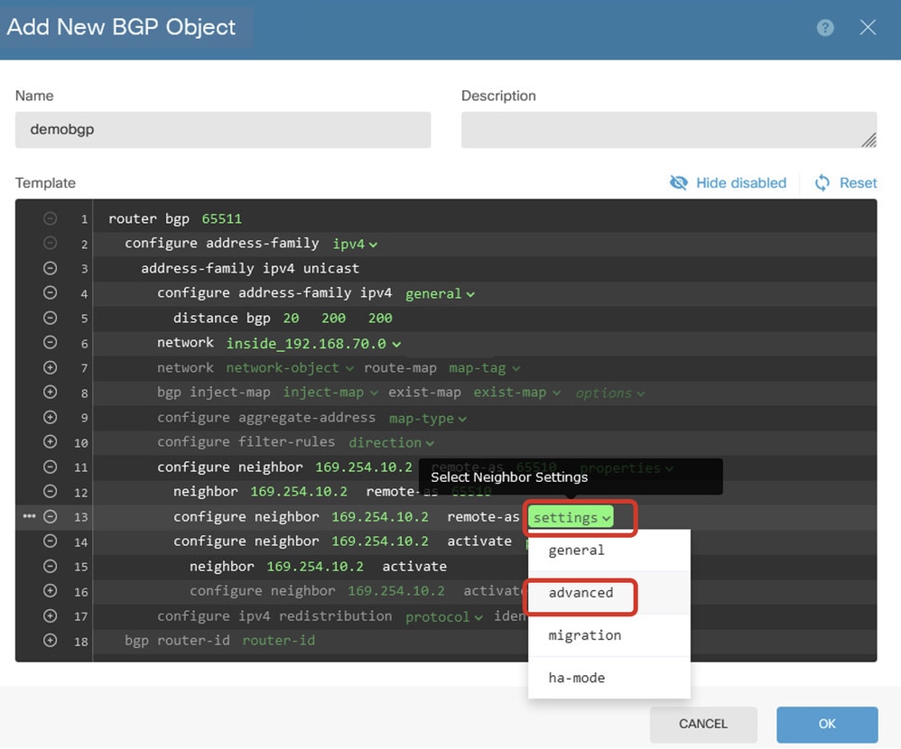 Create_BGP_Object_NeighborSetting_Properties_Advanced
Line 18: Click options and choose disable in order to disable path MTU discovery.
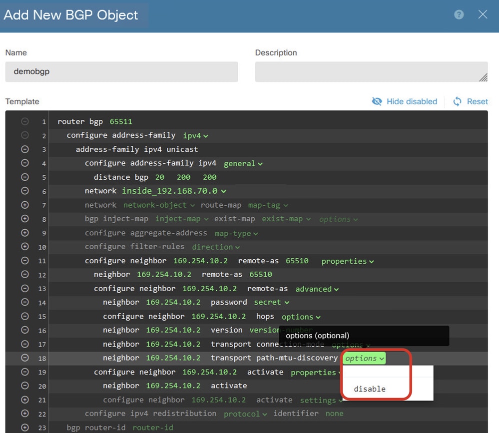 Create_BGP_Object_NeighborSetting_Properties_Advanced_PMD
Line 14, 15, 16, 17: Click the - button in order to disable the lines. Then, click the OK button to save the BGP object.
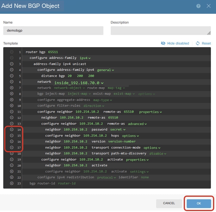 Create_BGP_Object_DisableLines
This is an overview of the BGP setting in this example. You can configure the other BGP settings based on your actual needs.
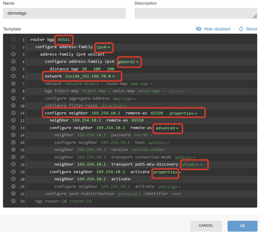 Create_BGP_Object_Final_Overview
Step 7. Deploy the BGP configuration changes.
 Deploy_BGP_Configuration
Step 8. Now the configuration for Site1 FTD is completed.
In order to configure Site2 FTD VPN and BGP, repeat Step 3. to Step 7. with corresponding parameters of Site2 FTD.
Configuration overview of Site1 FTD and Site2 FTD in CLI.
|
Site1 FTD |
Site2 FTD |
|
NGFW Version 7.4.2 interface GigabitEthernet0/0nameif outside cts manual propagate sgt preserve-untag policy static sgt disabled trusted security-level 0 ip address 192.168.30.1 255.255.255.0 interface GigabitEthernet0/2 nameif inside security-level 0 ip address 192.168.70.1 255.255.255.0 interface Tunnel1 nameif demovti ip address 169.254.10.1 255.255.255.0 tunnel source interface outside tunnel destination 192.168.10.1 tunnel mode ipsec ipv4 tunnel protection ipsec profile ipsec_profile|e4084d322d object network OutsideIPv4Gateway host 192.168.30.3 object network inside_192.168.70.0 subnet 192.168.70.0 255.255.255.0 access-group NGFW_ONBOX_ACL global access-list NGFW_ONBOX_ACL remark rule-id 268435457: ACCESS POLICY: NGFW_Access_Policy access-list NGFW_ONBOX_ACL remark rule-id 268435457: L5 RULE: Inside_Outside_Rule access-list NGFW_ONBOX_ACL advanced trust object-group |acSvcg-268435457 ifc inside any ifc outside any rule-id 268435457 event-log both access-list NGFW_ONBOX_ACL remark rule-id 268435458: ACCESS POLICY: NGFW_Access_Policy access-list NGFW_ONBOX_ACL remark rule-id 268435458: L5 RULE: Demo_allow access-list NGFW_ONBOX_ACL advanced permit object-group |acSvcg-268435458 any any rule-id 268435458 event-log both access-list NGFW_ONBOX_ACL remark rule-id 1: ACCESS POLICY: NGFW_Access_Policy access-list NGFW_ONBOX_ACL remark rule-id 1: L5 RULE: DefaultActionRule access-list NGFW_ONBOX_ACL advanced deny ip any any rule-id 1 router bgp 65511 bgp log-neighbor-changes bgp router-id vrf auto-assign address-family ipv4 unicast neighbor 169.254.10.2 remote-as 65510 neighbor 169.254.10.2 transport path-mtu-discovery disable neighbor 169.254.10.2 activate network 192.168.70.0 no auto-summary no synchronization exit-address-family route outside 0.0.0.0 0.0.0.0 192.168.30.3 1 crypto ipsec ikev2 ipsec-proposal AES256_SHA256 protocol esp encryption aes-256 aes protocol esp integrity sha-256 sha-1 crypto ipsec profile ipsec_profile|e4084d322d set ikev2 ipsec-proposal AES256_SHA256 set security-association lifetime kilobytes 4608000 set security-association lifetime seconds 28800 crypto ipsec security-association pmtu-aging infinite crypto ikev2 policy 1 encryption aes-256 aes integrity sha256 sha group 14 prf sha256 sha lifetime seconds 86400 crypto ikev2 policy 20 encryption aes-256 aes-192 aes integrity sha512 sha384 sha256 sha group 21 20 16 15 14 prf sha512 sha384 sha256 sha lifetime seconds 86400 crypto ikev2 enable outside group-policy |s2sGP|192.168.10.1 internal group-policy |s2sGP|192.168.10.1 attributes vpn-tunnel-protocol ikev2 tunnel-group 192.168.10.1 type ipsec-l2l tunnel-group 192.168.10.1 general-attributes default-group-policy |s2sGP|192.168.10.1 tunnel-group 192.168.10.1 ipsec-attributes ikev2 remote-authentication pre-shared-key ***** ikev2 local-authentication pre-shared-key ***** |
NGFW Version 7.4.2 interface GigabitEthernet0/0 nameif outside cts manual propagate sgt preserve-untag policy static sgt disabled trusted security-level 0 ip address 192.168.10.1 255.255.255.0 interface GigabitEthernet0/2 nameif inside security-level 0 ip address 192.168.50.1 255.255.255.0 interface Tunnel1 nameif demovti25 ip address 169.254.10.2 255.255.255.0 tunnel source interface outside tunnel destination 192.168.30.1 tunnel mode ipsec ipv4 tunnel protection ipsec profile ipsec_profile|e4084d322d object network OutsideIPv4Gateway host 192.168.10.3 object network inside_192.168.50.0 subnet 192.168.50.0 255.255.255.0 access-group NGFW_ONBOX_ACL global access-list NGFW_ONBOX_ACL remark rule-id 268435457: ACCESS POLICY: NGFW_Access_Policy access-list NGFW_ONBOX_ACL remark rule-id 268435457: L5 RULE: Inside_Outside_Rule access-list NGFW_ONBOX_ACL advanced trust object-group |acSvcg-268435457 ifc inside any ifc outside any rule-id 268435457 event-log both access-list NGFW_ONBOX_ACL remark rule-id 268435458: ACCESS POLICY: NGFW_Access_Policy access-list NGFW_ONBOX_ACL remark rule-id 268435458: L5 RULE: Demo_allow access-list NGFW_ONBOX_ACL advanced permit object-group |acSvcg-268435458 any any rule-id 268435458 event-log both access-list NGFW_ONBOX_ACL remark rule-id 1: ACCESS POLICY: NGFW_Access_Policy access-list NGFW_ONBOX_ACL remark rule-id 1: L5 RULE: DefaultActionRule access-list NGFW_ONBOX_ACL advanced deny ip any any rule-id 1 router bgp 65510 bgp log-neighbor-changes bgp router-id vrf auto-assign address-family ipv4 unicast neighbor 169.254.10.1 remote-as 65511 neighbor 169.254.10.1 transport path-mtu-discovery disable neighbor 169.254.10.1 activate network 192.168.50.0 no auto-summary no synchronization exit-address-family route outside 0.0.0.0 0.0.0.0 192.168.10.3 1 crypto ipsec ikev2 ipsec-proposal AES256_SHA256 protocol esp encryption aes-256 aes protocol esp integrity sha-256 sha-1 crypto ipsec profile ipsec_profile|e4084d322d set ikev2 ipsec-proposal AES256_SHA256 set security-association lifetime kilobytes 4608000 set security-association lifetime seconds 28800 crypto ipsec security-association pmtu-aging infinite crypto ikev2 policy 1 encryption aes-256 aes integrity sha256 sha group 14 prf sha256 sha lifetime seconds 86400 crypto ikev2 policy 20 encryption aes-256 aes-192 aes integrity sha512 sha384 sha256 sha group 21 20 16 15 14 prf sha512 sha384 sha256 sha lifetime seconds 86400 crypto ikev2 enable outside group-policy |s2sGP|192.168.30.1 internal group-policy |s2sGP|192.168.30.1 attributes vpn-tunnel-protocol ikev2 tunnel-group 192.168.30.1 type ipsec-l2l tunnel-group 192.168.30.1 general-attributes default-group-policy |s2sGP|192.168.30.1 tunnel-group 192.168.30.1 ipsec-attributes ikev2 remote-authentication pre-shared-key ***** ikev2 local-authentication pre-shared-key ***** |
Verify
Use this section in order to confirm that your configuration works properly.
Step 1. Navigate to the CLI of each FTD via console or SSH in order to verify the VPN status of phase 1 and phase 2 through the commands show crypto ikev2 sa and show crypto ipsec sa.
| Site1 FTD | Site2 FTD |
|
ftdv742# show crypto ikev2 sa IKEv2 SAs: Session-id:134, Status:UP-ACTIVE, IKE count:1, CHILD count:1 Tunnel-id Local Remote fvrf/ivrf Status Role 563984431 192.168.30.1/500 192.168.10.1/500 Global/Global READY RESPONDER Encr: AES-CBC, keysize: 256, Hash: SHA256, DH Grp:14, Auth sign: PSK, Auth verify: PSK Life/Active Time: 86400/5145 sec Child sa: local selector 0.0.0.0/0 - 255.255.255.255/65535 remote selector 0.0.0.0/0 - 255.255.255.255/65535 ESP spi in/out: 0xf0c4239d/0xb7b5b38b |
ftdv742# show crypto ikev2 sa
IKEv2 SAs: Session-id:13, Status:UP-ACTIVE, IKE count:1, CHILD count:1 Tunnel-id Local Remote fvrf/ivrf Status Role |
|
ftdv742# show crypto ipsec sa interface: demovti Protected vrf (ivrf): Global #pkts encaps: 5720, #pkts encrypt: 5720, #pkts digest: 5720 local crypto endpt.: 192.168.30.1/500, remote crypto endpt.: 192.168.10.1/500 inbound esp sas: |
ftdv742# show crypto ipsec sa interface: demovti25 Protected vrf (ivrf): Global #pkts encaps: 5721, #pkts encrypt: 5721, #pkts digest: 5721 local crypto endpt.: 192.168.10.1/500, remote crypto endpt.: 192.168.30.1/500 inbound esp sas: |
Step 2. Navigate to the CLI of each FTD via console or SSH in order to verify the BGP status using the commands show bgp neighbors and show route bgp.
| Site1 FTD | Site2 FTD |
|
ftdv742# show bgp neighbors BGP neighbor is 169.254.10.2, vrf single_vf, remote AS 65510, external link Outbound Inbound Address tracking is enabled, the RIB does have a route to 169.254.10.2 |
ftdv742# show bgp neighbors BGP neighbor is 169.254.10.1, vrf single_vf, remote AS 65511, external link Outbound Inbound Address tracking is enabled, the RIB does have a route to 169.254.10.1 |
|
ftdv742# show route bgp Codes: L - local, C - connected, S - static, R - RIP, M - mobile, B - BGP B 192.168.50.0 255.255.255.0 [20/0] via 169.254.10.2, 1d20h |
ftdv742# show route bgp Codes: L - local, C - connected, S - static, R - RIP, M - mobile, B - BGP B 192.168.70.0 255.255.255.0 [20/0] via 169.254.10.1, 1d20h |
Step 3. Site1 Client and Site2 Client ping each other successfully.
Site1 Client:
Site1_Client#ping 192.168.50.2
Type escape sequence to abort.
Sending 5, 100-byte ICMP Echos to 192.168.50.2, timeout is 2 seconds:
!!!!!
Success rate is 100 percent (5/5), round-trip min/avg/max = 31/56/90 ms
Site2 Client:
Site2_Client#ping 192.168.70.2
Type escape sequence to abort.
Sending 5, 100-byte ICMP Echos to 192.168.70.2, timeout is 2 seconds:
!!!!!
Success rate is 100 percent (5/5), round-trip min/avg/max = 12/39/71 ms
Troubleshoot
This section provides information you can use in order to troubleshoot your configuration.
You can use those debug commands in order to troubleshoot the VPN section.
debug crypto ikev2 platform 255
debug crypto ikev2 protocol 255
debug crypto ipsec 255
debug vti 255
You can use those debug commands in order to troubleshoot the BGP section.
ftdv742# debug ip bgp ?

A.B.C.D    BGP neighbor address
all All    address families
events     BGP events
import     BGP path import across topologies, VRFs or AFs in BGP Inbound information
ipv4       Address family
ipv6       Address family
keepalives BGP keepalives
out        BGP Outbound information
range      BGP dynamic range
rib-filter Next hop route watch filter events
updates    BGP updates
vpnv4      Address family
vpnv6      Address family
vrf        VRF scope
<cr>
Revision History
| Revision | Publish Date | Comments |
|---|---|---|
1.0 |
21-Oct-2024 |
Initial Release |
Contributed by Cisco Engineers
- Mark NiCisco Technical Leader
- Chao FengCisco Technical Leader
Contact Cisco
- Open a Support Case

- (Requires a Cisco Service Contract)
 Feedback