Configure VRF Aware Route-Based Site-to-Site VPN on FTD Managed by FDM
Available Languages
Download Options
Bias-Free Language
The documentation set for this product strives to use bias-free language. For the purposes of this documentation set, bias-free is defined as language that does not imply discrimination based on age, disability, gender, racial identity, ethnic identity, sexual orientation, socioeconomic status, and intersectionality. Exceptions may be present in the documentation due to language that is hardcoded in the user interfaces of the product software, language used based on RFP documentation, or language that is used by a referenced third-party product. Learn more about how Cisco is using Inclusive Language.
Introduction
This document describes how to configure VRF aware route-based site-to-site VPN on FTD managed by FDM.
Prerequisites
Requirements
Cisco recommends that you have knowledge of these topics:
- Basic understanding of VPN
- Basic understanding of Virtual Routing and Forwarding (VRF)
- Experience with FDM
Components Used
The information in this document is based on these software and hardware versions:
- Cisco FTDv version 7.4.2
- Cisco FDM version 7.4.2
- Cisco ASAv version 9.20.3
The information in this document was created from the devices in a specific lab environment. All of the devices used in this document started with a cleared (default) configuration. If your network is live, ensure that you understand the potential impact of any command.
Background Information
Virtual Routing and Forwarding (VRF) on Firepower Device Manager (FDM) allows you to create multiple isolated routing instances on a single Firepower Threat Defense (FTD) device. Each VRF instance operates as a separate virtual router with its own routing table, enabling logical separation of network traffic and providing enhanced security and traffic management capabilities.
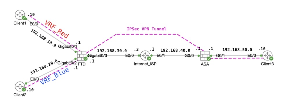
This document explains how to configure VRF aware IPSec VPN with VTI. VRF Red network and VRF Blue network are behind FTD. Client1 in VRF Red network and Client2 in VRF Blue would communicate with Client 3 behind ASA through the IPSec VPN tunnel.
Configure
Network Diagram
 Topology
Configure the FTD
Step 1. It is essential to ensure that the preliminary configuration of IP interconnectivity between nodes has been duly completed. The Client1 and Client2 are with FTD Inside IP address as gateway. The Client3 is with ASA inside IP address as gateway.
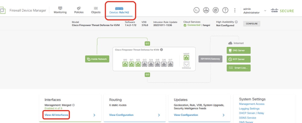
Step 2. Create virtual tunnel interface. Login the FDM GUI of FTD. Navigate to Device > Interfaces . Click View All Interfaces .
 FTD_View_Interfaces
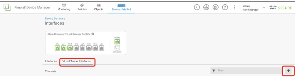
Step 2.1. Click Virtual Tunnel Interfaces tab. Click + button.
 FTD_Create_VTI
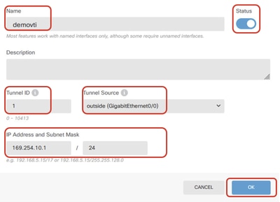
Step 2.2. Provide necessary information. Click OK button.
- Name: demovti
- Tunnel ID: 1
- Tunnel Source: outside (GigabitEthernet0/0)
- IP Address And Subnet Mask: 169.254.10.1/24
- Status: click the slider to the Enabled position
 FTD_Create_VTI_Details
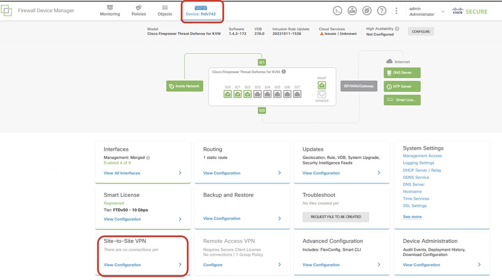
Step 3. Navigate to Device > Site-to-Site VPN . Click View Configuration button.
 FTD_Site-to-Site_VPN_View_Configurations
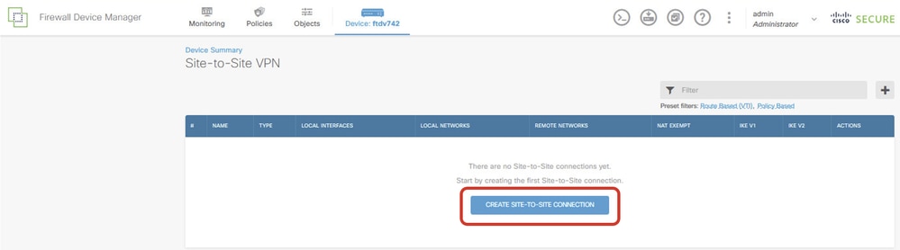
Step 3.1. Start to create new site-to-site VPN. Click CREATE SITE-TO-SITE CONNECTION button. Or click + button.
 FTD_Create_Site2Site_Connection
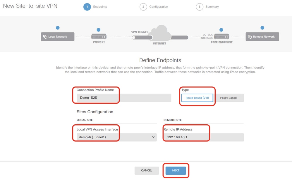
Step 3.2. Provide necessary information. Click NEXT button.
- Connection Profile Name: Demo_S2S
- Type: Route Based (VTI)
- Local VPN Access Interface: demovti (created in Step 2)
- Remote IP Address: 192.168.40.1 (this is peer ASA outside IP address)
 FTD_Site-to-Site_VPN_Endpoints
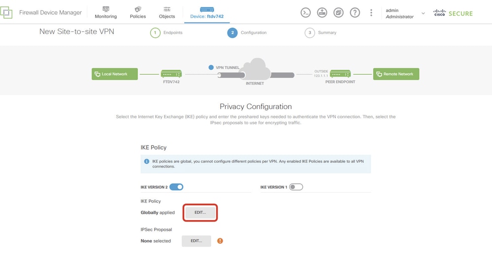
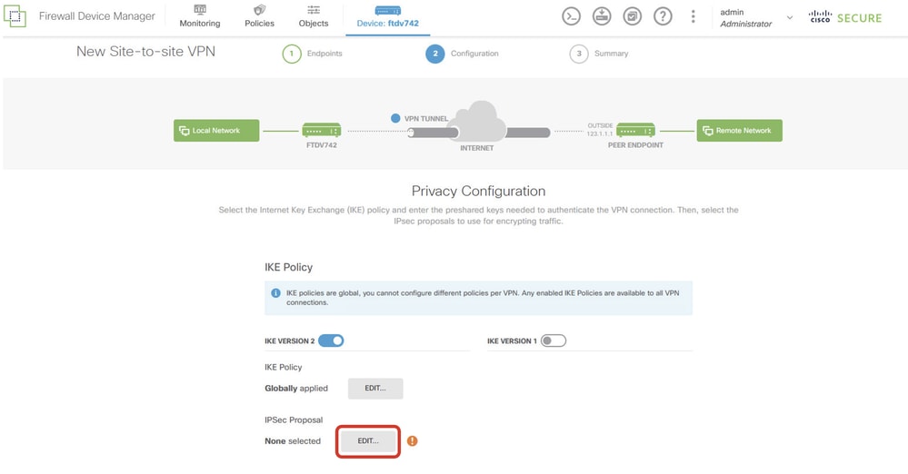
Step 3.3. Navigate to IKE Policy. Click EDIT button.
 FTD_Edit_IKE_Policy
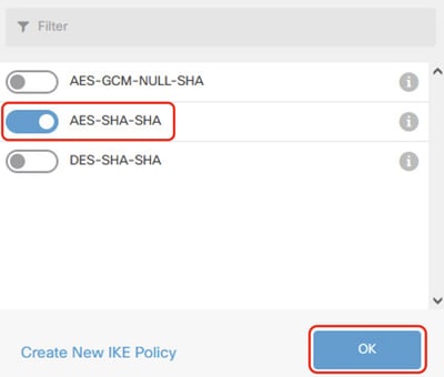
Step 3.4. For IKE policy, you can use pre-defined or you can create a new one by clicking Create New IKE Policy .
In this example, toggle an existing IKE policy name AES-SHA-SHA . Click OK button to save.
 FTD_Enable_IKE_Policy
Step 3.5. Navigate to IPSec Proposal. Click EDIT button.
 FTD_Edit_IPSec_Proposal
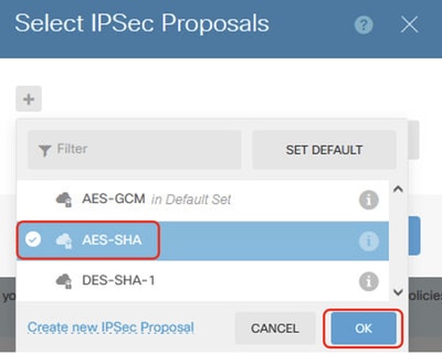
Step 3.6. For IPSec proposal, you can use pre-defined or you can create a new one by clicking Create new IPSec Proposal .
In this example, toggle an existing IPSec Proposal name AES-SHA . Click OK button to save.
 FTD_Enable_IPSec_Proposal
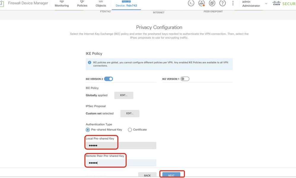
Step 3.7. Scroll down the page and configure the pre-shared key. Click NEXT button.
Please note down this pre-shared key and configure it on ASA later.
 FTD_Configure_Pre_Shared_Key
Step 3.8. Review the VPN configuration. If anything needs to be modified, click BACK button. If everything is good, click FINISH button.
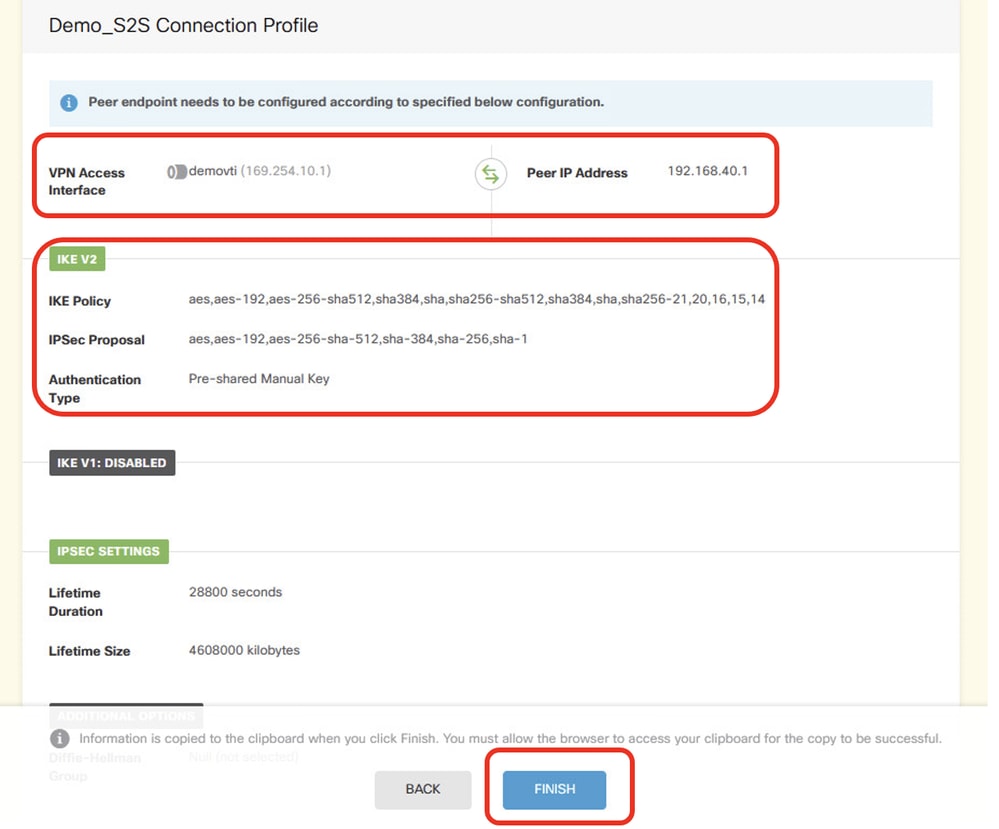 FTD_Review_VPN_Configuration
Step 3.9. Create Access Control rule to allow traffic pass through the FTD. In this example, allow all for demo purpose. Please modify your policy based on your actual needs.
 FTD_ACP_Example
Step 3.10. (Optional) Configure NAT exempt rule for the client traffic on FTD if there is dynamic NAT configured for client to access internet. In this example, there is no need to configure a NAT exempt rule because there is no dynamic NAT configured on FTD.
Step 3.11. Deploy the configuration changes.
 FTD_Deployment_Changes
Step 4. Configure virtual routers.
Step 4.1. Create network objects for static route. Navigate to Objects > Networks , click + button.
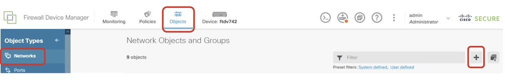 FTD_Create_NetObjects
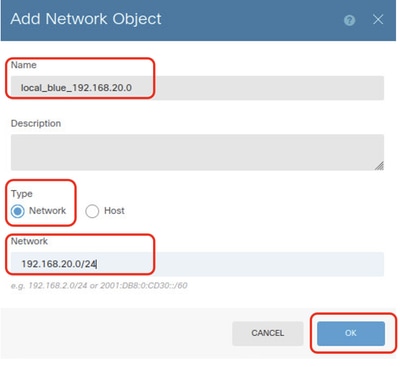
Step 4.2. Provide necessary information of each network object. Click OK button.
- Name: local_blue_192.168.20.0
- Type: Network
- Network: 192.168.20.0/24
 FTD_VRF_Blue_Network
- Name: local_red_192.168.10.0
- Type: Network
- Network: 192.168.10.0/24
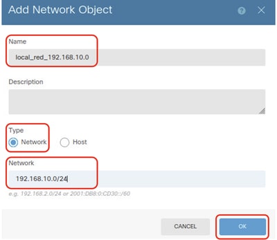 FTD_VRF_Red_Network
- Name: remote_192.168.50.0
- Type: Network
- Network: 192.168.50.0/24
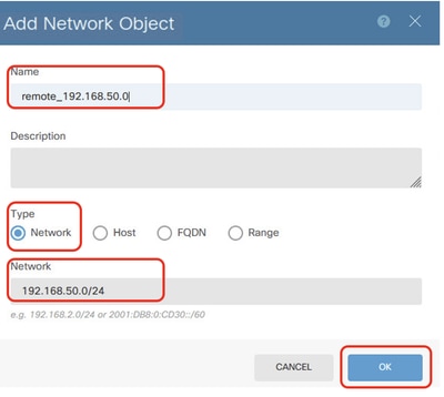 FTD_Remote_Network
Step 4.3. Create first virtual router. Navigate to Device > Routing . Click View Configuration .
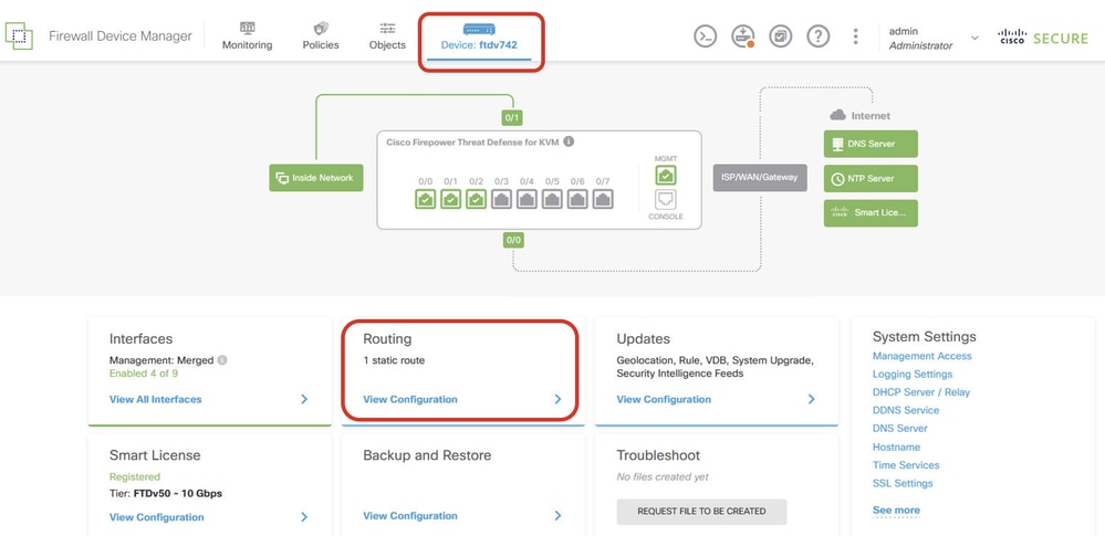 FTD_View_Routing_Configuration
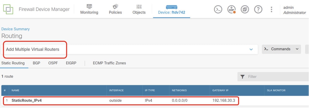
Step 4.4. Click Add Multiple Virtual Routers .
Note: a static route through outside interface has already been configured during FDM initialization. If you do not have it, please configure it manually.
 FTD_Add_First_Virtual_Router1
Step 4.5. Click CREATE FIRST CUSTOM VIRTUAL ROUTER .
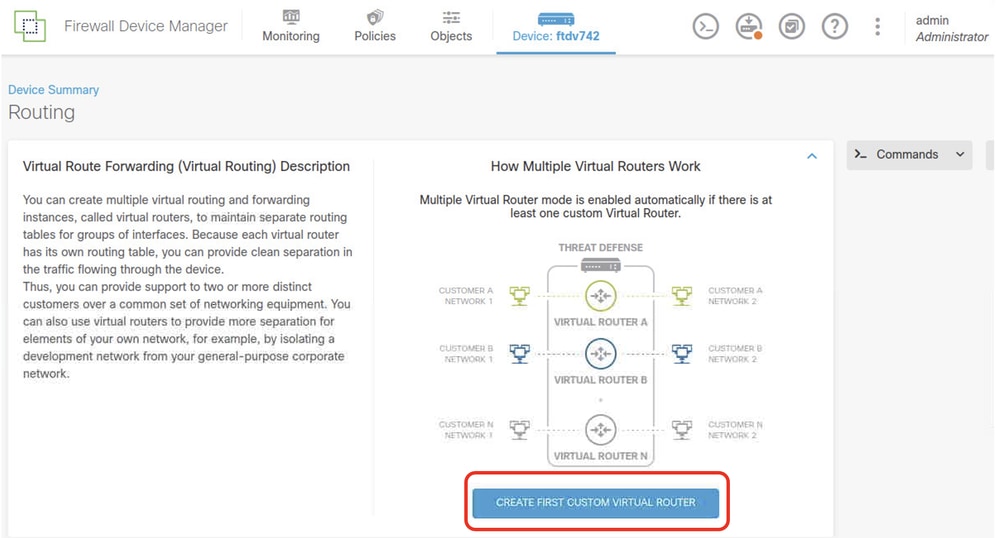 FTD_Add_First_Virtual_Router2
Step 4.6. Provide necessary information of first virtual router. Click OK button. After first virtual router creation, a vrf name Global would be shown automatically.
- Name: vrf_red
- Interfaces: inside_red (GigabitEthernet0/1)
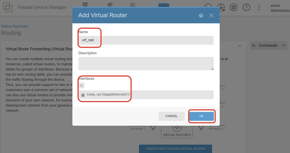 FTD_Add_First_Virtual_Router3
Step 4.7. Create second virtual router. Navigate to Device > Routing . Click View Configuration . Click + button.
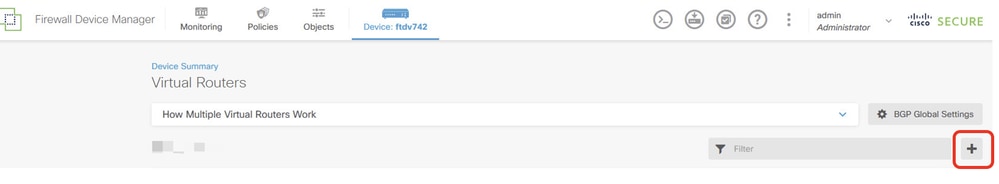 FTD_Add_Second_Virtual_Router
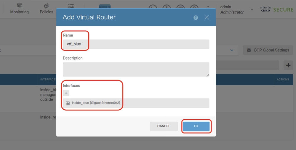
Step 4.8. Provide necessary information of second virtual router. Click OK button
- Name: vrf_blue
- Interfaces: inside_blue (GigabitEthernet0/2)
 FTD_Add_Second_Virtual_Router2
Step 5. Create route leak from vrf_blue to Global. This route allows endpoints on the 192.168.20.0/24 network to initiate connections that would traverse the site-to-site VPN tunnel. For this example, the remote endpoint is protecting the 192.168.50.0/24 network.
Navigate to Device > Routing . Click View Configuration . click the View icon in the Action cell for the virtual router vrf_blue.
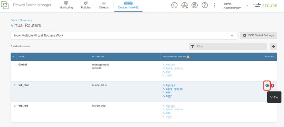 FTD_View_VRF_Blue
Step 5.1. Click Static Routing tab. Click + button.
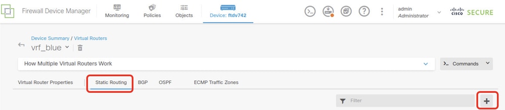 FTD_Create_Static_Route_VRF_Blue
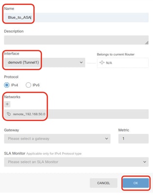
Step 5.2. Provide necessary information. Click OK button.
- Name: Blue_to_ASA
- Interface: demovti (Tunnel1)
- Networks: remote_192.168.50.0
- Gateway: Leave this item blank.
 FTD_Create_Static_Route_VRF_Blue_Details
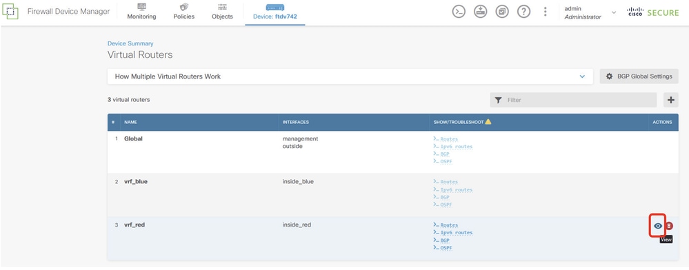
Step 6. Create route leak from vrf_red to Global. This route allows endpoints on the 192.168.10.0/24 network to initiate connections that would traverse the site-to-site VPN tunnel. For this example, the remote endpoint is protecting the 192.168.50.0/24 network.
Navigate to Device > Routing . Click View Configuration . click the View icon in the Action cell for the virtual router vrf_red.
 FTD_View_VRF_Red
Step 6.1. Click Static Routing tab. Click + button.
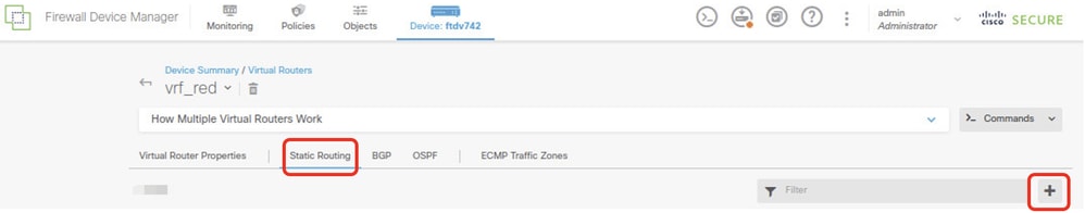 FTD_Create_Static_Route_VRF_Red
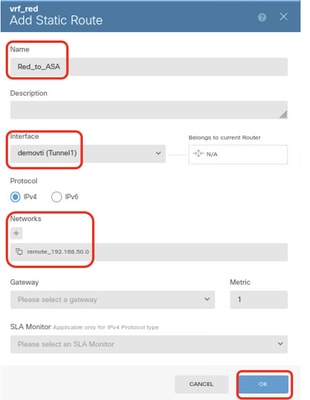
Step 6.2. Provide necessary information. Click OK button.
- Name: Red_to_ASA
- Interface: demovti (Tunnel1)
- Networks: remote_192.168.50.0
- Gateway: Leave this item blank.
 FTD_Create_Static_Route_VRF_Red_Details
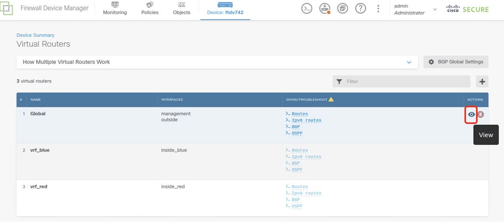
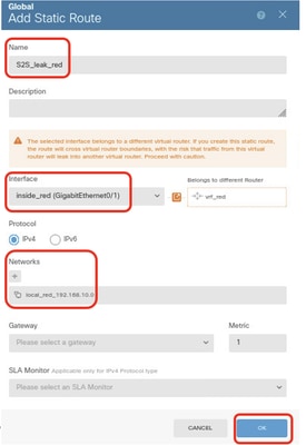
Step 7. Create route leak from Global to virtual routers. The routes allows endpoints protected by the remote end of the site-to-site VPN to access the 192.168.10.0/24 network in the vrf_red virtual router and 192.168.20.0/24 network in the vrf_blue virtual router.
Navigate to Device > Routing . Click View Configuration . click the View icon in the Action cell for the Global virtual router.
 FTD_View_VRF_Global
Step 7.1. Click Static Routing tab. Click + button.
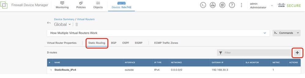 FTD_Create_Static_Route_VRF_Global
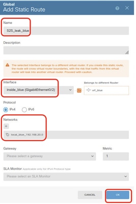
Step 7.2. Provide necessary information. Click OK button.
- Name: S2S_leak_blue
- Interface: inside_blue (GigabitEthernet0/2)
- Networks: local_blue_192.168.20.0
- Gateway: Leave this item blank.
 FTD_Create_Static_Route_VRF_Global_To_Blue
- Name: S2S_leak_red
- Interface: inside_red (GigabitEthernet0/1)
- Networks: local_red_192.168.10.0
- Gateway: Leave this item blank.
 FTD_Create_Static_Route_VRF_Global_To_Red
Step 8. Deploy the configuration changes.
 FTD_Deployment_Changes
Configure the ASA
Step 9. Create the IKEv2 policy that defines the same parameters configured on the FTD.
crypto ikev2 policy 20
 encryption aes-256 aes-192 aes
 integrity sha512 sha384 sha256 sha
 group 21 20 16 15 14
 prf sha512 sha384 sha256 sha
 lifetime seconds 86400
Step 10. Create an IKEv2 ipsec-proposal that defines the same parameters configured on the FTD.
crypto ipsec ikev2 ipsec-proposal AES-SHA
 protocol esp encryption aes-256 aes-192 aes
 protocol esp integrity sha-512 sha-384 sha-256 sha-1
Step 11. Create an ipsec profile, referencing ipsec-proposal created in Step 10.
crypto ipsec profile demo_ipsec_profile
 set ikev2 ipsec-proposal AES-SHA
 set security-association lifetime kilobytes 4608000
 set security-association lifetime seconds 28800
Step 12. Create a group-policy allowing the IKEv2 protocol.
group-policy demo_gp_192.168.30.1 internal
group-policy demo_gp_192.168.30.1 attributes
 vpn-tunnel-protocol ikev2
Step 13. Create a tunnel group for the peer FTD outside IP address, referencing the group-policy created in Step 12 and configuring the same pre-shared-key with FTD(created in Step 3.7).
tunnel-group 192.168.30.1 type ipsec-l2l
tunnel-group 192.168.30.1 general-attributes
 default-group-policy demo_gp_192.168.30.1

tunnel-group 192.168.30.1 ipsec-attributes
 ikev2 remote-authentication pre-shared-key *****
 ikev2 local-authentication pre-shared-key *****
Step 14. Enable IKEv2 on the outside interface.
crypto ikev2 enable outsideStep 15. Create virtual tunnel.
interface Tunnel1
 nameif demovti_asa
 ip address 169.254.10.2 255.255.255.0
 tunnel source interface outside
 tunnel destination 192.168.30.1
 tunnel mode ipsec ipv4
 tunnel protection ipsec profile demo_ipsec_profile
Step 16. Create static route.
route demovti_asa 192.168.10.0 255.255.255.0 169.254.10.1 1
route demovti_asa 192.168.20.0 255.255.255.0 169.254.10.1 1
route outside 0.0.0.0 0.0.0.0 192.168.40.3 1
Verify
Use this section in order to confirm that your configuration works properly.
Step 1. Navigate to the CLI of FTD and ASA via console or SSH to verify the VPN status of phase 1 and phase 2 through commands show crypto ikev2 sa and show crypto ipsec sa .
FTD:
> system support diagnostic-cli
Attaching to Diagnostic CLI ... Press 'Ctrl+a then d' to detach.
Type help or '?' for a list of available commands.

ftdv742#
ftdv742# show crypto ikev2 sa

IKEv2 SAs:

Session-id:4, Status:UP-ACTIVE, IKE count:1, CHILD count:1

Tunnel-id Local                                               Remote                                     fvrf/ivrf     Status         Role
 32157565 192.168.30.1/500                                    192.168.40.1/500                        Global/Global      READY    RESPONDER
      Encr: AES-CBC, keysize: 256, Hash: SHA512, DH Grp:21, Auth sign: PSK, Auth verify: PSK
      Life/Active Time: 86400/67986 sec
Child sa: local selector  0.0.0.0/0 - 255.255.255.255/65535
          remote selector 0.0.0.0/0 - 255.255.255.255/65535
          ESP spi in/out: 0x4cf55637/0xa493cc83

ftdv742# show crypto ipsec sa
interface: demovti
    Crypto map tag: __vti-crypto-map-Tunnel1-0-1, seq num: 65280, local addr: 192.168.30.1

      Protected vrf (ivrf): Global
      local ident (addr/mask/prot/port): (0.0.0.0/0.0.0.0/0/0)
      remote ident (addr/mask/prot/port): (0.0.0.0/0.0.0.0/0/0)
      current_peer: 192.168.40.1


      #pkts encaps: 30, #pkts encrypt: 30, #pkts digest: 30
      #pkts decaps: 30, #pkts decrypt: 30, #pkts verify: 30
      #pkts compressed: 0, #pkts decompressed: 0
      #pkts not compressed: 30, #pkts comp failed: 0, #pkts decomp failed: 0
      #pre-frag successes: 0, #pre-frag failures: 0, #fragments created: 0
      #PMTUs sent: 0, #PMTUs rcvd: 0, #decapsulated frgs needing reassembly: 0
      #TFC rcvd: 0, #TFC sent: 0
      #Valid ICMP Errors rcvd: 0, #Invalid ICMP Errors rcvd: 0
      #send errors: 0, #recv errors: 0

      local crypto endpt.: 192.168.30.1/500, remote crypto endpt.: 192.168.40.1/500
      path mtu 1500, ipsec overhead 94(44), media mtu 1500
      PMTU time remaining (sec): 0, DF policy: copy-df
      ICMP error validation: disabled, TFC packets: disabled
      current outbound spi: A493CC83
      current inbound spi : 4CF55637

    inbound esp sas:
      spi: 0x4CF55637 (1291146807)
         SA State: active
         transform: esp-aes-256 esp-sha-512-hmac no compression
         in use settings ={L2L, Tunnel, IKEv2, VTI, }
         slot: 0, conn_id: 13, crypto-map: __vti-crypto-map-Tunnel1-0-1
         sa timing: remaining key lifetime (kB/sec): (4055040/16867)
         IV size: 16 bytes
         replay detection support: Y
         Anti replay bitmap:
          0x00000000 0x00000001
    outbound esp sas:
      spi: 0xA493CC83 (2761149571)
         SA State: active
         transform: esp-aes-256 esp-sha-512-hmac no compression
         in use settings ={L2L, Tunnel, IKEv2, VTI, }
         slot: 0, conn_id: 13, crypto-map: __vti-crypto-map-Tunnel1-0-1
         sa timing: remaining key lifetime (kB/sec): (4285440/16867)
         IV size: 16 bytes
         replay detection support: Y
         Anti replay bitmap:
          0x00000000 0x00000001
ASA:
ASA9203# show crypto ikev2 sa

IKEv2 SAs:

Session-id:4, Status:UP-ACTIVE, IKE count:1, CHILD count:1

Tunnel-id Local                                               Remote                                     fvrf/ivrf     Status         Role
 26025779 192.168.40.1/500                                    192.168.30.1/500                        Global/Global      READY    INITIATOR
      Encr: AES-CBC, keysize: 256, Hash: SHA512, DH Grp:21, Auth sign: PSK, Auth verify: PSK
      Life/Active Time: 86400/68112 sec
Child sa: local selector  0.0.0.0/0 - 255.255.255.255/65535
          remote selector 0.0.0.0/0 - 255.255.255.255/65535
          ESP spi in/out: 0xa493cc83/0x4cf55637
ASA9203#
ASA9203# show cry
ASA9203# show crypto ipsec sa
interface: demovti_asa
    Crypto map tag: __vti-crypto-map-Tunnel1-0-1, seq num: 65280, local addr: 192.168.40.1

      Protected vrf (ivrf): Global
      local ident (addr/mask/prot/port): (0.0.0.0/0.0.0.0/0/0)
      remote ident (addr/mask/prot/port): (0.0.0.0/0.0.0.0/0/0)
      current_peer: 192.168.30.1


      #pkts encaps: 30, #pkts encrypt: 30, #pkts digest: 30
      #pkts decaps: 30, #pkts decrypt: 30, #pkts verify: 30
      #pkts compressed: 0, #pkts decompressed: 0
      #pkts not compressed: 30, #pkts comp failed: 0, #pkts decomp failed: 0
      #pre-frag successes: 0, #pre-frag failures: 0, #fragments created: 0
      #PMTUs sent: 0, #PMTUs rcvd: 0, #decapsulated frgs needing reassembly: 0
      #TFC rcvd: 0, #TFC sent: 0
      #Valid ICMP Errors rcvd: 0, #Invalid ICMP Errors rcvd: 0
      #send errors: 0, #recv errors: 0

      local crypto endpt.: 192.168.40.1/500, remote crypto endpt.: 192.168.30.1/500
      path mtu 1500, ipsec overhead 94(44), media mtu 1500
      PMTU time remaining (sec): 0, DF policy: copy-df
      ICMP error validation: disabled, TFC packets: disabled
      current outbound spi: 4CF55637
      current inbound spi : A493CC83

    inbound esp sas:
      spi: 0xA493CC83 (2761149571)
         SA State: active
         transform: esp-aes-256 esp-sha-512-hmac no compression
         in use settings ={L2L, Tunnel, IKEv2, VTI, }
         slot: 0, conn_id: 4, crypto-map: __vti-crypto-map-Tunnel1-0-1
         sa timing: remaining key lifetime (kB/sec): (4101120/16804)
         IV size: 16 bytes
         replay detection support: Y
         Anti replay bitmap:
          0x00000000 0x00000001
    outbound esp sas:
      spi: 0x4CF55637 (1291146807)
         SA State: active
         transform: esp-aes-256 esp-sha-512-hmac no compression
         in use settings ={L2L, Tunnel, IKEv2, VTI, }
         slot: 0, conn_id: 4, crypto-map: __vti-crypto-map-Tunnel1-0-1
         sa timing: remaining key lifetime (kB/sec): (4055040/16804)
         IV size: 16 bytes
         replay detection support: Y
         Anti replay bitmap:
          0x00000000 0x00000001
Step 2. Verify the route of VRF and Global on FTD.
ftdv742# show route

Codes: L - local, C - connected, S - static, R - RIP, M - mobile, B - BGP
       D - EIGRP, EX - EIGRP external, O - OSPF, IA - OSPF inter area
       N1 - OSPF NSSA external type 1, N2 - OSPF NSSA external type 2
       E1 - OSPF external type 1, E2 - OSPF external type 2, V - VPN
       i - IS-IS, su - IS-IS summary, L1 - IS-IS level-1, L2 - IS-IS level-2
       ia - IS-IS inter area, * - candidate default, U - per-user static route
       o - ODR, P - periodic downloaded static route, + - replicated route
       SI - Static InterVRF, BI - BGP InterVRF
Gateway of last resort is 192.168.30.3 to network 0.0.0.0

S*       0.0.0.0 0.0.0.0 [1/0] via 192.168.30.3, outside
C        169.254.10.0 255.255.255.0 is directly connected, demovti
L        169.254.10.1 255.255.255.255 is directly connected, demovti
SI       192.168.10.0 255.255.255.0 [1/0] is directly connected, inside_red
SI       192.168.20.0 255.255.255.0 [1/0] is directly connected, inside_blue
C        192.168.30.0 255.255.255.0 is directly connected, outside
L        192.168.30.1 255.255.255.255 is directly connected, outside


ftdv742# show route vrf vrf_blue


Routing Table: vrf_blue
Codes: L - local, C - connected, S - static, R - RIP, M - mobile, B - BGP
       D - EIGRP, EX - EIGRP external, O - OSPF, IA - OSPF inter area
       N1 - OSPF NSSA external type 1, N2 - OSPF NSSA external type 2
       E1 - OSPF external type 1, E2 - OSPF external type 2, V - VPN
       i - IS-IS, su - IS-IS summary, L1 - IS-IS level-1, L2 - IS-IS level-2
       ia - IS-IS inter area, * - candidate default, U - per-user static route
       o - ODR, P - periodic downloaded static route, + - replicated route
       SI - Static InterVRF, BI - BGP InterVRF
Gateway of last resort is not set

C        192.168.20.0 255.255.255.0 is directly connected, inside_blue
L        192.168.20.1 255.255.255.255 is directly connected, inside_blue
SI       192.168.50.0 255.255.255.0 [1/0] is directly connected, demovti


ftdv742# show route vrf vrf_red


Routing Table: vrf_red
Codes: L - local, C - connected, S - static, R - RIP, M - mobile, B - BGP
       D - EIGRP, EX - EIGRP external, O - OSPF, IA - OSPF inter area
       N1 - OSPF NSSA external type 1, N2 - OSPF NSSA external type 2
       E1 - OSPF external type 1, E2 - OSPF external type 2, V - VPN
       i - IS-IS, su - IS-IS summary, L1 - IS-IS level-1, L2 - IS-IS level-2
       ia - IS-IS inter area, * - candidate default, U - per-user static route
       o - ODR, P - periodic downloaded static route, + - replicated route
       SI - Static InterVRF, BI - BGP InterVRF
Gateway of last resort is not set

C        192.168.10.0 255.255.255.0 is directly connected, inside_red
L        192.168.10.1 255.255.255.255 is directly connected, inside_red
SI       192.168.50.0 255.255.255.0 [1/0] is directly connected, demovti
Step 3. Verify ping test.
Before ping, check the counters of show crypto ipsec sa | inc interface:|encap|decap on FTD.
In this example, Tunnel1 shows 30 packets for both encapsulation and decapsulation.
ftdv742# show crypto ipsec sa | inc interface:|encap|decap
interface: demovti
      #pkts encaps: 30, #pkts encrypt: 30, #pkts digest: 30
      #pkts decaps: 30, #pkts decrypt: 30, #pkts verify: 30
      #PMTUs sent: 0, #PMTUs rcvd: 0, #decapsulated frgs needing reassembly: 0
ftdv742#
Client1 ping Client3 successfully.
Client1#ping 192.168.50.10
Type escape sequence to abort.
Sending 5, 100-byte ICMP Echos to 192.168.50.10, timeout is 2 seconds:
!!!!!
Success rate is 100 percent (5/5), round-trip min/avg/max = 5/299/620 ms
Client2 ping Client3 successfully.
Client2#ping 192.168.50.10
Type escape sequence to abort.
Sending 5, 100-byte ICMP Echos to 192.168.50.10, timeout is 2 seconds:
!!!!!
Success rate is 100 percent (5/5), round-trip min/avg/max = 11/297/576 ms
Check the counters of show crypto ipsec sa | inc interface:|encap|decap on FTD after ping successfully.
In this example, Tunnel1 shows 40 packets for both encapsulation and decapsulation after a successful ping. Additionally, both counters increased by 10 packets, matching the 10 ping echo requests, indicating that the ping traffic successfully passed through the IPSec tunnel.
ftdv742# show crypto ipsec sa | inc interface:|encap|decap
interface: demovti
      #pkts encaps: 40, #pkts encrypt: 40, #pkts digest: 40
      #pkts decaps: 40, #pkts decrypt: 40, #pkts verify: 40
      #PMTUs sent: 0, #PMTUs rcvd: 0, #decapsulated frgs needing reassembly: 0
Troubleshoot
This section provides information you can use in order to troubleshoot your configuration.
You can use those debug commands to troubleshoot the VPN section.
debug crypto ikev2 platform 255
debug crypto ikev2 protocol 255
debug crypto ipsec 255
debug vti 255
You can use those debug commands to troubleshoot the route section.
debug ip routing
Reference
Revision History
| Revision | Publish Date | Comments |
|---|---|---|
1.0 |
19-Dec-2024 |
Initial Release |
Contributed by Cisco Engineers
- Mark NiCisco Technical Leader
 Feedback
Contact Cisco
- Open a Support Case

- (Requires a Cisco Service Contract)