Introduction
This document describes the Inline Sets for FDM added in Cisco Secure Firewall 7.4.1.
Prerequisites
Requirements
Cisco recommends you have knowledge of these topics:
- FDM concepts and configuration
- Applies to FTDs on the 1000, 2100, and 3100 Series platforms managed by FDM
Components Used
The information in this document is based on FDM 7.4.2.
The information in this document was created from the devices in a specific lab environment. All of the devices used in this document started with a cleared (default) configuration. If your network is live, ensure that you understand the potential impact of any command.
Background Information
An inline set provides an IPS-only interface. You can implement IPS-only interfaces if you have a separate firewall protecting these interfaces and do not want the overhead of firewall functions.
An inline set acts like a bump on the wire, binding two interfaces together to slot into an existing network. This function allows the device to be installed in any network environment without the configuration of adjacent network devices. Inline interfaces receive all traffic unconditionally, but all traffic received on these interfaces is retransmitted out of an inline set unless explicitly dropped.
Guidelines and Limitations
-
You cannot change the attributes of the interfaces used in an inline set: name, mode, interface ID, MTU, IP address.
-
Bidirectional Forwarding Detection (BFD) echo packets are not allowed through the device when using inline sets. If there are two neighbors on either side of the device running BFD, then the device drops BFD echo packets because they have the same source and destination IP address and appear to be part of a LAND attack.
-
For inline sets and passive interfaces, the device supports up to two 802.1Q headers in a packet (also known as Q-in-Q support).
Note: Firewall-type interfaces do not support Q-in-Q, and only support one 802.1Q header.
-
Interfaces in an inline set do not support routing, NAT, DHCP (server, client, or relay), VPN, TCP Intercept, application inspection, or Netflow.
-
Configure the physical or EtherChannel interfaces that can be members of the inline set. You can configure these values only: Name, duplex, speed, and Routed mode (do not select passive). Do not configure any type of addressing, that is, manual IP addresses, DHCP, or PPoE.
Inline Mode Details
- This feature allows you to use Inline sets. This enables traffic inspection without IP allocation.
- Inline Mode is available for physical interfaces, EtherChannels, and Security Zones.
- Inline Mode is automatically set for Interfaces and EtherChannels when they are used in an Inline Pair.
- Inline Mode prevents changes from being made on the involved Interfaces and EtherChannels until they are removed from the Inline Pair.
- Interfaces that are in Inline Mode can be associated with Security Zones set to Inline Mode.
Inline Set Network Diagram
Traffic flows from Router1 to Router2 through Interfaces A and B using only a physical connection.
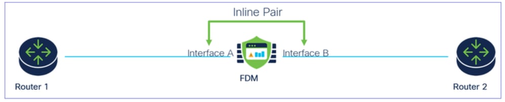 Network Diagram
Configure Inline Set
- From the FDM dashboard, navigate to Interfaces card.
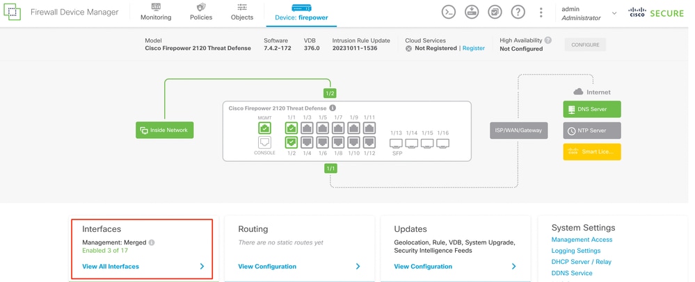 Interfaces Tab
- To enable interfaces, click Status icon of the interface.
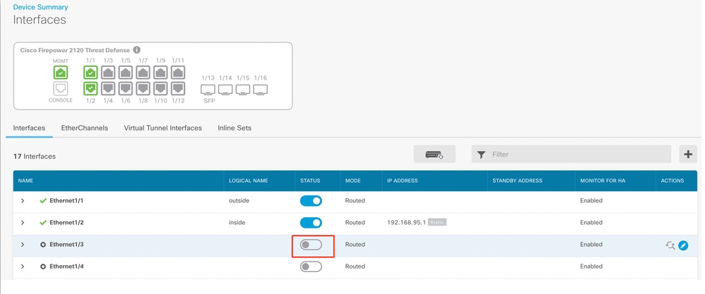 Status Icon
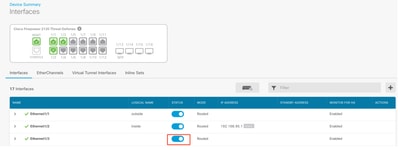 Enable Interface
- To Edit interfaces, click Edit (pencil) icon for the interface.
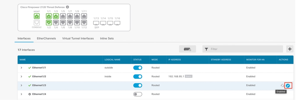 Edit Interface
- Enter the Interface Name and select the mode as Routed. Do not configure any IP Address.
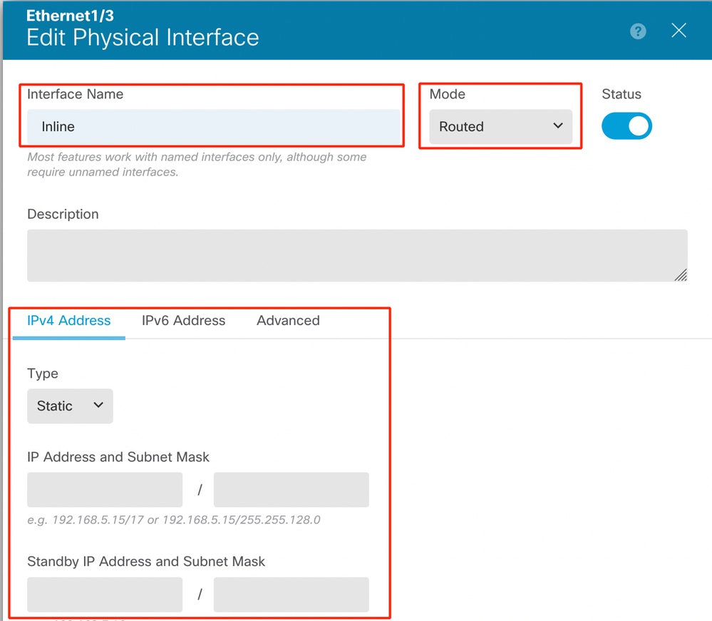 Edit Interface
- To create an Inline Set, navigate to Inline Sets Tab.
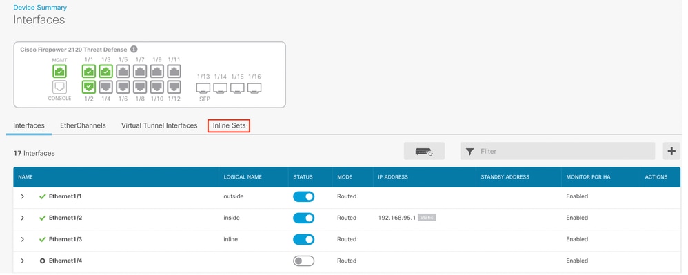 Create Inline Set
To add an Inline Set, click Add (+ icon).
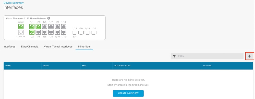 Add Inline Set
- Set a name for the inline set.
- Set desired MTU (optional)�. The default is 1500, which is the minimum supported MTU.
- In the Interface Pairs section, select the interfaces. If more pairs are required, click Add another pair link.
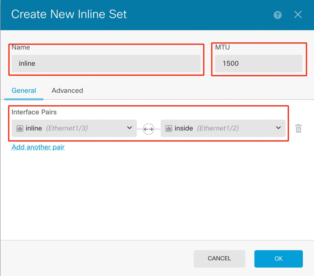 Interface Pairs
- To configure the advanced settings for the Inline Set, navigate to the Advanced Tab.
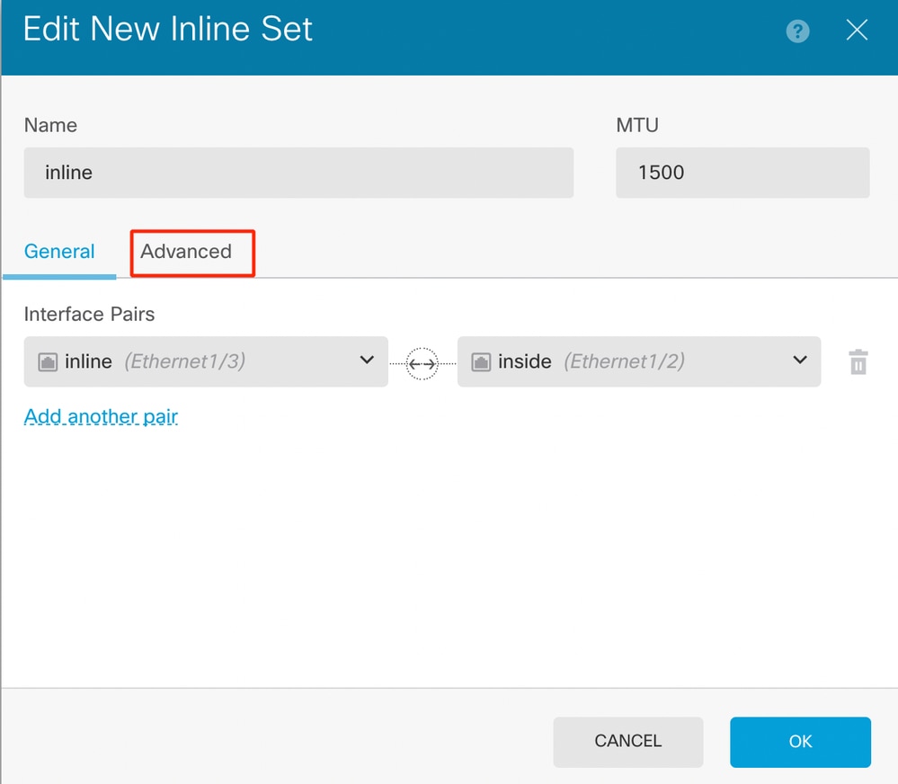 Advanced Settings
- Select the Mode as Inline. If Tap Mode is enabled, Snort Fail Open is disabled.
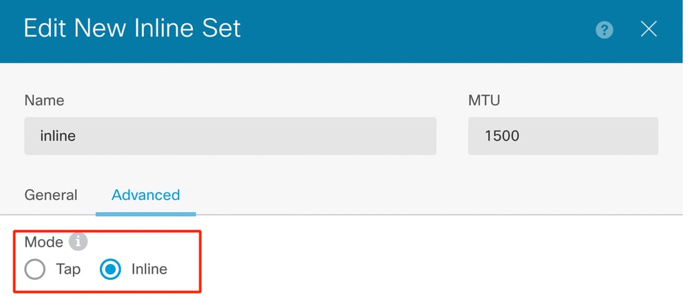 Mode Inline
- Snort Fail Open allows new and existing traffic to pass without inspection (enabled) or drop (disabled) when the Snort process is busy or down.
- Pick the desired Snort Fail Open settings.
- None, one, or both of the Busy and Down options can be set.
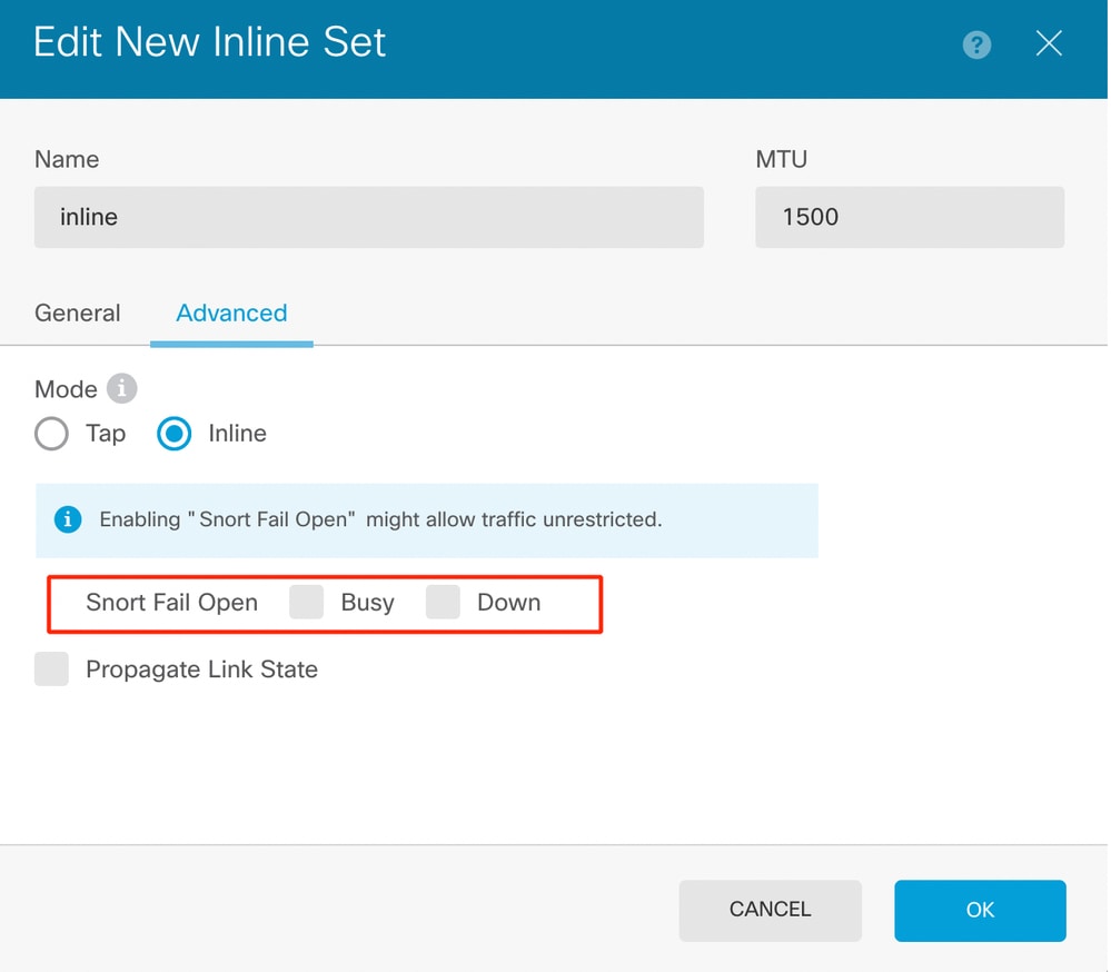 Snort Fail Open
- The Propagate Link State option automatically brings down the second interface in the Inline Pair when one of the interfaces goes down. When the downed interface comes back up, the second interface also automatically comes back up.
- Once everything is set, click Ok to save the configuration.
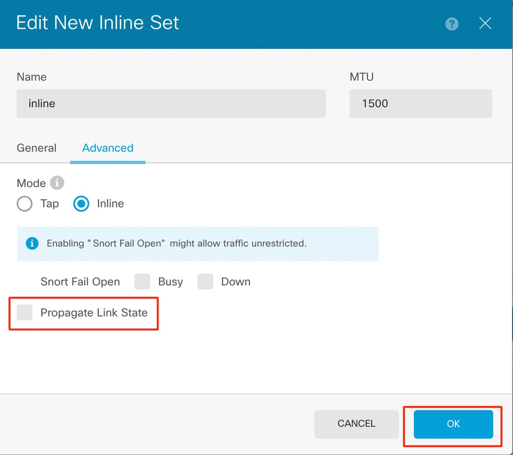 Propagate Link State
- To add this inline set to a security zone, navigate to Objects > Security Zones.
- Click Add to create a new security zone.
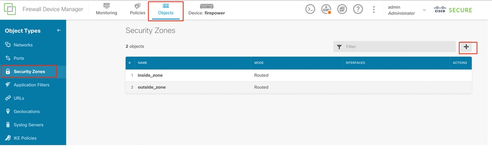 Add Security Zone
- Set a Name, select the mode as Inline and add the interfaces of the Inline Set. Then click OK to save.
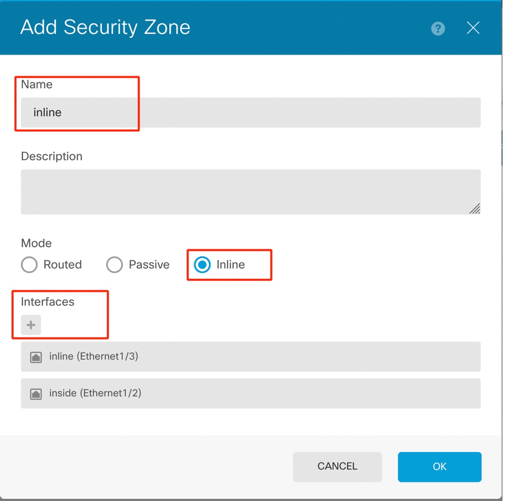 Add Interfaces
- Navigate to Deployment tab and Deploy the changes.
Modify or Delete an Inline Set
Edit and Delete actions are available for the Inline Sets.
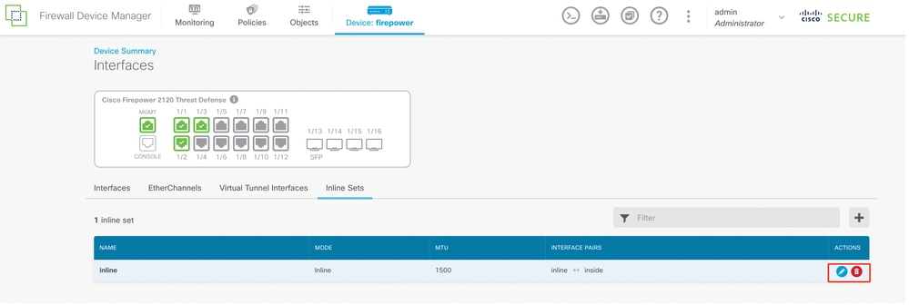 Actions of Inline Set
 Feedback