How to Populate Dynamic Routes Using Reverse Route Injection
Available Languages
Contents
Introduction
Reverse Route Injection (RRI) is used to populate the routing table of an internal router running Open Shortest Path First (OSPF) protocol or Routing Information Protocol (RIP) for remote VPN Clients or LAN-to-LAN sessions. RRI was introduced into versions 3.5 and later of the VPN 3000 Concentrator Series (3005 - 3080). RRI is not included on the VPN 3002 Hardware Client since it is treated as a VPN Client and not a VPN Concentrator. Only VPN Concentrators can advertise RRI routes. The VPN 3002 Hardware Client must run versions 3.5 or later of the code in order to inject Network Extension Routes back to the main VPN Concentrator.
Prerequisites
Requirements
There are no specific requirements for this document.
Components Used
The information in this document is based on these software and hardware versions:
-
Cisco VPN 3000 Concentrator with Software Version 3.5
-
Cisco 2514 Router running Cisco IOS® Software Release 12.2.3
-
Cisco VPN 3002 Hardware Client with Software Version 3.5 or later
The information in this document was created from the devices in a specific lab environment. All of the devices used in this document started with a cleared (default) configuration. If your network is live, make sure that you understand the potential impact of any command.
Conventions
For more information on document conventions, refer to the Cisco Technical Tips Conventions.
Background Information
There are four ways that RRI can be used:
-
VPN Software Clients inject their assigned IP address as hosts routes.
-
A VPN 3002 Hardware Client connects using Network Extension Mode (NEM) and injects its protected network address. (Note that a VPN 3002 Hardware Client in in Port Address Translation (PAT) mode is treated just like a VPN Client.)
-
LAN-to-LAN remote network definitions are the injected routes. (This can be a single network or network list.)
-
RRI provides a hold-down route for VPN Client pools.
When RRI is used, either RIP or OSPF can be used to advertise these routes. With earlier versions of VPN Concentrator code, LAN-to-LAN sessions can use network autodiscovery. However, this process can only use RIP as its advertising routing protocol.
Note: RRI cannot be used with Virtual Router Redundancy Protocol (VRRP) since both the Master and backup servers advertise the RRI routes. This can cause routing problems. Registered customers can get more details on this issue in Cisco bug ID CSCdw30156 (registered customers only) .
Configure
In this section, you are presented with the information to configure the features described in this document.
Note: Use the Command Lookup Tool (registered customers only) to obtain more information on the commands used in this section.
Network Diagram
This document uses this network setup:
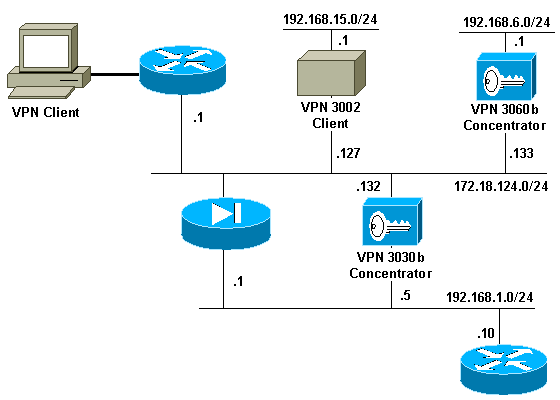
Configurations
This document uses these configurations:
| Router Configuration |
|---|
2514-b#show version Cisco Internetwork Operating System Software IOS (tm) 2500 Software (C2500-IK8OS-L), Version 12.2(3), RELEASE SOFTWARE (fc1) Copyright (c) 1986-2001 by cisco Systems, Inc. Compiled Wed 18-Jul-01 20:14 by pwade Image text-base: 0x0306B450, data-base: 0x00001000 2514-b#write terminal Building configuration... Current configuration : 561 bytes ! version 12.2 service timestamps debug uptime service timestamps log uptime no service password-encryption ! hostname 2514-b ! ip subnet-zero ! ip ssh time-out 120 ip ssh authentication-retries 3 ! interface Ethernet0 ip address 192.168.1.10 255.255.255.0 ! interface Ethernet1 no ip address shutdown ! router rip version 2 network 192.168.1.0 ! ip classless ip route 0.0.0.0 0.0.0.0 192.168.1.1 ip http server ! line con 0 line aux 0 line vty 0 4 ! end |
VPN 3000 Concentrator Configuration Using RIPv2
In order to advertise the RRI learned routes, you must have outbound RIP (at a minimum) enabled on the private interface of the local VPN Concentrator (represented by VPN 3030b in the network diagram). Network autodiscovery requires both inbound and outbound RIP to be enabled. Client RRI can be used on all VPN Clients that connect to the VPN Concentrator (such as VPN, Layer 2 Tunnel Protocol (L2TP), Point-to-Point Tunneling Protocol (PPTP), and so on).
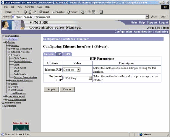
Client Reverse Route Injection
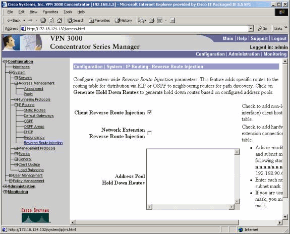
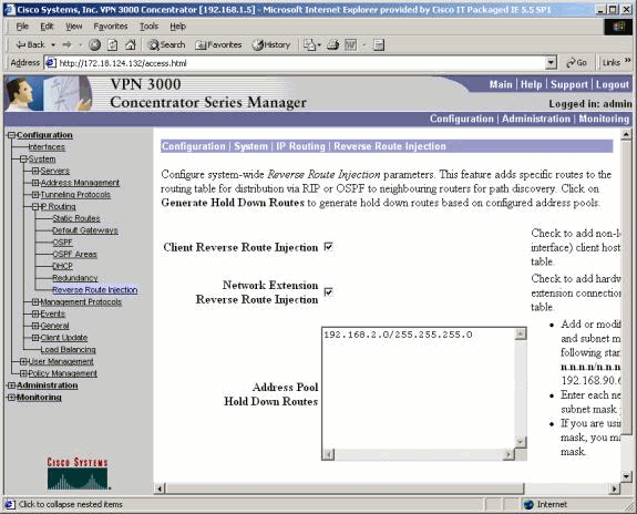
Client RRI can be used on all VPN Clients connecting to the VPN Concentrator. In order to configure Client RRI, go to Configuration > System > IP Routing > Reverse Route Injection and select the option for Client Reverse Route Injection.
Note: The VPN Concentrator has a group and user defined as well as a client pool of 192.168.3.1 - 192.168.3.254. See Verify / Test RIPv2 for more routing table information.
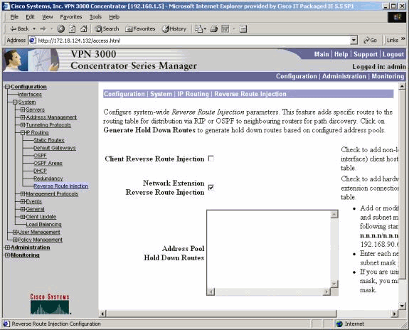
Network Extension RRI (VPN 3002 Client in NEM only)
In order to configure Network Extension RRI for the VPN 3002 Client, go to Configuration > System > IP Routing > Reverse Route Injection and select the option for Network Extension Reverse Route Injection.
Note: The VPN 3002 Client must run 3.5 or later code for Network Extension RRI to work. See Verify / Test NEM RRI for routing table information.
LAN-to-LAN Network Autodiscovery
This is a LAN-to-LAN session with a remote peer of 172.18.124.133 that covers network 192.168.6.0/24 on the local LAN. Within the LAN-to-LAN definition, (select Configuration > System > Tunneling Protocols > IPSec > LAN-to-LAN > Routing), network autodiscovery is used instead of network lists.
Note: Remember that only RIP can be used to advertise out the remote networks address when using network autodiscovery. In this case, normal autodiscovery is used instead of RRI. See Verify / Test LAN-to-LAN Network Autodiscovery for routing table information.
LAN-to-LAN Network RRI
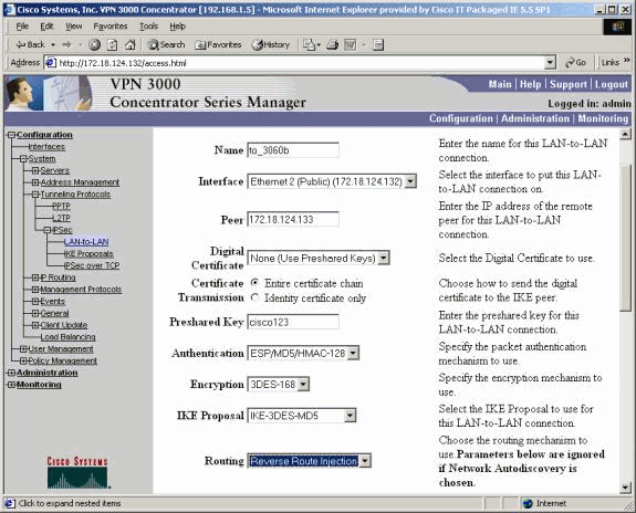
In order to configure for RRI, go to Configuration > System > Tunneling Protocols > IPSec. In the LAN-to-LAN definition, use the pull-down menu to set the Routing field to Reverse Route Injection so that the routes defined in the LAN-to-LAN session are passed on to the RIP or OSPF process. Click Apply to save the setting.
Note: When the LAN-to-LAN definition is set to use RRI, the VPN 3000 Concentrator advertises out the remote networks (single network or network list) so that the internal router is away from the remote network. See Verify / Test LAN-to-LAN Network RRI for routing table information.
In order to configure in CLI mode, refer to Verify that Routing is Correct for injecting the information of the remote LAN-to-LAN VPN networks into the OSPF running network.
Hold-Down Routes
Hold-down routes are used as place holders for routes to remote networks or VPN Client pools. For example, if a remote VPN peer fronts the 192.168.2.0/24 network, there are only a few ways that the local LAN is able to see that network:
-
The internal router (such as 2514-b in the sample router configuration) has a static route for 192.168.2.0/24 that points to the private address of the VPN Concentrator. This is an acceptable solution if you do no want to run RRI or if the VPN Concentrator does not support this feature.
-
You can use network autodiscovery. However, this pushes the 192.168.2.0/24 network into the local network only when the VPN tunnel is up. In short, the local network cannot start the tunnel since it has no routing knowledge of the remote network. Once the 192.168.2.0 remote network brings up the tunnel, it passes the network through the autodiscovery and then injects it into the routing process. Remember that this applies only to RIP; OSPF cannot be used in this case.
-
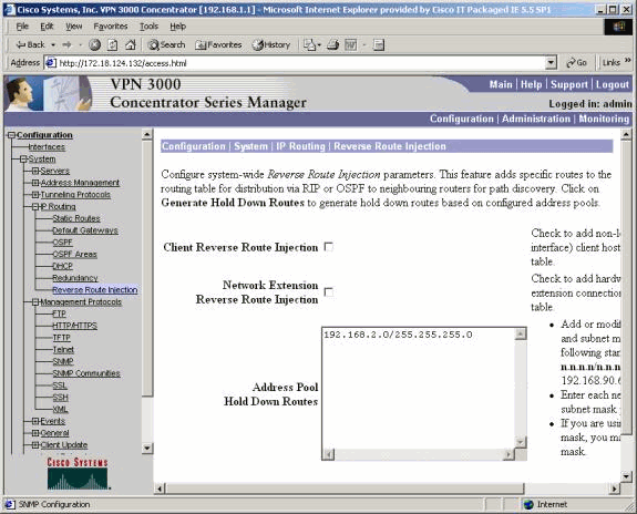
Using Address Pool Hold Down Routes always advertises the defined networks so that both the local and remote networks can bring up the tunnel if the tunnel does not exist.
In order to configure Address Pool Hold Down Routes, go to Configuration > System > IP Routing > Reverse Route Injection and input the address pool, as shown here. See Verify / Test Hold-Down Routes for routing table information.
Use OSPF With RRI
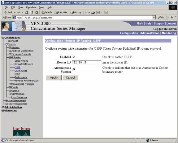
In order to use OSPF, go to Configuration > System > IP Routing > OSPF, then enter the Router ID (IP address). Select the options for Autonomous System and Enabled. Note that to push the RRI routes into the OSPF table, you need to make the OSPF process on the VPN 3000 Concentrator an autonomous system.
See Verify / Test OSPF With RRI for routing table information.
Verify
This section provides information you can use to confirm your configuration is working properly.
The Output Interpreter Tool (registered customers only) (OIT) supports certain show commands. Use the OIT to view an analysis of show command output.
Verify / Test RIPv2
Routing Table Before VPN Client Connection
The VPN Concentrator has a group and user defined, as well as a client pool of 192.168.3.1 - 192.168.3.254.
2514-b#show ip route
Codes: C - connected, S - static, I - IGRP, R - RIP, M - mobile, B - BGP
       D - EIGRP, EX - EIGRP external, O - OSPF, IA - OSPF inter area
       N1 - OSPF NSSA external type 1, N2 - OSPF NSSA external type 2
       E1 - OSPF external type 1, E2 - OSPF external type 2, E - EGP
       i - IS-IS, L1 - IS-IS level-1, L2 - IS-IS level-2, ia - IS-IS inter area
       * - candidate default, U - per-user static route, o - ODR
       P - periodic downloaded static route

Gateway of last resort is 192.168.1.1 to network 0.0.0.0

C    192.168.1.0/24 is directly connected, Ethernet0
S*   0.0.0.0/0 [1/0] via 192.168.1.1
Routing Table During VPN Client Connection
2514-b#show ip route
Codes: C - connected, S - static, I - IGRP, R - RIP, M - mobile, B - BGP
       D - EIGRP, EX - EIGRP external, O - OSPF, IA - OSPF inter area
       N1 - OSPF NSSA external type 1, N2 - OSPF NSSA external type 2
       E1 - OSPF external type 1, E2 - OSPF external type 2, E - EGP
       i - IS-IS, L1 - IS-IS level-1, L2 - IS-IS level-2, ia - IS-IS inter area
       * - candidate default, U - per-user static route, o - ODR
       P - periodic downloaded static route

Gateway of last resort is 192.168.1.1 to network 0.0.0.0

     172.18.0.0/24 is subnetted, 1 subnets
R       172.18.124.0 [120/1] via 192.168.1.5, 00:00:21, Ethernet0
C    192.168.1.0/24 is directly connected, Ethernet0
     192.168.3.0/32 is subnetted, 1 subnets
R       192.168.3.1 [120/1] via 192.168.1.5, 00:00:21, Ethernet0

!--- 192.168.3.1 is the client-assigned IP address !--- for the newly connected VPN Client.


S*   0.0.0.0/0 [1/0] via 192.168.1.1
Routing Table When Two Clients Are Connected
2514-b#show ip route
Codes: C - connected, S - static, I - IGRP, R - RIP, M - mobile, B - BGP
       D - EIGRP, EX - EIGRP external, O - OSPF, IA - OSPF inter area
       N1 - OSPF NSSA external type 1, N2 - OSPF NSSA external type 2
       E1 - OSPF external type 1, E2 - OSPF external type 2, E - EGP
       i - IS-IS, L1 - IS-IS level-1, L2 - IS-IS level-2, ia - IS-IS inter area
       * - candidate default, U - per-user static route, o - ODR
       P - periodic downloaded static route

Gateway of last resort is 192.168.1.1 to network 0.0.0.0

     172.18.0.0/24 is subnetted, 1 subnets
R       172.18.124.0 [120/1] via 192.168.1.5, 00:00:05, Ethernet0
C    192.168.1.0/24 is directly connected, Ethernet0
     192.168.3.0/32 is subnetted, 2 subnets
R       192.168.3.2 [120/1] via 192.168.1.5, 00:00:05, Ethernet0
R       192.168.3.1 [120/1] via 192.168.1.5, 00:00:05, Ethernet0
S*   0.0.0.0/0 [1/0] via 192.168.1.1
With host routes added for each VPN Client, it may be easier on the routing table to use a hold-down route for 192.168.3.0/24. In other words, it becomes a choice between 250 host routes that use Client RRI versus one network hold-down route.
Here is an example that shows use of a hold-down route:
Gateway of last resort is 192.168.1.1 to network 0.0.0.0

     172.18.0.0/24 is subnetted, 1 subnets
R       172.18.124.0 [120/1] via 192.168.1.5, 00:00:13, Ethernet0
C    192.168.1.0/24 is directly connected, Ethernet0
     192.168.3.0/24 is subnetted, 1 subnets
R       192.168.3.0 [120/1] via 192.168.1.5, 00:00:14, Ethernet0

!--- There is one entry for the 192.168.3.x network, !--- rather than 1 for each host for the VPN pool.


S*   0.0.0.0/0 [1/0] via 192.168.1.1
Verify / Test NEM RRI
Here is the router's routing table:
2514-b#show ip route
Codes: C - connected, S - static, I - IGRP, R - RIP, M - mobile, B - BGP
       D - EIGRP, EX - EIGRP external, O - OSPF, IA - OSPF inter area
       N1 - OSPF NSSA external type 1, N2 - OSPF NSSA external type 2
       E1 - OSPF external type 1, E2 - OSPF external type 2, E - EGP
       i - IS-IS, L1 - IS-IS level-1, L2 - IS-IS level-2, ia - IS-IS inter area
       * - candidate default, U - per-user static route, o - ODR
       P - periodic downloaded static route

Gateway of last resort is 192.168.1.1 to network 0.0.0.0

R    192.168.15.0/24 [120/1] via 192.168.1.5, 00:00:05, Ethernet0

 !--- This is the network behind the VPN 3002 Client.

     172.18.0.0/24 is subnetted, 1 subnets
R       172.18.124.0 [120/1] via 192.168.1.5, 00:00:05, Ethernet0
C    192.168.1.0/24 is directly connected, Ethernet0
S*   0.0.0.0/0 [1/0] via 192.168.1.1
Verify / Test LAN-to-LAN Network Autodiscovery
Routing Table Before LAN-to-LAN Connection (Network Autodiscovery)
2514-b#show ip route
Codes: C - connected, S - static, I - IGRP, R - RIP, M - mobile, B - BGP
       D - EIGRP, EX - EIGRP external, O - OSPF, IA - OSPF inter area
       N1 - OSPF NSSA external type 1, N2 - OSPF NSSA external type 2
       E1 - OSPF external type 1, E2 - OSPF external type 2, E - EGP
       i - IS-IS, L1 - IS-IS level-1, L2 - IS-IS level-2, ia - IS-IS inter area
       * - candidate default, U - per-user static route, o - ODR
       P - periodic downloaded static route

Gateway of last resort is 192.168.1.1 to network 0.0.0.0

     172.18.0.0/24 is subnetted, 1 subnets
R       172.18.124.0 [120/1] via 192.168.1.5, 00:00:07, Ethernet0
C    192.168.1.0/24 is directly connected, Ethernet0
S*   0.0.0.0/0 [1/0] via 192.168.1.1
Routing Table (Internal Router) During LAN-to-LAN (Network Autodiscovery)
2514-b#show ip route
Codes: C - connected, S - static, I - IGRP, R - RIP, M - mobile, B - BGP
       D - EIGRP, EX - EIGRP external, O - OSPF, IA - OSPF inter area
       N1 - OSPF NSSA external type 1, N2 - OSPF NSSA external type 2
       E1 - OSPF external type 1, E2 - OSPF external type 2, E - EGP
       i - IS-IS, L1 - IS-IS level-1, L2 - IS-IS level-2, ia - IS-IS inter area
       * - candidate default, U - per-user static route, o - ODR
       P - periodic downloaded static route

Gateway of last resort is 192.168.1.1 to network 0.0.0.0

     172.18.0.0/24 is subnetted, 1 subnets
R       172.18.124.0 [120/1] via 192.168.1.5, 00:00:04, Ethernet0
R    192.168.6.0/24 [120/2] via 192.168.1.5, 00:00:04, Ethernet0
C    192.168.1.0/24 is directly connected, Ethernet0
S*   0.0.0.0/0 [1/0] via 192.168.1.1
Note: RIP has a three-minute hold-down timer. Even though the LAN-to-LAN session dropped, it takes approximately three minutes for the route to actually time out.
Verify / Test LAN-to-LAN Network RRI
Here is the router's routing table:
Gateway of last resort is 192.168.1.1 to network 0.0.0.0

     172.18.0.0/24 is subnetted, 1 subnets
R       172.18.124.0 [120/1] via 192.168.1.5, 00:00:11, Ethernet0
R    192.168.6.0/24 [120/1] via 192.168.1.5, 00:00:11, Ethernet0
C    192.168.1.0/24 is directly connected, Ethernet0
S*   0.0.0.0/0 [1/0] via 192.168.1.1
Because 192.168.6.0/24 was used in the LAN-to-LAN remote network list, this information is passed off to the routing process. If there was a network list of 192.168.6.x, .7.x, and .8.x (all /24), then the router's routing table would look like this:
R    192.168.8.0/24 [120/1] via 192.168.1.5, 00:00:02, Ethernet0
     172.18.0.0/24 is subnetted, 1 subnets
R       172.18.124.0 [120/1] via 192.168.1.5, 00:00:02, Ethernet0
R    192.168.6.0/24 [120/1] via 192.168.1.5, 00:00:02, Ethernet0
R    192.168.7.0/24 [120/1] via 192.168.1.5, 00:00:02, Ethernet0
C    192.168.1.0/24 is directly connected, Ethernet0
S*   0.0.0.0/0 [1/0] via 192.168.1.1
...
Verify / Test Hold-Down Routes
In this example, 192.168.2.0 is the remote network that you want as a place holder. By default, the routing table on the internal router after enabling the hold-down pool shows:
2514-b#show ip route
Codes: C - connected, S - static, I - IGRP, R - RIP, M - mobile, B - BGP
       D - EIGRP, EX - EIGRP external, O - OSPF, IA - OSPF inter area
       N1 - OSPF NSSA external type 1, N2 - OSPF NSSA external type 2
       E1 - OSPF external type 1, E2 - OSPF external type 2, E - EGP
       i - IS-IS, L1 - IS-IS level-1, L2 - IS-IS level-2, ia - IS-IS inter area
       * - candidate default, U - per-user static route, o - ODR
       P - periodic downloaded static route

Gateway of last resort is 192.168.1.1 to network 0.0.0.0

     172.18.0.0/24 is subnetted, 1 subnets
R       172.18.124.0 [120/1] via 192.168.1.5, 00:00:05, Ethernet0
C    192.168.1.0/24 is directly connected, Ethernet0
R    192.168.2.0/24 [120/1] via 192.168.1.5, 00:00:06, Ethernet0
S*   0.0.0.0/0 [1/0] via 192.168.1.1
Note that the 172.18.124.0 route is actually the outside public interface network of the VPN 3000 Concentrator. If you do not want this route to be learned via the private interface of the VPN Concentrator, add a static route or route filter to rewrite / block this learned route.
Using a static route that points to the Corporate Firewall at 192.168.1.1 now shows the routing table as using ip route 172.18.124.0 255.255.255.0 192.168.1.1, as shown here:
2514-b#show ip route
Codes: C - connected, S - static, I - IGRP, R - RIP, M - mobile, B - BGP
       D - EIGRP, EX - EIGRP external, O - OSPF, IA - OSPF inter area
       N1 - OSPF NSSA external type 1, N2 - OSPF NSSA external type 2
       E1 - OSPF external type 1, E2 - OSPF external type 2, E - EGP
       i - IS-IS, L1 - IS-IS level-1, L2 - IS-IS level-2, ia - IS-IS inter area
       * - candidate default, U - per-user static route, o - ODR
       P - periodic downloaded static route

Gateway of last resort is 192.168.1.1 to network 0.0.0.0

     172.18.0.0/24 is subnetted, 1 subnets
S       172.18.124.0 [1/0] via 192.168.1.1
C    192.168.1.0/24 is directly connected, Ethernet0
R    192.168.2.0/24 [120/1] via 192.168.1.5, 00:00:28, Ethernet0
S*   0.0.0.0/0 [1/0] via 192.168.1.1
Verify / Test OSPF With RRI
2514-b#show ip route
Codes: C - connected, S - static, I - IGRP, R - RIP, M - mobile, B - BGP
       D - EIGRP, EX - EIGRP external, O - OSPF, IA - OSPF inter area
       N1 - OSPF NSSA external type 1, N2 - OSPF NSSA external type 2
       E1 - OSPF external type 1, E2 - OSPF external type 2, E - EGP
       i - IS-IS, L1 - IS-IS level-1, L2 - IS-IS level-2, ia - IS-IS inter area
       * - candidate default, U - per-user static route, o - ODR
       P - periodic downloaded static route

Gateway of last resort is 192.168.1.1 to network 0.0.0.0

O E2 192.168.15.0/24 [110/20] via 192.168.1.5, 00:07:33, Ethernet0
O E2 192.168.6.0/24 [110/20] via 192.168.1.5, 00:07:33, Ethernet0
C    192.168.1.0/24 is directly connected, Ethernet0
O E2 192.168.2.0/24 [110/20] via 192.168.1.5, 00:07:33, Ethernet0
     192.168.3.0/32 is subnetted, 1 subnets
O E2    192.168.3.1 [110/20] via 192.168.1.5, 00:00:08, Ethernet0
S*   0.0.0.0/0 [1/0] via 192.168.1.1
Here are the values for this example:
-
192.168.15.0 is the network extension mode for the VPN 3002 Concentrator.
-
192.168.6.0 is the network for the LAN-to-LAN session.
-
192.168.2.0 is a hold-down route.
-
192.168.3.1 is a client-injected route.
Verify Routing Table Information in the VPN Concentrator
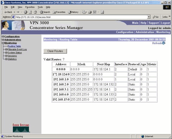
Ensure that the routes show up in the routing table on the local VPN Concentrator. In order to check this, go to Monitoring > Routing Table.
You can see the routes learned via RRI as static routes off the public interface (interface #2). In this example, the routes are:
-
The hold-down route, 192.168.2.0, shows the next hop being that of the IP address of the public interface, 172.18.124.132.
-
The VPN Client that was assigned the 192.168.3.1 address has its next hop to the default gateway for the VPN Concentrator on the public network (172.18.124.1).
-
The LAN-to-LAN connection at 192.168.6.0 shows its peer address of 172.18.124.133, and the same holds true for the VPN 3002 Concentrator in Network Extension mode.
Troubleshoot
There is currently no specific troubleshooting information available for this configuration.
Related Information
Revision History
| Revision | Publish Date | Comments |
|---|---|---|
1.0 |
02-Feb-2006 |
Initial Release |
 Feedback