Handling Traffic Using VN-Link
Available Languages
Contents
Introduction
Cisco VN-Link in hardware is a hardware-based method of handling traffic to and from a virtual machine on a server with a VIC adapter. This method is sometimes referred to as pass-through switching. This solution replaces software-based switching with ASIC-based hardware switching and improves performance.
The distributed virtual switch (DVS) framework delivers VN-Link in hardware features and capabilities for virtual machines on Cisco UCS servers with VIC adapters. This approach provides an end-to-end network solution to meet the new requirements created by server virtualization. With VN-link in hardware, Layer 2 traffic between two VMs on the same host is not locally switched on the DVS but it sent upstream to the UCs-6100 for the policy application and switching. Switching occurs in the fabric interconnect (hardware). As a result, network policies can be applied to traffic between virtual machines. This capability provides consistency between physical and virtual servers.
Note: VMotion is supported in the VN-Link Hardware.
Prerequisites
Requirements
Ensure that you meet these requirements before you attempt this configuration:
-
Enterprise Plus License must be installed on the ESX hosts. This is required for DVS switching function.
Components Used
The information in this document is based on these software and hardware versions. All components in the chassis and blades have been upgraded to 1.3.1c.
-
Cisco UCS 6120XP 2x N10-S6100
-
1 N20-C6508
-
2x N20-B6620-2
-
Cisco UCS VIC M81KR Virtual Interface Card 2x N20-AC0002
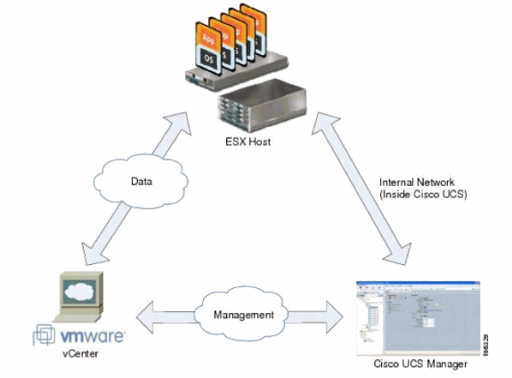
These three main components must be connected for VN-Link in hardware to work:
-
VMware ESX Host
A server with the VMware ESX installed. It contains a datastore and the virtual machines. The ESX host must have a Cisco M81KR VIC installed, and it must have uplink data connectivity to the network for communication with VMware vCenter.
-
VMware vCenter
Windows-based software used to manage one or more ESX hosts. VMware vCenter must have connectivity to the UCS management port for management plane integration, and uplink data connectivity to the network for communication with the ESX Host. A vCenter extension key provided by Cisco UCS Manager must be registered with VMware vCenter before the Cisco UCS instance can be acknowledged.
-
Cisco UCS Manager
The Cisco UCS management software that integrates with VMware vCenter to handle some of the network-based management tasks.
The information in this document was created from the devices in a specific lab environment. All of the devices used in this document started with a cleared (default) configuration. If your network is live, make sure that you understand the potential impact of any command.
Cisco UCS Manager must have management port connectivity to VMware vCenter for management plane integration. It also provides a vCenter extension key that represents the Cisco UCS identity. The extension key must be registered with VMware vCenter before the Cisco UCS instance can be acknowledged.
Conventions
Refer to the Cisco Technical Tips Conventions for more information on document conventions.
Configure
In this section, you are presented with the information to configure the features described in this document.
Note: Use the Command Lookup Tool (registered customers only) to obtain more information on the commands used in this section.
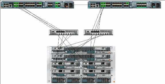
Network Diagram
Network Configuration VLAN and IP Ranges Used
-
UCS Management VLAN 8—172.21.60.64/26
-
VC/ESX Management VLAN 103—172.21.61.192/26
-
Public VLAN 100—10.21.60.0/24
-
VLAN numbers used—8,100,103
vCenter IP
-
- 172.21.61.222
Host IPs
-
ESX Hosts
-
- pts-01 - 172.21.61.220
-
- pts-02 - 172.21.61.221
VM IPs
-
RHEL5.5 VMs
-
- rhel5x-1 - 172.21.61.225
-
- rhel5x-2 - 172.21.61.226
-
- rhel5x-2 - 172.21.61.227
-
- rhel5x-2 - 172.21.61.228
-
- rhel5x-2 - 172.21.61.229
-
Ubuntu VMs
-
- ubuntu10x-1 - 10.21.60.152
-
- ubuntu10x-2 - 10.21.60.153
This figure shows the three main components of VN-Link in hardware and the methods by which they are connected:
Chassis Discovery Policy

Configurations
Complete these steps in order to create a Dynamic vNIC Connection Policy.
-
In the Navigation pane, click the LAN tab.
-
On the LAN tab, choose LAN > Policies.
-
Expand the node for the organization where you want to create the policy. If the system does not include multi-tenancy, expand the root node.
-
Right-click the Dynamic vNIC Connection Policies node and choose Create Dynamic vNIC Connection Policy.
-
In the Create Dynamic vNIC Connection Policy dialog box, complete these fields:
-
The name of the policy—This name can be between 1 and 16 alphanumeric characters. You cannot use spaces or any special characters, and you cannot change this name after the object has been saved.
-
Description field—A description of the policy. Cisco recommends that you include information about where and when the policy should be used.
-
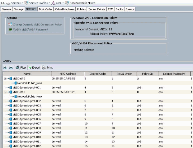
Number of Dynamic vNICs field—The number of dynamic vNICs that this policy affects. The actual number of dynamic vNICs that can be used for VN-lInk in HW is less since you have to account for static vNICs and vHBAs. Typically you need to apply the formula 15 x No of uplinks - 6. Hence it would be 54 for four uplinks, 24 for two uplinks.
-
Adapter Policy drop-down list— The adapter profile associated with this policy. The profile must already exist to be included in the drop-down list.
-
Protection field—This field is always set to protected because failover mode is always enabled for virtual NICs.
-
-
Click OK.
-
If Cisco UCS Manager GUI displays a confirmation dialog box, click Yes.
Service Profile configured with Dynamic vNICs.
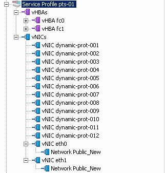
This document uses these configurations:
Dynamic vNICs defined in Service Profile
QOS Policy Definition
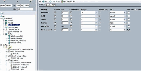
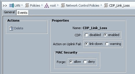
The Network Control and QOS policy has been configured accordingly. This comes into play later when you use iPerf from the VMs to show egress rate limiting.

Network Control Policy is used in this example:
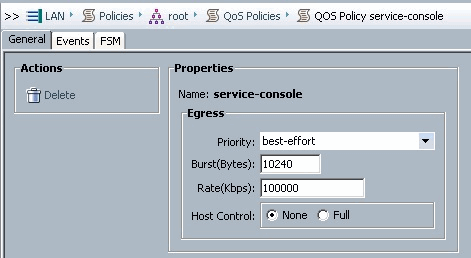
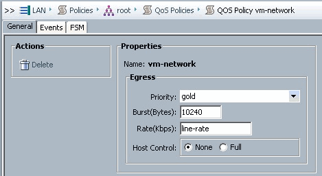
QOS Policy is used in the example:
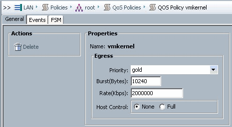
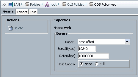
Boot Policy is used for this example. The VMFS shared volume is configured on the SAN, but the systems are local disk boot systems.

Click the VM tab.
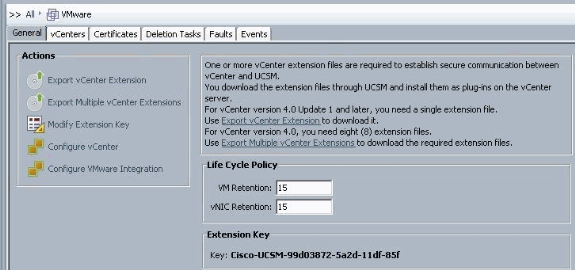
Export a vCenter Extension File from Cisco UCS Manager
You can either generate one extension file or a set of nine extension files, which depends on the version of VMware vCenter. Complete these steps:
-
In the Navigation pane, click the VM tab.
-
On the VM tab, expand the All node.
-
On the VM tab, click VMWare.
-
In the Work pane, click the General tab.
-
In the Actions area, click one of these links:
-
Export vCenter Extension—For vCenter version 4.0 update 1 and later.
-
Export Multiple vCenter Extensions—For vCenter version 4.0.
-
-
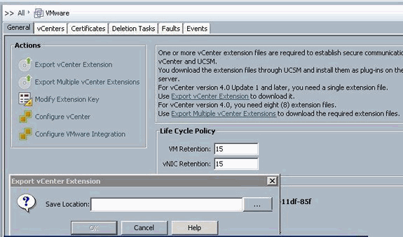
In the Export vCenter Extension dialog box, complete these steps::
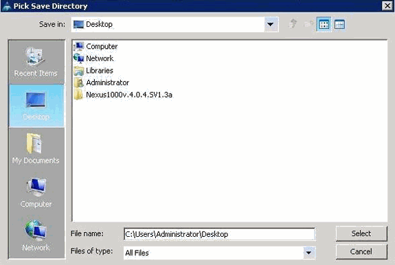
Cisco UCS Manager generates the extension file(s) and saves them to the specified location.
-
In the Save Location field, enter the path to the directory where you want to save the extension file or files. If you do not know the path, click the ... button and browse to the location.
-
Click OK.
What to Do Next
-
Register the vCenter extension file or files in VMware vCenter.
-
Registering a vCenter Extension File in VMware vCenter
-
-
In VMware vCenter, the vCenter extension files are called plug-ins.
Export the vCenter extension file(s) from Cisco UCS Manager. Ensure that the exported vCenter extension files are saved to a location that can be reached by VMware vCenter.
Complete these steps:
-
In VMware vCenter, choose Plug-ins > Manage Plug-ins.
The vCenter extension file registers as an available VMware vCenter plug-in. You do not need to install the plug-in; leave it in the available state. If you are registering multiple vCenter extension files, repeat this procedure until all files are registered.

-
Right-click any empty space below the Available Plug-ins section of the Plug-in Manager dialog box and click New Plug-in.
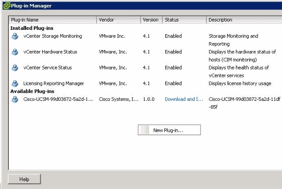
Import Extension Key previously saved from the desktop.
-
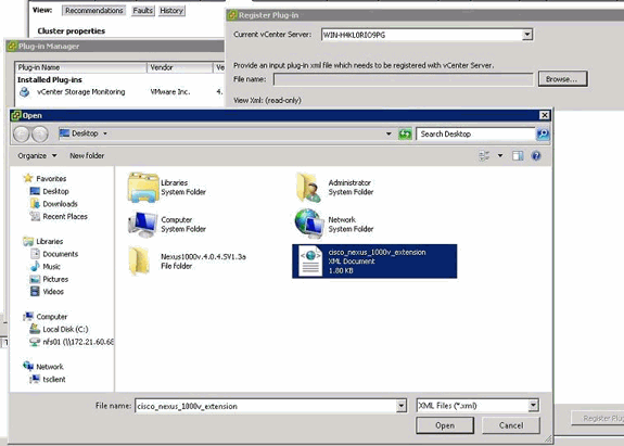
Click Browse and navigate to the location where the vCenter extension file(s) are saved.
-
Choose a vCenter extension file and click Open.
-
Click Register Plug-in.
-
If the Security Warning dialog box appears, click Ignore.
-
Click OK.
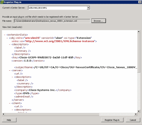
Now configure vCenter communication with UCSM.
Define a VMware vCenter Distributed Virtual Switch
This procedure directly follows the steps in Page 1: Establishing the Connection to vCenter Server. It describes how to define the components of a distributed virtual switch in VMware vCenter through the Configure VMware Integration wizard.
-
In the vCenter Server area, complete these fields in order to define the connection to VMware vCenter:
-
Name Field—vCenter Server Name field. The user-defined name for the vCenter server. This name can be between 1 and 16 alphanumeric characters. You cannot use spaces or any special characters, and you cannot change this name after the object has been saved.
-
Description field—The description of the vCenter server.
-
vCenter Server Hostname or IP Address field—The hostname or IP address of the vCenter server.
Note: If you use a hostname rather than an IP address, you must configure a DNS server in Cisco UCS Manager.
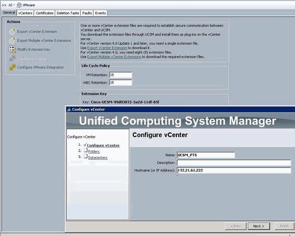
Once this relevant information is provided, click Next for the UCSM to try to establish communication to vCenter. A good indication that communication is successful is to see the Key being generated.

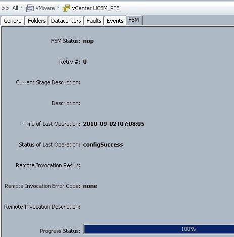
Also check the FSM for a configSuccess and nop state.
-
-
In the Datacenter area, complete these fields in order to create the datacenter in VMware vCenter:
-
Name Field — vCenter Datacenter Name. The name of the vCenter Datacenter. This name can be between 1 and 16 alphanumeric characters. You cannot use spaces or any special characters, and you cannot change this name after the object has been saved.
-
Description field—The user-defined description of the Datacenter.
Note: In this document, a Datacenter is not created from UCSM, but you start by creating Folders.
-
-
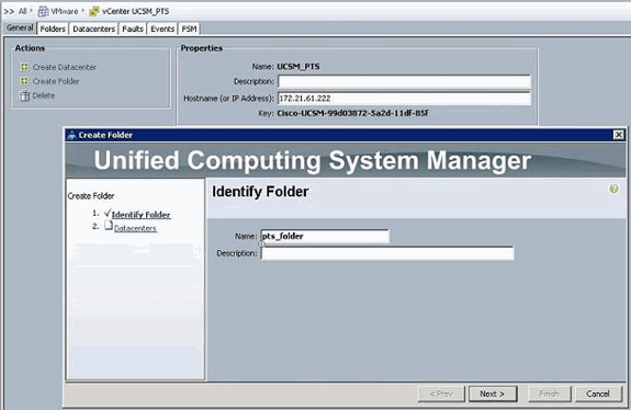
In the DVS Folder area, complete these fields in order to create a folder to contain the distributed virtual switch in VMware vCenter:
-
Name Field—Folder Name field. The name of the folder that contains the distributed virtual switch (DVS). This name can be between 1 and 16 alphanumeric characters. You cannot use spaces or any special characters, and you cannot change this name after the object has been saved.
-
Description field—The user-defined description of the folder.
-
-
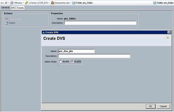
In the DVS area, complete these fields in order to create the distributed virtual switch in VMware vCenter:
-
Name Field—DVS Name field. The name of the DVS. This name can be between 1 and 16 alphanumeric characters. You cannot use spaces or any special characters, and you cannot change this name after the object has been saved.
-
Description field—The user-defined description of the DVS. DVS field
-
Admin state—This can be:
* disable
* enable
If you disable the DVS, Cisco UCS Manager does not push any configuration changes related to the DVS to VMware vCenter.
-
Port Profiles
Port profiles contain the properties and settings used to configure virtual interfaces in Cisco UCS for VN-Link in hardware. The port profiles are created and administered in Cisco UCS Manager.
Note: There is no clear visibility into the properties of a port profile from VMware vCenter.
In VMware vCenter, a port profile is represented as a port group. Cisco UCS Manager pushes the port profile names to vCenter, which displays the names as port groups. None of the specific networking properties or settings in the port profile are visible in VMware vCenter.
After a port profile is created, assigned to, and actively used by one or more DVSes, any changes made to the networking properties of the port profile in Cisco UCS Manager are immediately applied to those DVSes. You must configure at least one port profile client for a port profile, if you want Cisco UCS Manager to push the port profile to VMware vCenter.
Port Profile Clients
The port profile client determines the DVSes to which a port profile is applied. By default, the port profile client specifies that the associated port profile applies to all DVSes in the vCenter. But, you can configure the client to apply the port profile to all DVSes in a specific datacenter or datacenter folder, or only to one DVS.
Complete these steps in order to create a Port Profile:
-
In the Navigation pane, click the VM tab.
-
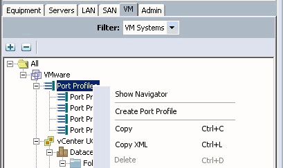
On the VM tab, choose All > VMWare.
-
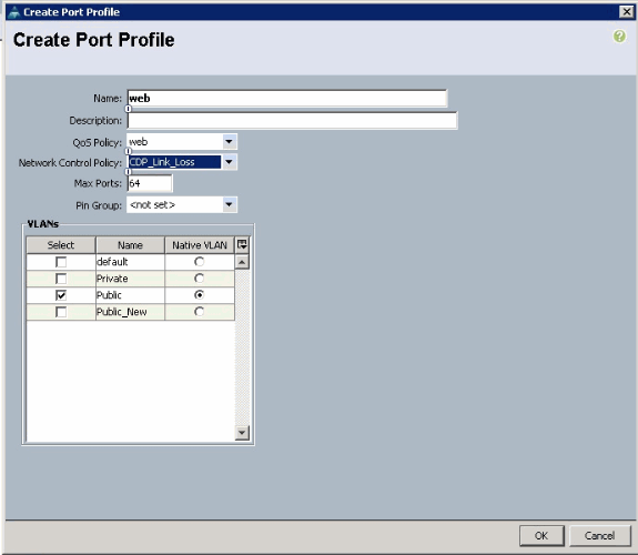
Right-click the Port Profiles node and choose Create Port Profile.
-
In the Create Port Profile dialog box, complete these fields:
-
Name field— The user-defined name for the port profile.This name can be between 1 and 16 alphanumeric characters. You cannot use spaces or any special characters, and you cannot change this name after the object has been saved.
-
Description field—The user-defined description of the Port Profile.
-
QoS Policy drop-down list—The quality of service policy associated with this port profile.
-
Network Control Policy drop-down list—The network control policy associated with this port profile.
-
Max Ports field—The maximum number of ports that can be associated with this port profile. The default is 64 ports. The maximum number of ports that can be associated with a single distributed virtual switch (DVS) is 4096. If the DVS has only one associated port profile, that port profile can be configured with up to 4096 ports. However, if the DVS has more than one associated port profile, the total number of ports associated with all of those port profiles combined cannot exceed 4096.
-
Pin Group drop-down list—The pin group associated with this port profile.
-
-
In the VLANs area, complete these fields:
-
Select column—Check the check box in this column for each VLAN you want to use.
-
Name column—The name of the VLAN
-
Native VLAN column—To designate one of the VLANs as the native VLAN, click the radio button in this column.
-
-
Click Finish.
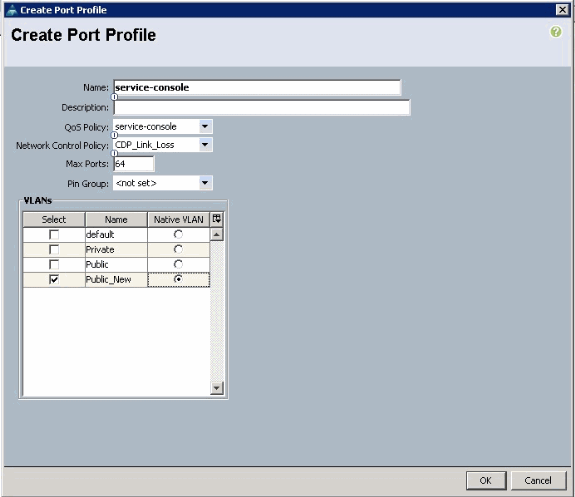
Do the previous steps for each Port Profile.
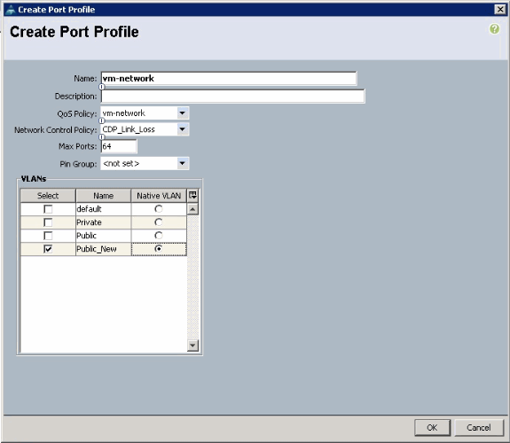
Do the previous steps for each Port Profile.
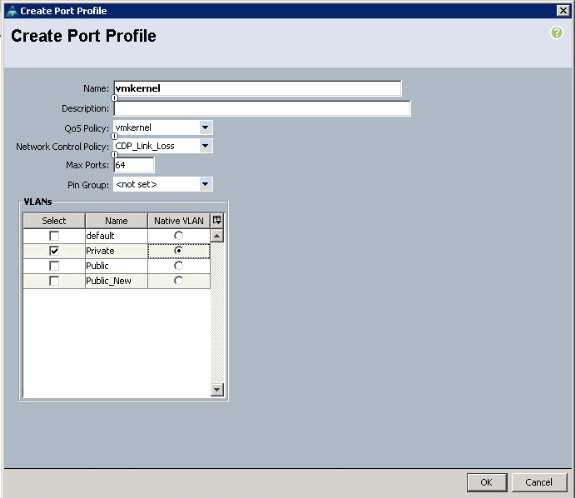
Do the previous steps for each Port Profile.
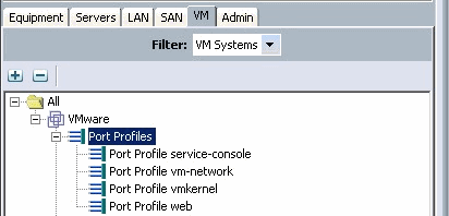
You see Port Profiles similar to these screen shots once you are done.

You can now go through and apply Port Profiles to the Port Profile Clients.
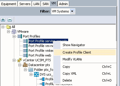
You can now go through and apply Port Profiles to the Port Profile Clients.
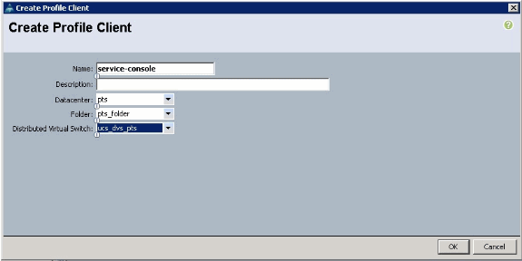
You can now go through and apply Port Profiles to the Port Profile Clients.
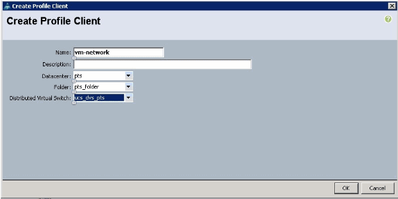
You can now go through and apply Port Profiles to the Port Profile Clients.
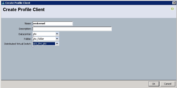
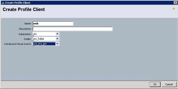
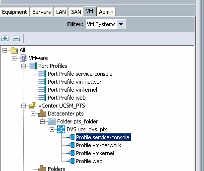
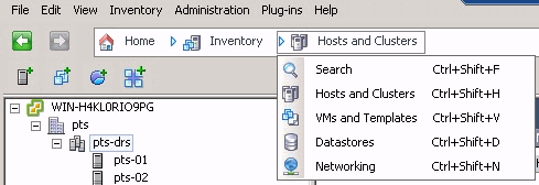
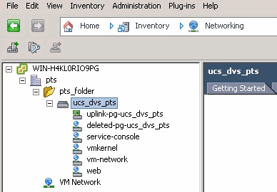
You can now confirm all the port profiles are created successfully on the vCenter. Click Hosts and Clusters and from the drop-down menu, choose Networking.
All the port profiles created from the UCSM VM tab are now reflected in the respective folder in vCenter.
At this stage you can now install the respective VEMs on the ESX hosts. Download the Nexus1K software package from Cisco Software Download (registered customers only) .
Unzip the file downloaded from CCO, and when unzipped the folder would contain these directories and files:
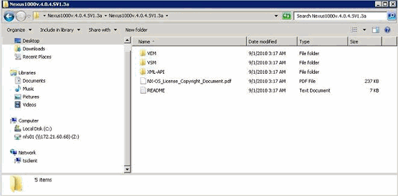
Make sure to read the README.TXT to match the version of VEM to use with respects to the ESX/ESXi version and build number being used.
As an example, the version of the ESX build being used in this document is :

So based on this previous build information, you see the respective version of VEM to use from the README.TXT file. For example:

Use some file transfer mechanism in order to get the respective .vib file to the ESX hosts and use this command in order to install the VEM.
root@pts-01 tmp]# esxupdate -b cross_cisco-vem-v121-4.0.4.1.3.1.0-2.0.3.vib update
Unpacking cross_cisco-vem-v121-esx_4.0.4.1.3.1.0-2.0.3
################################################################### [100%]
Installing cisco-vem-v121-esx
################################################################### [100%]
Running [/usr/sbin/vmkmod-install.sh]...
ok.

Check status of the VEM to confirm the modules loaded successfully.
[root@pts-01 tmp]# vmkload_mod -l | grep vem
vem-v121-svs-mux         2    32
vem-v121-pts             0    92
root@pts-02 tmp]# esxupdate -b cross_cisco-vem-v121-4.0.4.1.3.1.0-2.0.3.vib update
Unpacking cross_cisco-vem-v121-esx_4.0.4.1.3.1.0-2.0.3
#################################################################### [100%]
Installing cisco-vem-v121-esx
#################################################################### [100%]
Running [/usr/sbin/vmkmod-install.sh]...
ok.

Check status of the VEM to confirm the modules loaded successfully.
[root@pts-02 tmp]# vmkload_mod -l | grep vem
vem-v121-svs-mux         2    32
vem-v121-pts             0    92
You can now advance to the next step to add the hosts to the DVS.
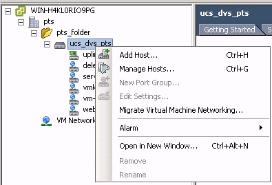
Add a Host to a vNetwork Distributed Switch
Use the Add Host to vNetwork Distributed Switch wizard in order to associate a host with a vNetwork Distributed Switch. You can also add hosts to a vNetwork Distributed Switch with the use of Host Profiles.Complete these steps:
Note: Enterprise plus license is a requirement for DVS.
-
In the vSphere Client, display the Networking inventory view and choose vNetwork Distributed Switch.
-
From the Inventory menu, choose Distributed Virtual Switch > Add Host. The Add Host to vNetwork Distributed Switch wizard appears.
-
Choose the host to add.
-
Under the selected host, choose the physical adapters to add, and click Next.You can choose both free and in use physical adapters. If you choose an adapter that is currently in use by a host, choose whether to move the associated virtual adapters to the vNetwork Distributed Switch.
Note: If you move a physical adapter to a vNetwork Distributed Switch without moving any associated virtual adapters, this causes those virtual adapters to lose network connectivity.
-
Click Finish.
Verify
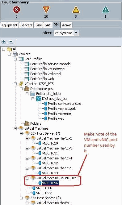
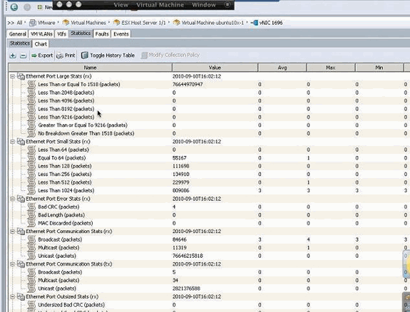
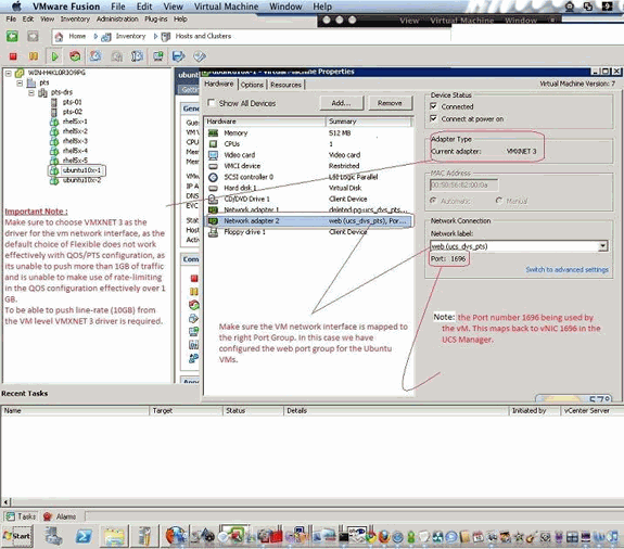
Once the VMs are added into VC and the correct Port Groups are mapped respectively, you see these from both the UCS Manager/VM tab and VC interfaces.
Testing QOS/Rate Limiting
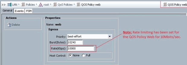
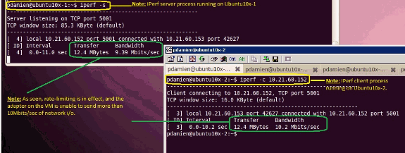
Test Case 1 - Qos Policy web - rate limited at 10Mbits/sec
On the QOS policy "web" rate limiting has been configured so the port group "web" is throttled at 10Mbits/sec.
Hosts running iPerf
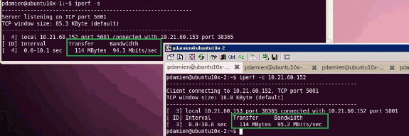
Test Case 2 - Qos Policy web - rate limited at 100Mbits/sec
On the QOS policy "web" rate limiting has been configured so the port group "web" is throttled at 100Mbits/sec.

Hosts running iPerf
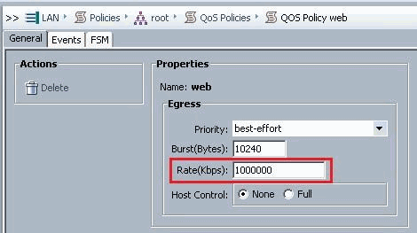
Test Case 3 - Qos Policy web - rate limited at 1000Mbits/sec
On the QOS policy "web" rate limiting has been configured so the port group "web" is throttled at 1000Mbits/sec.
Hosts running iPerf
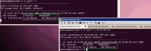
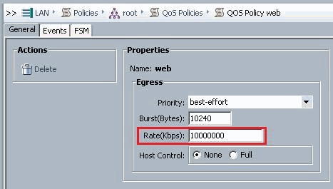
Test Case 4 - Qos Policy web - rate limited at 10000Mbits/sec
On the QOS policy "web" rate limiting has been configured so the port group "web" is throttled at 10000Mbits/sec.
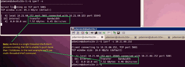
Hosts running iPerf
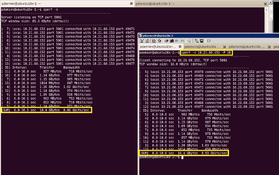
iPerf runs with 8 parallel threads and you can see the VM now able to push close to 10GB of network I/O.
Troubleshoot
There is currently no specific troubleshooting information available for this configuration.
Related Information
- Introduction to UCS M81KR Virtual Interface Card
- Overview of VN Link in Hardware
- Cisco UCS M81KR Virtual Interface Card
- Cisco UCS M81KR Virtual Interface Card Video Data Sheet
- UCS M81KR Whitepaper - Simplify and Enhance Your Virtual Environment
- UCS M81KR - Cisco VIC Performance with VMDirectPath
- Technical Support & Documentation - Cisco Systems
Revision History
| Revision | Publish Date | Comments |
|---|---|---|
1.0 |
21-Dec-2010 |
Initial Release |
Contact Cisco
- Open a Support Case

- (Requires a Cisco Service Contract)


 Feedback