Introduction
This document describes the difference between Hard- and Dynamic Pinning, Hard Pinning configuration for a Unified Computing System domain on IMM.
Prerequisites:
Requirements
Cisco recommends you have knowledge of these topics:
- Intersight Managed Mode
- Pin Groups
- Pinning: Dynamic Pinning & Static Pinning
- Fibre Channel
- Disjoint Layer 2
Components Used
The information in this document is based on these software and hardware versions
- Cisco UCS 6454 54-Port Fabric Interconnect in Ethernet and Fibre Channel End Host Mode
- Infrastructure bundle version: 4.2.1m
- Cisco UCS B200 M5 Server
- Server firmware version: 4.2.1a
The information in this document was created from the devices in a specific lab environment. All of the devices used in this document started with a cleared (default) configuration. If your network is live, ensure that you understand the potential impact of any command.
Background Information
Pinning is the process that Fabric Interconnect (FI) uses to establish the communication between servers and the network.
Virtual Network Interface Cards (vNICs) establish the connection to an uplink port or port channel available in the Fabric Interconnect. This process is known as Pinning.
Dynamic Pinning is the configuration that Fabrics Interconnect has as default.
Fabric Interconnect automatically binds server vNICs to uplink FI ports depending on the number of available uplinks configured.
Static pinning requires the administrator to use manual pin groups to bind vNICs to the uplink ports. FI does not do the configuration automatically.
Note: If the purpose is to disjoint the networks (separate VLANs in uplinks) the best approach for this is to configure Disjoint Layer 2, for reference see: Configure Disjoint Layer 2 in Intersight Managed Mode Domain
Topology
This configuration example in this document is based on the next topologies.
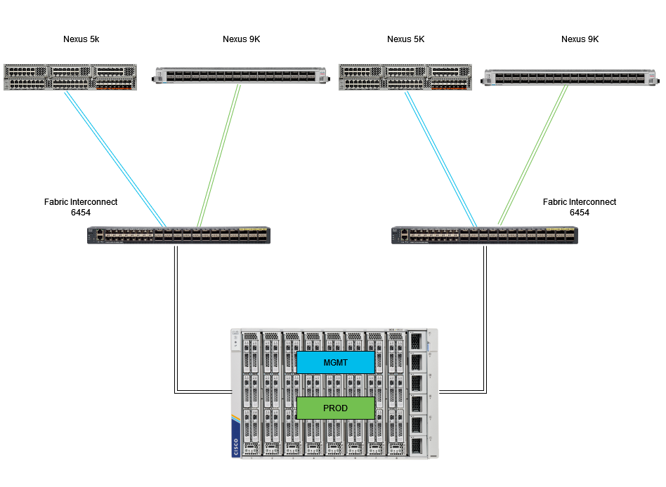 Eth pinnning topology
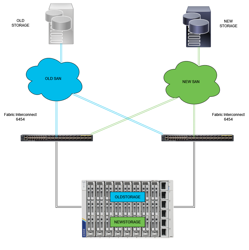 FC pinning topology
The configuration example for the Ethernet and Fibre Channel Pin Groups uses the same network (VLAN 1 and VSAN100).
The need for Pin Groups arises so traffic can be sent to different paths.
These topologies show situations and the possible use for Pin Groups in an environment.
Configure
Before you begin
Login to Intersight GUI as an administrator user.
Create Port Policy for UCS Domain
Configuration of Ethernet ports
Step 1. Locate on the Infrastructure Service tab. In the navigation plane, click on Configure Tab.
Step 2. On the Configure Tab, expand Configure > Policies.
Step 3. Click on Policies.
Step 4. Navigate to Create Policy and click on the button.
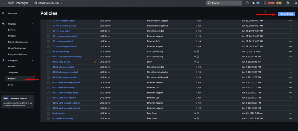 Create Policy
Step 5. On Platform Type, click on the UCS Domain option to filter policies and to find the Port policy easier. Select Port and click on Start.
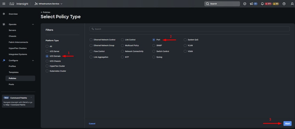 Port Policy
Step 6. Fill in the information required such as Organization, Name, and Switch Model. Those are mandatory.
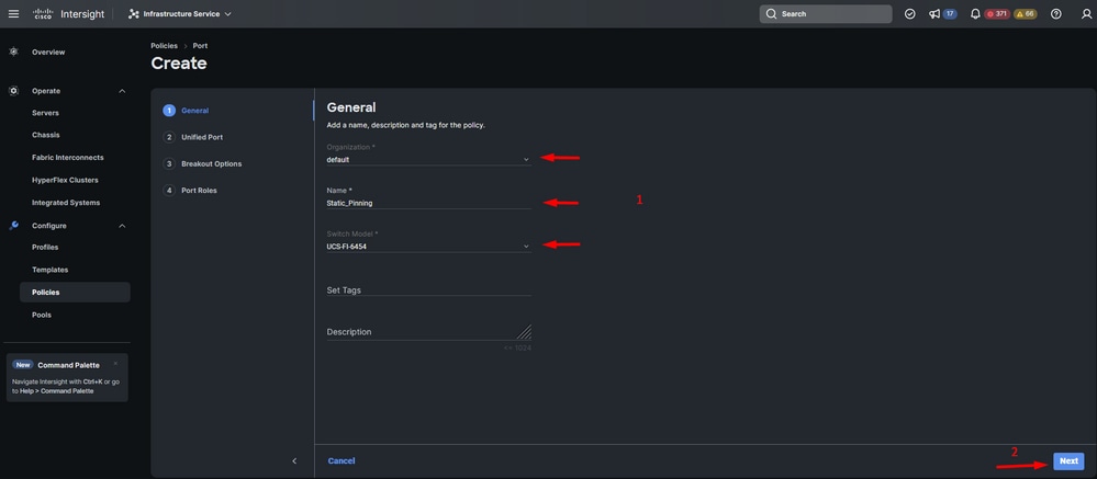 Organization, Name & Switch model information
Caution: Configuring Unified ports requires fabric interconnect to reboot.
Step 7. Configure your Fibre Channel uplink ports and breakouts as needed.
Step 8. Configure unified ports to the number of Fibre Channel ports. For this sample configuration, the number of FC ports would be 4. Verify the number of FC and Ethernet ports. Click Next.
Note: The maximum number is FC ports for Fabric Interconnect 6454 is 16.
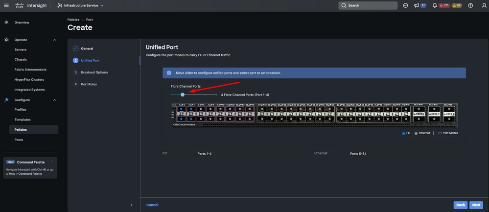 Unified port
For this sample configuration, Breakout ports are not required. If needed, on Breakout Options set the number of ports and modify the speed as desired.
Step 9. On port roles, complete the next actions to configure server ports:
- Select ports and click on Configure. It takes you to a new window where you display a menu to select the desired type of role for the selected ports have.
For this sample configuration, port 33 is used as a server port.
Tip: This configuration example only shows the Ethernet Uplink configuration and FC Uplinks configuration. Other port roles can be configured in this step as well.
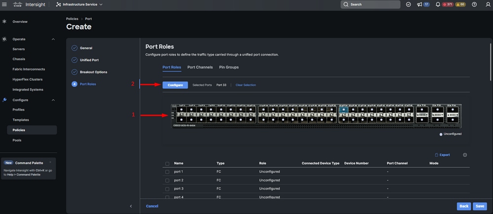 Server port configuration
- Select Server as the role. Leave FEC as Auto and Manual Chassis/Server Numbering as it is.
- Click Save.
Note: Chassis and Rack Servers are numbered automatically as discovered.
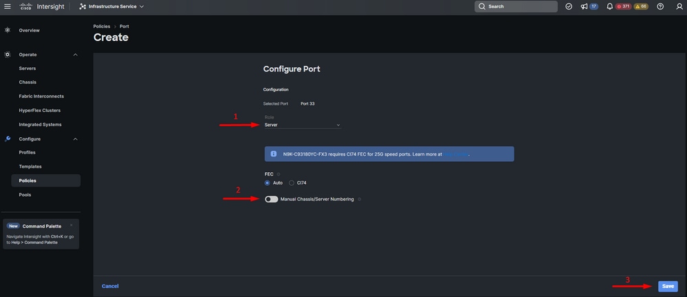 Server port
Step 10. Repeat the procedure from step 9 to configure uplink ports.
For this sample configuration, ports 53 and 54 are the uplink ports.
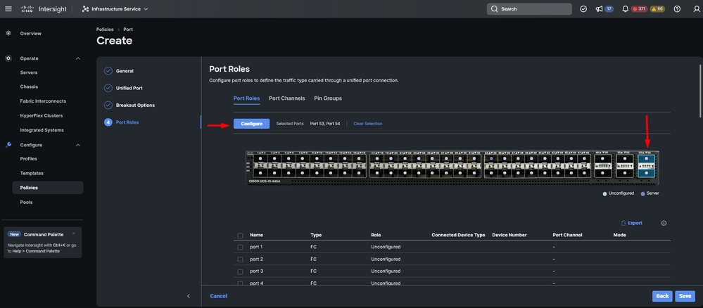 Uplinks ports configuration
- Leave Admin Speed as Auto if you do not need a specific one. Same for FEC.
- Select or create a policy for ethernet network group, flow control, and link control depending on the requirements of your environment. Click on Select Policy for each policy and modify it as desired.
- Verify your configuration. Click on Save.
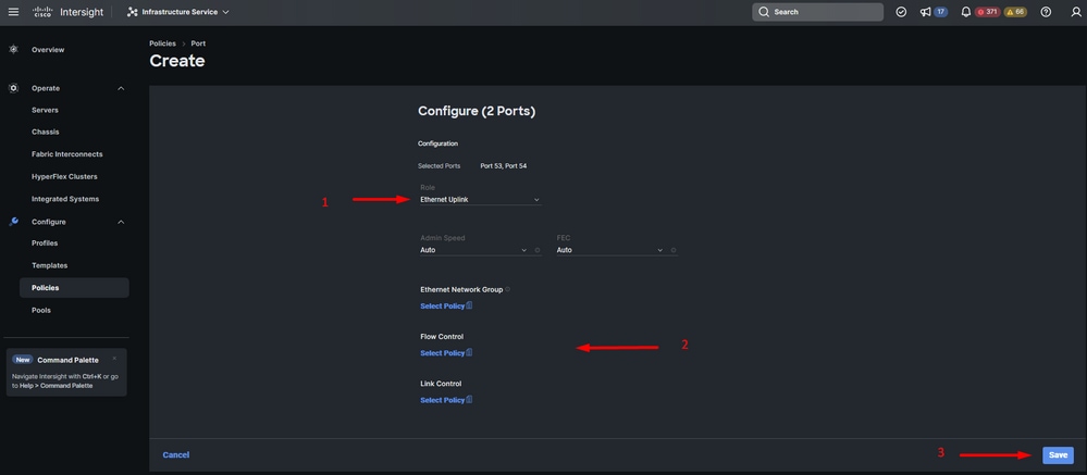 Ethernet Uplinks
Step 11. Navigate to Pin Groups. Then click on Create Pin Group.
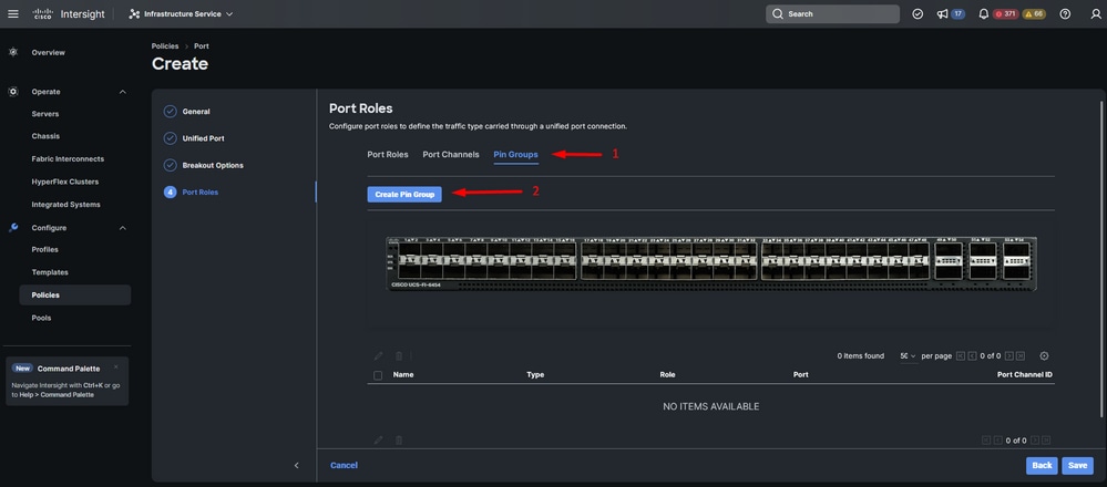 Pin Group for Ethernet uplinks
Complete the next actions to configure Pin Groups:
- Select Pin Group Type. As it is an ethernet uplink, select the LAN option.
- Name your Pin Group with a particular name you can recognize in the future. This example uses EthMGMT.
- Interface Type depends on the needs of the environment.
For this sample configuration, it is set as Port. Use Port Channel if your environment requires it.
- Select the desired ethernet uplink for this Pin Group.
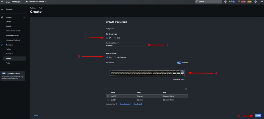 Pin Group for Management
- Repeat the procedure for the uplink. For this sample configuration, the second uplink is named EthPROD.
- Click Save.
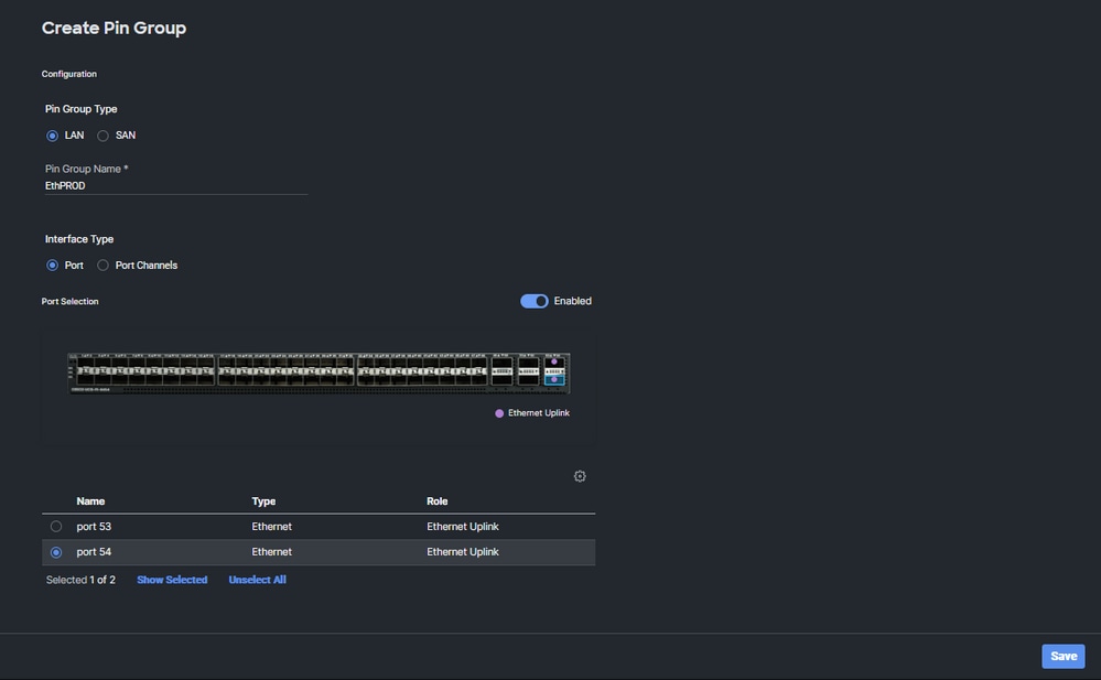 Ethernet uplink for production
- Verify your configuration. See your Pin Groups created on the Pin Group tab. Click Save.
Configuration of Fibre Channel ports
Step 1. Complete the next actions to configure Fibre Channel ports.
- Navigate to the Port Roles tab. Select the desired FC ports to use, and right-click Configure.
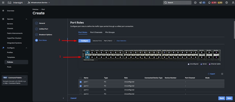
- Select a role for this FC port, set the speed, and type the VSANID that is associated with these ports.
- Click on Save.
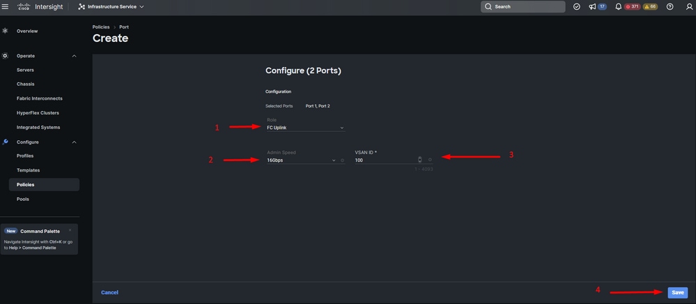 Fiber channel uplink configuration
Step 2. Create Pin Group for FC uplinks. The procedure is similar to the configuration of Ethernet ports.
- Select SAN as Pin Group Type. Name the Pin Group with a reference for its use. OldStorage exemplifies what it is used for.
- Interface Type depends on the needs of the environment.
- Select the desired FC uplink for this Pin Group.
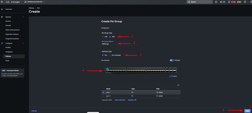 Old Storage FC uplink
- Repeat the procedure for the other FC uplink. NewStorage is the name for this Pin Group for this sample configuration.
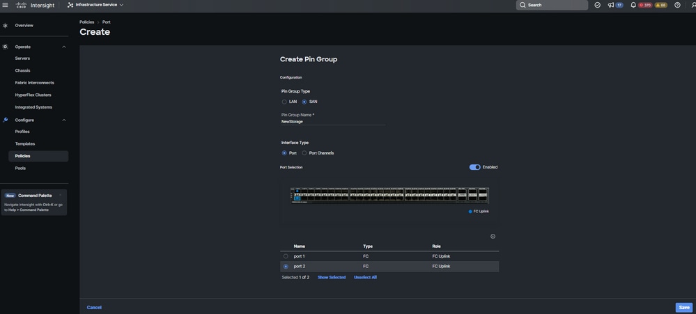 New Storage FC uplink
- Verify the Pin Groups created configuration.
- Click on Save once completed.
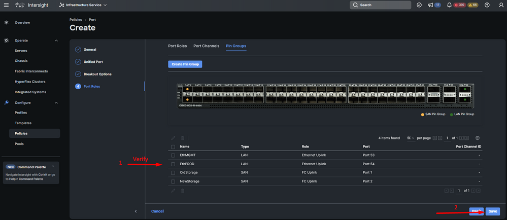 Verify Pin Groups
Create LAN Connectivity Policy for UCS Server.
Step 1. Navigate to Create Policy and click on the button. On Platform Type, click on the UCS Server option to filter policies and to find the LAN Connectivity policy easier. Select it and click on Start.
Step 2. Select Organization, name your policy, and choose the target platform for which the server profile is applicable. Click Next.
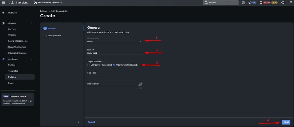 General information for LAN policy
Step 3. Navigate to vNIC Configuration and click on Add vNIC button.
Step 4. Name your vNIC and select the Pin Group name associated with this vNIC for static pinning.
Step 5. Select or create a Pool Policy for Mac addresses about to utilize. You can choose the Static option if you need a specific one.
Step 6. Select carefully the switch ID this vNIC is going to belong to.
For this sample configuration, MGMT_A belongs to the EthMGMT pin group and it points to Fabric Interconnect A.
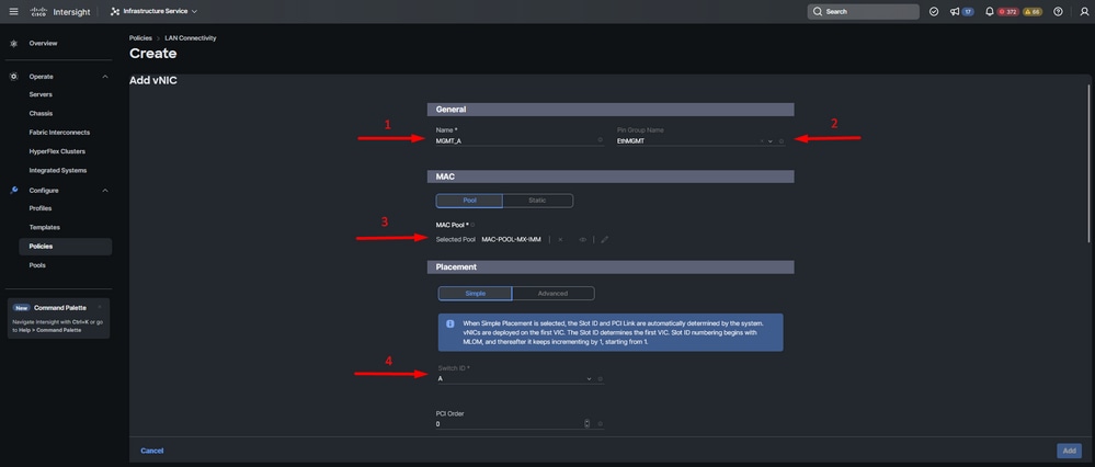 vNIC configuration
Step 7. Enable Failover and select a policy for each marked (*) policy. Four of them need one policy selected to be able to Add your vNIC.
Step 8. Click Add once completed.
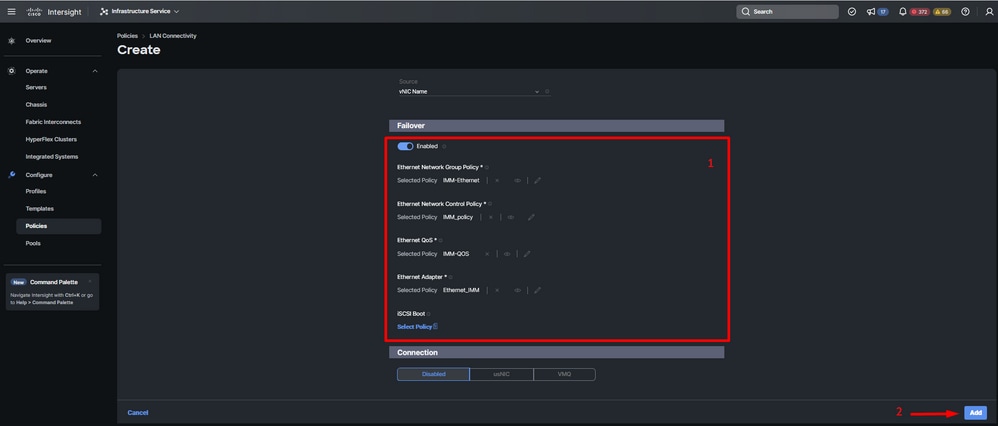 Fialover and policies for vNIC configuration
Step 9. Repeat the procedure since step 3 for the other vNICs. Then Verify all are properly configured.
Step 10. Click on Create.
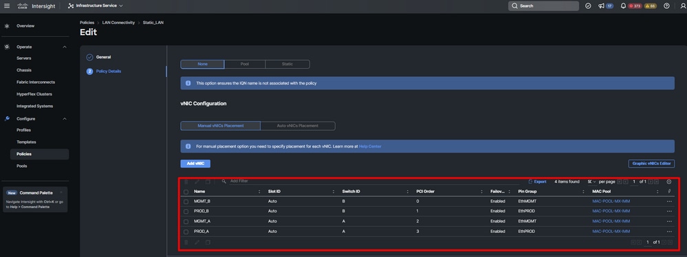 LAN policy Verification
Create SAN Connectivity Policy for UCS Server.
Step 1. Navigate to Create Policy and click on the button. On Platform Type, click on the UCS Server option to filter policies and to find the SAN Connectivity policy easier. Select it and click on Start.
Step 2. Select Organization, name your policy, and choose the target platform for which the server profile is applicable. Click Next.
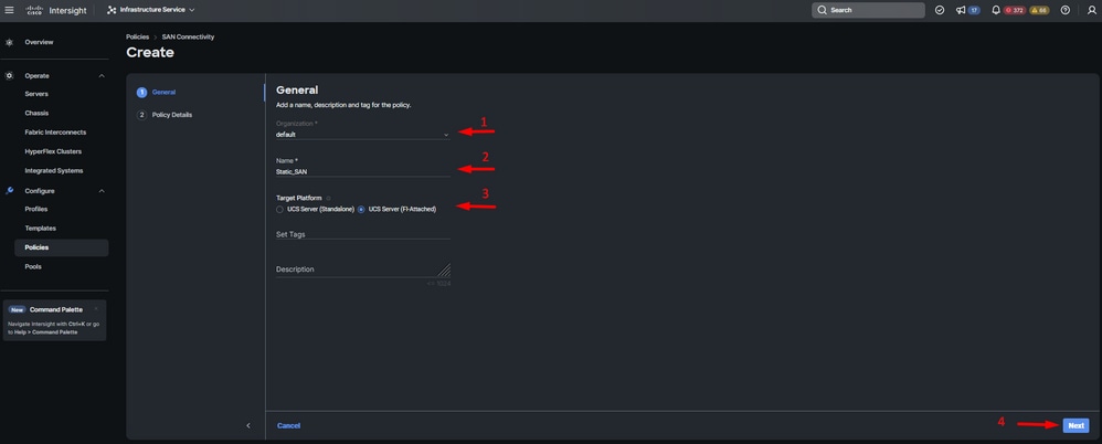 General Information SAN policy
Step 3. Select Manual vHBAs Placement.
Step 4. Navigate to WWNN and select or create WWNN Pool.
Step 5. Click on Add vHBA button.
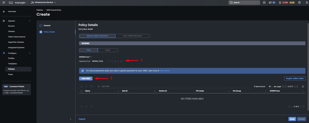 SAN policy
Step 6. Name your vHBA and select the Pin Group name associated with this vHBA for static pinning. Choose fc-initiator as vHBA Type.
Step 7. Select or create a Pool Policy for WWPN to utilize. You can choose the Static option if you need a specific one.
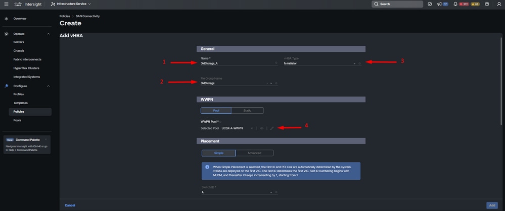 vHBA configuration policy
Step 8. Navigate to Placement. Select carefully the switch ID this vHBA is going to belong to.
For this sample configuration, OldStorage_A belongs to the OldStorage pin group and it points to Fabric Interconnect A.
Tip: Enable Persistent LUN Bindings if you need retention of LUN ID associations in memory. This persists until you manually clear them.
Step 9. Select a policy for each marked (*) policy. Three of them need one policy selected to be able to Add your vHBA.
Step 10. Click Add once completed.
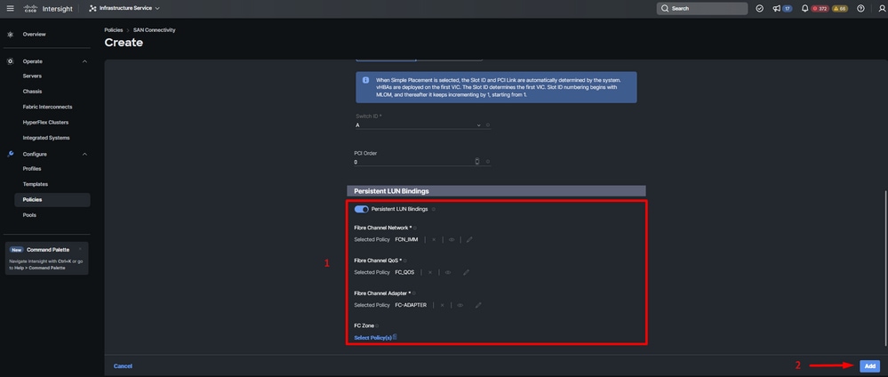 vHBA configuration policy
Step 11. Repeat the procedure from step 3 for the other vNICs. Then Verify all are properly configured.
Step 12. Click Create.
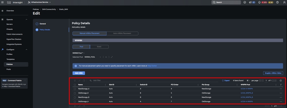 Verification SAN policy
Caution: Verify numbers on the PCI Order are not repeated. The adapter cannot have the same PCI order for vNICs or vHBAs.
Verify
Associate the Port policy to your UCS Domain and then LAN & SAN policies to your Service Profile.
To verify the configuration with the command show pinning server-interfaces from the command line if your Fabric Interconnect.
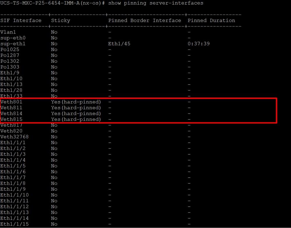 Hard pinning
There is no command that explicitly shows hard pinning is enabled as Ethernet does.
However, you can type show npv traffic-map command to verify the uplink configured o your policy.
This command works when the Fabric Interconnect is in End Host Mode. Otherwise, the command is not available.
 FC uplink verification
Related Information


 Feedback