Manage Platform Settings on the FindIT Network Probe
Available Languages
Objective
The Cisco FindIT Network Management provides tools that help you easily monitor, manage, and configure your Cisco 100 to 500 Series network devices such as switches, routers, and wireless access points (WAPs) by using your web browser. It also notifies you about device and Cisco Support notifications such as the availability of new firmware, device status, network settings updates, and any connected devices that are no longer under warranty or covered by a support contract.
The FindIT Network Management is a distributed application which is comprised of two separate components or interfaces: one or more Probes referred to as FindIT Network Probe and a single Manager called FindIT Network Manager.
The platform settings contain the basic system settings that are required by Probe in order to function. Some settings include the IP address of the Administrative GUI, hostname, and time settings. These settings are typically configured upon the installation of Cisco FindIT Manager and Probe. If an administrator decides to change any of the settings after the installation, instead of going through the Command Line Interface (CLI), one can go through the Administrative GUI.
This document aims to show you how to configure and manage platform settings through the Administrative GUI.
Configure Platform Settings
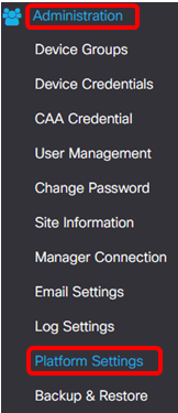
Step 1. Log in to the FindIT Network Probe and choose Administration > Platform Settings.
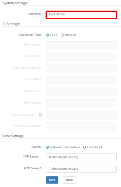
Step 2. In the Hostname field, enter a hostname for the Probe. The field may already be filled with a name created during the installation process of FindIT Probe. This hostname is the identity used by Bonjour to identify the instance of FindIT Probe on the network.
Note: For this example, FindITProbe is used as the hostname.
IP Settings
Step 3. For the IP Settings, choose a radio button to determine the method on how the FindIT Probe will obtain an IP address. The options are:
- DHCP — A Dynamic Host Configuration Protocol (DHCP) server automatically assigns an IP address for the Administrative GUI. This is the default. If you chose this, skip to Step 12.
- Static IP — Manually assign an IP address for the Administrative GUI.
Note: In this example, Static IP is chosen.
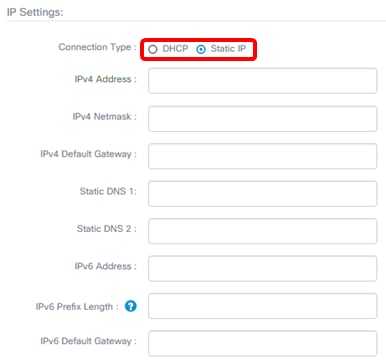
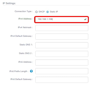
Step 4. In the IPv4 Address field, assign a local IP address to the Probe Administrative GUI following the IPv4 format.
Note: In this example, 192.168.1.108 is used.
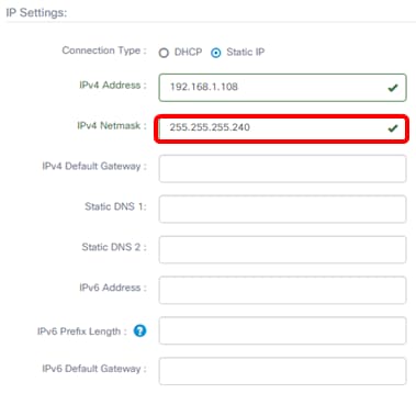
Step 5. In the IPv4 Netmask field, enter a subnet mask address.
Note: For this example, 255.255.255.240 is used.
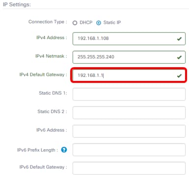
Step 6. In the IPv4 Default Gateway, enter the IPv4 default gateway of the router.
Note: For this example, 192.168.1.1 is used.
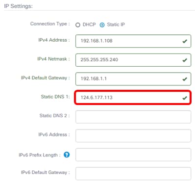
Step 7. In the Static DNS 1 field, enter the DNS address.
Note: In this example. 124.6.177.113 is used.
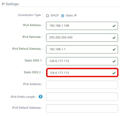
Step 8. (Optional) Enter a secondary DNS server address in the Static DNS 2 field.
Note: In this example, 124.6.177.112 is used.
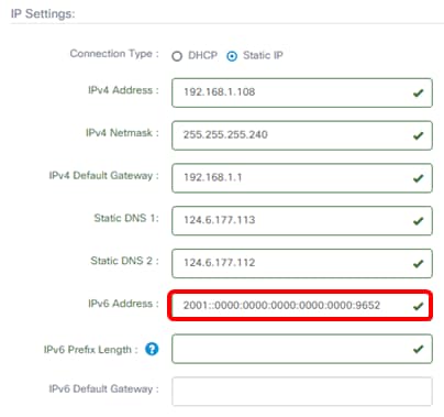
Step 9. (Optional) Assign an IPv6 address in the IPv6 Address field.
Note: In this example, 2001::0000:0000:0000:0000:9652 is used.
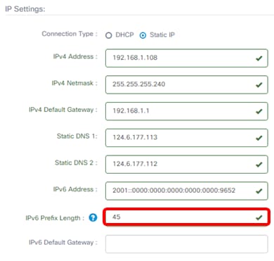
Step 10. (Optional) In the IPv6 Prefix Length field, enter the IPv6 prefix length according to your IP addressing scheme.
Note: In this example, 45 is used.
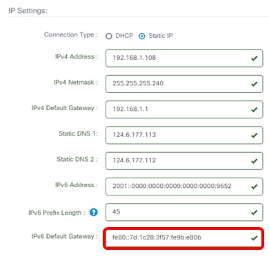
Step 11. (Optional) Enter the IPv6 default gateway in the IPv6 Default Gateway field.
Note: In this example, fe80::7d:1c28:3f57:fe9b:e80b is used.
Time Settings
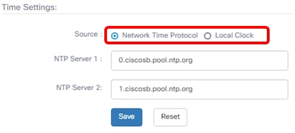
Step 12. In the Source area, click a radio button to set how the Probe will synchronize its clock. The options are:
- Network Time Protocol — Specify the preferred NTP servers for the Probe to use. This is the default.
- Local Clock — Click this if you want the Probe to synchronize with a public NTP server. If you clicked this, skip to Step 15.
Note: In this example, Network Time Protocol is used.
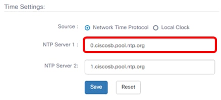
Step 13. In the NTP Server 1 field, enter the primary NTP server address to synchronize with the Probe.
Note: For this example, 0.ciscosb.pool.ntp.org is used.
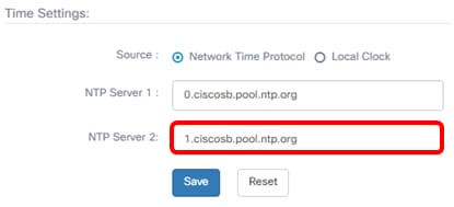
Step 14. Enter a secondary NTP server address in the NTP Server 2 field. This serves as a backup in case the primary NTP server address fails to synchronize with the Probe.
Note: For this example, 1.ciscosb.pool.ntp.org is used.
Step 15. Click Save.
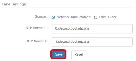
You should now have successfully configured or managed the platform settings.
Contact Cisco
- Open a Support Case

- (Requires a Cisco Service Contract)
 Feedback