Configuring Site-to-Site VPN on the RV34x
Available Languages
Objective
The objective of this document is to create a site-to-site VPN on RV34x Series Routers.
Introduction
A virtual private network (VPN) is a great way to connect remote workers to a secured network. A VPN allows a remote host to act as if they were connected to the onsite secured network. In a site-to-site VPN, the local router at one location connects to a remote router through a VPN tunnel. This tunnel encapsulates data securely by using industry-standard encryption and authentication techniques to secure data that is sent.
Configuration of a site-to-site VPN involves setting the IPsec profile and the configuration of the site-to-site VPN on the two routers. The IPsec profile is already configured to make it easy to set up site-to-site VPN, even with a 3rd party (such as AWS or Azure). The IPsec profile contains all the necessary encryption for the tunnel. Site-to-site VPN is the configuration so the router knows which other site to connect to. If you choose not to use the preconfigured IPsec profile, you have the option to create a different one.
When you are configuring site-to-site VPN, the Local Area Network (LAN) subnets on either side of the tunnel cannot be on the same network. For example, if the Site A LAN uses the 192.168.1.x/24 subnet, Site B cannot use the same subnet. Site B has to use a different subnet, such as 192.168.2.x/24.
To configure a tunnel properly, enter corresponding settings (reversing local and remote) when configuring the two routers. Assume that this router is identified as Router A. Enter its settings in the Local Group Setup section while entering the settings for the other router (Router B) in the Remote Group Setup section. When you configure the other router (Router B), enter its settings in the Local Group Setup section, and enter the Router A settings in the Remote Group Setup.
Below is a table of the configuration for both Router A and Router B. Highlighted in bold are parameters that are the inverse of the opposite router. All other parameters are configured the same. In this document we will be configuring the local router, Router A.
| Field |
Local Router (Router A)
WAN IP address: 140.x.x.x Private IP address (local): 192.168.2.0/24 |
Remote Router (Router B)
WAN IP address: 145.x.x.x Private IP address (local): 10.1.1.0/24 |
| Connection Name | VPNTest | VPNTestRemote |
| IPsec Profile | TestProfile | TestProfile |
| Interface | WAN1 | WAN1 |
| Remote Endpoint | Static IP | Static IP |
| Remote Endpoint IP address | 145.x.x.x | 140.x.x.x |
| Pre-shared Key | CiscoTest123! | CiscoTest123! |
| Local Identifier Type | Local WAN IP | Local WAN IP |
| Local Identifier | 140.x.x.x | 145.x.x.x |
| Local IP Type | Subnet | Subnet |
| Local IP address | 192.168.2.0 | 10.1.1.0 |
| Local Subnet Mask | 255.255.255.0 | 255.255.255.0 |
| Remote Identifier Type | Remote WAN IP | Remote WAN IP |
| Remote Identifier | 145.x.x.x | 140.x.x.x |
| Remote IP Type | Subnet | Subnet |
| Remote IP address | 10.1.1.0 | 192.168.2.0 |
| Remote Subnet Mask | 255.255.255.0 | 255.255.255.0 |
Applicable Devices
· RV34x
Software Version
· 1.0.02.16
Configuring Site-to-Site VPN Connection
Step 1. Log into the web configuration page of your router.

Step 2. Navigate to VPN > Site-to-Site.

Step 3. Click the add button to add a new Site-to-Site VPN connection.

Step 4. Check Enable to enable the configuration. This is enabled by default.

Step 5. Enter a connection name for the VPN tunnel. This description is for reference purposes and does not have to match the name used at the other end of the tunnel.
In this example, we will be entering VPNTest as our connection name.

Step 6. Select the IPsec profile that you want to use for the VPN. IPsec profile is the central configuration in IPsec that defines the algorithms such as encryption, authentication, and Diffie-Hellman (DH) group for Phase I and Phase II negotiation.
To learn how to configure IPsec profile using IKEv2, please click the link: Configuring IPsec Profile using IKEv2 on the RV34x.
Note: The option of using a 3rd party (Amazon Web Services or Microsoft Azure) for IPsec profile is available. This IPsec profile is already configured with all the necessary selections that needs to be configured for Amazon Web Services or Microsoft Azure so you don’t have to configure it. If you are trying to configure site-to-site VPN between AWS or Azure to your site, then you would need to use the information that AWS or Azure gives you on their side and use the preconfigured IPsec profile when configuring site-to-site VPN on this side.
For this example, we will be selecting TestProfile as our IPsec profile.

Step 7. In the Interface field, select the interface used for the tunnel. In this example, we will be using WAN1 as our interface.

Step 8. Select either Static IP, Fully Qualified Domain Name (FQDN), or Dynamic IP for the Remote Endpoint. Enter in the IP address or FQDN of the remote endpoint based on your selection.
We have selected Static IP and entered in our remote endpoint IP address.

Configuring IKE Authentication Method
Step 1. Select either Pre-shared Key or Certificate.
Pre-shared Key: IKE peers authenticate each other by computing and sending a keyed hash of data that includes the pre-shared key. Both peers must share the same secret key. If the receiving peer is able to create the same hash independently using its pre-shared key, it authenticates the other peer. Pre-shared keys do not scale well because each IPsec peer must be configured with the pre-shared key of every other peer with which it establishes a session.
Certificate: The digital certificate is a package that contains information such as a certificate bearer’s identity including a name or IP address, the certificate’s serial number, the certificate’s expiration date, and a copy of certificate bearer’s public key. The standard digital certificate format is defined in the X.509 specification. X.509 version 3 defines the data structure for certificates. If you have selected Certificate, make sure your signed certificate is imported in Administration > Certificate. Select the certificate from the drop-down list for both local and remote.
For this demonstration, we will be selecting Pre-shared key as our IKE authentication method.
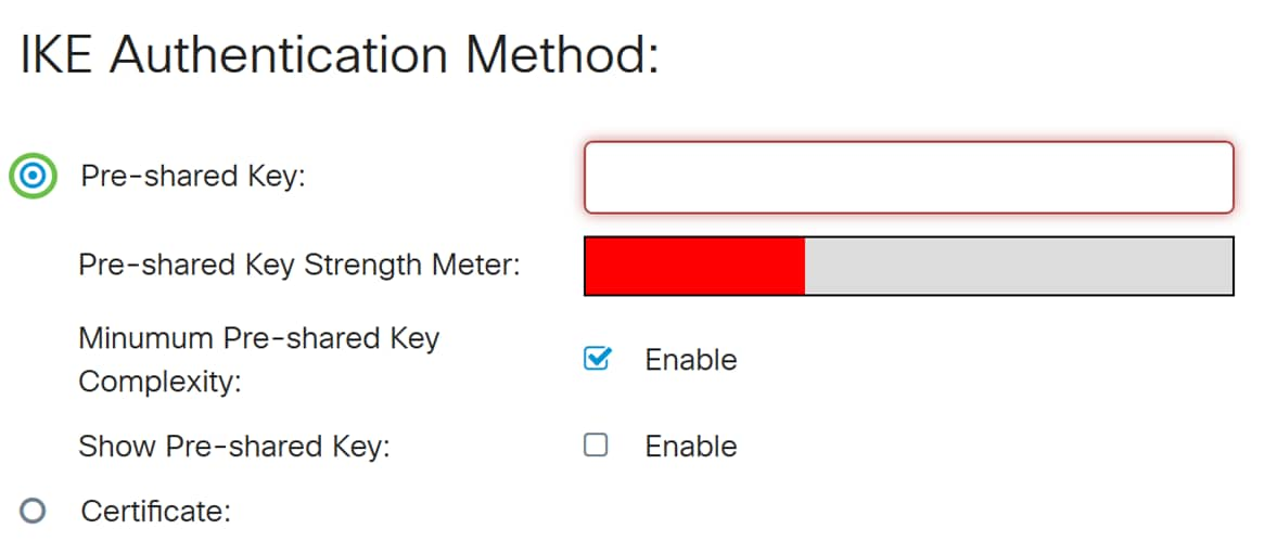
Step 2. In the Pre-shared Key field, enter in a pre-shared key.
Note: Make sure the remote router uses the same pre-shared key.
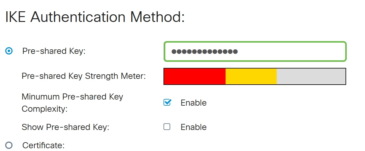
Step 3. The Pre-shared Key Strength Meter shows the strength of the pre-shared key through colored bars. Check Enable to enable the minimum pre-shared key complexity. The pre-shared key complexity is checked by default. If you would like to display the pre-shared key, check the Enable checkbox.

Local Group Setup
Step 1. Select Local WAN IP, IP Address, Local FQDN, or Local User FQDN from the drop-down list. Enter the identifier name or IP Address based on your selection. If you have selected Local WAN IP, the WAN IP address of your router should automatically be entered.
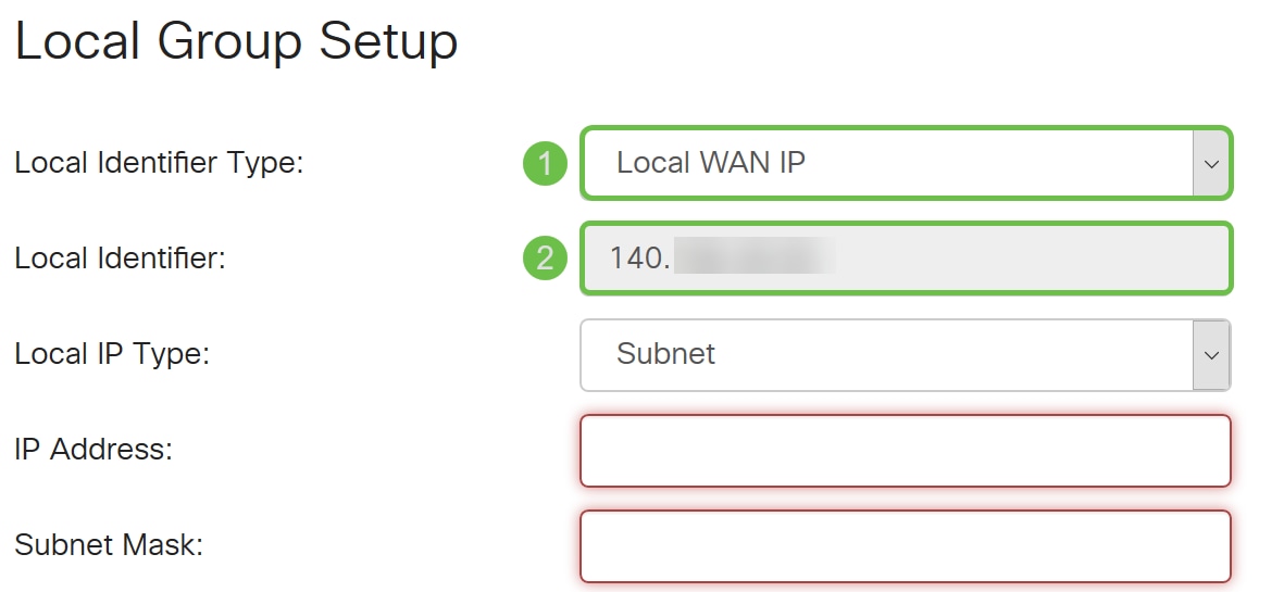
Step 2. For the Local IP Type, Select Subnet, Single, Any, IP Group, or GRE Interface from the drop-down list.
In this example, Subnet was chosen.
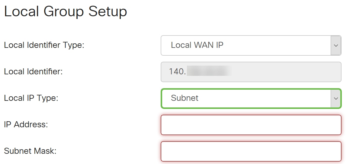
Step 3. Enter the IP address of the device that can use this tunnel. Then enter the subnet mask.
For this demonstration, we will be entering 192.168.2.0 as our local IP address and 255.255.255.0 for the subnet mask.

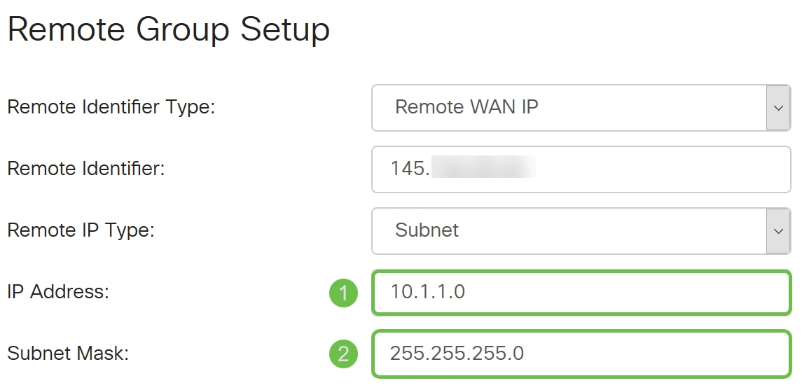
Remote Group Setup
Step 1. Select Remote WAN IP, Remote FQDN, or Remote User FQDN from the drop-down list. Enter the identifier name or IP Address based on your selection.
We have selected Remote WAN IP as our Remote Identifier Type and entered in the IP address of the remote router.

Step 2. Select Subnet, Single, Any, IP Group from the Remote IP Type drop-down list.
In this example, we will be selecting Subnet.
Note: If you have selected IP Group as your remote IP type, a popup window to create a new IP group will appear.
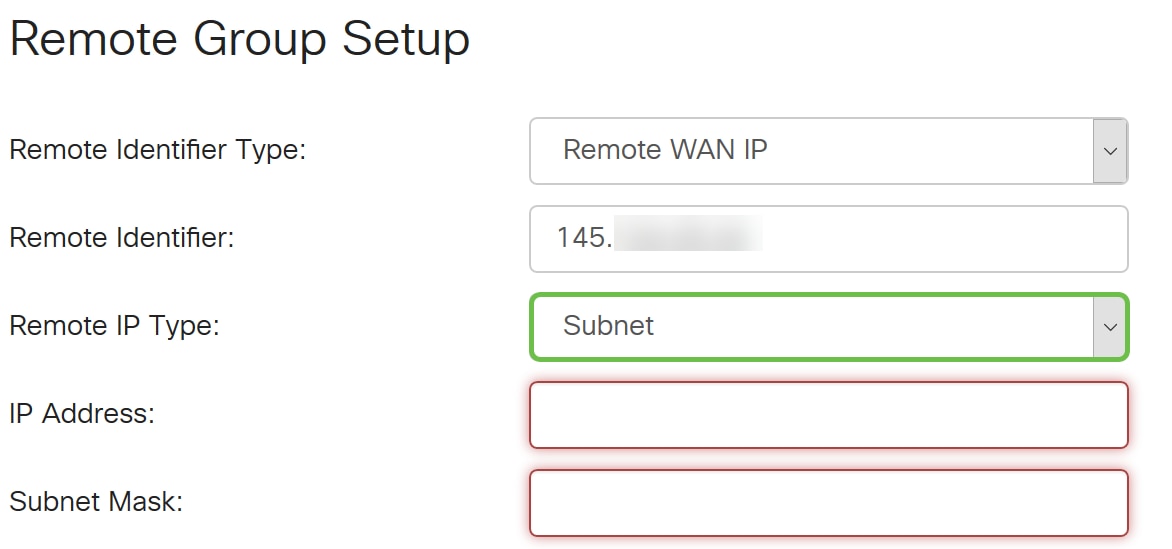
Step 3. Enter the IP address and subnet mask of the device that can use this tunnel.
We have entered 10.1.1.0 for the remote local IP address that can use this tunnel and the subnet mask of 255.255.255.0.
Step 4. Click Apply to create a new Site-to-Site VPN connection.

All configurations that you have entered on the router are in the Running Configuration file which is volatile and is not retained between reboots.
Step 5. At the top of the page, click the Save button to navigate to the Configuration Management to save your running configuration to the startup configuration. This is to retain the configuration after a reboot.

Step 6. In the Configuration Management, make sure the Source is Running Configuration and the Destination is Startup Configuration. Then press Apply to save your running configuration to the startup configuration. The Startup Configuration file will now retain all configurations after a reboot.

Conclusion
You should now have successfully added a new Site-to-Site VPN connection for your local router. You would need to configure your remote router (Router B) using the reverse information.
 Feedback