Troubleshoot of Access Lists over Virtual Private Network on RV016, RV042, RV042G and RV082 VPN Routers
Available Languages
Objectives
An Access Control List (ACL) is a collection of permit and deny conditions. An ACL specifies which user or system processes are granted access to specific resources. An ACL can block any unwarranted attempts to reach network resources. The problem in this situation can arise when you have ACLs configured on both the routers but one of the routers cannot differentiate between the allowed and denied lists of traffic permitted by the ACL. Zenmap which is an open source tool used for checking the type of packet filters/firewalls active is used to test the configuration.
This article explains how to troubleshoot the allowed ACLs which do not work over gateway-to-gateway VPN between two VPN Routers.
Applicable Devices
• RV016
• RV042
• RV042G
• RV082
Software Version
• v4.2.2.08
ACL over VPN Configuration
Step 1. Log in to the web configuration utility and choose Firewall > Access Rules. The Access rule page opens:
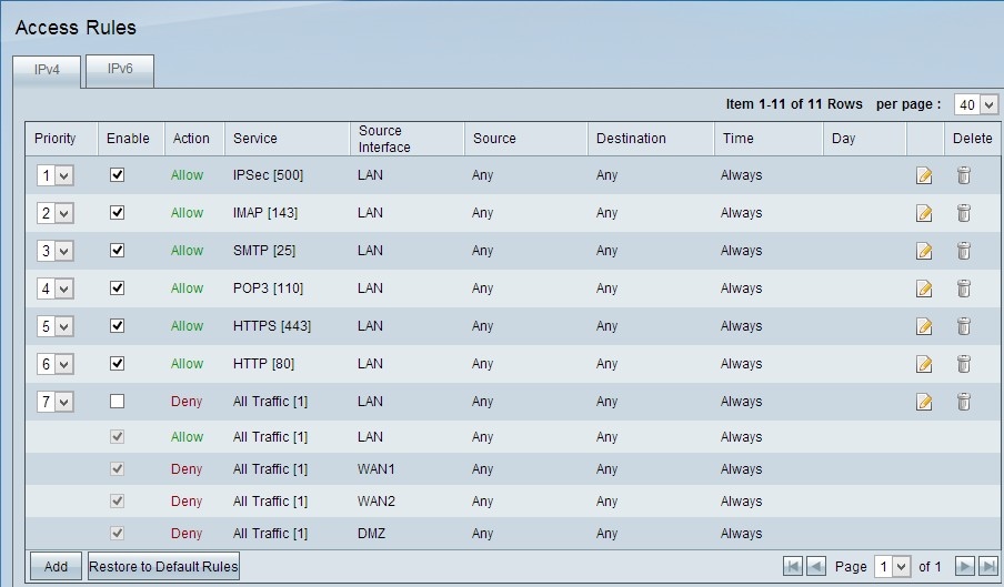
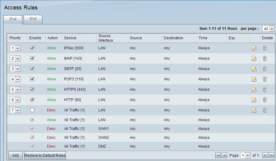
Note: The default access rules cannot be edited. The access rules mentioned in the image above which are user configured can be edited by the following process.
Step 2. Click the Add button to add a new access rule. The Access Rules page changes to show the Services and the Scheduling areas. Addition of one access rule is explained in the following steps.
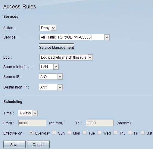
Step 3. Choose Deny from the Action drop-down list to deny the service.

Step 4. Choose the required service that is applied to the rule from the Service drop-down list.
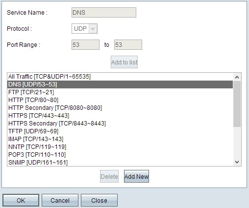
Step 5. (Optional) To add a service that is not present in the service drop-down list, click Service Management. In Service Management, a service can be created as needed. After a service is created, click OK to save Settings.
Step 6. Choose Log packets that match this rule from the Log drop-down list for only logs that match or Not Log for logs that do not match the access rule.
Step 7. Choose an interface type from the Source Interface drop-down list which is the source for the access rules. The available options are:
• LAN — Choose LAN if the source interface is the Local Area Network.
• WAN — Choose WAN if the source interface is the ISP.
• DMZ — Choose DMZ if the source interface is the Demilitarized zone.
• ANY — Choose ANY to make the source interface as any of the above mentioned interfaces.
Step 8. From the Source IP drop-down list, choose the desired source address(es) that applies to the access rule. The available options are:
• Single — Choose Single if it is a single IP address and enter the IP address.
• Range — Choose Range if it is a range of IP addresses and enter the first and last IP address in the range.
• ANY — Choose ANY to apply the rules to all the Source IP addresses.
Step 9. From the Destination IP drop-down list, choose the desired destination address(es) that applies to the access rule. The available options are:
• Single — Choose Single if it is a single IP address and enter the IP address.
• Range — Choose Range if it is a range of IP address and enter the first and last IP address in the range.
• ANY — Choose ANY to apply the rules to all the Destination IP addresses.
Step 10. Choose a method to define when the rules are active from the Time drop-down list. They are:
• Always — If you choose Always from the Time drop down list, the access rules will always be applied to traffic.
• Interval — You can choose a specific time interval at which the access rules are active if you select Interval from the Time drop down list. After you specify the time interval, check the check boxes of the days when you want the access rules to be active from the Effective On field.
Step 11. Click Save to save your settings.
Step 12. Repeat steps 2 to 10 with the fields matching to that shown in the image respectively. Access rules as per customer are applied here. The first 7 are allowing some services; the 8th denies all other traffic. This configuration is made on the second router as well. IPSec Port 500 is allowed.
Note: Do this for both the routers to verify that access rules are configured as desired.
VPN Router # 1
VPN Router # 2
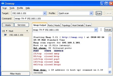
Step 13. Install Zenmap(NMAP) from http://nmap.org/download.html the and Launch it on a PC in the 192.168.2.0 LAN.
Note: This is the LAN behind the router with the seven additional ACLs. The target IP (192.168.1.101) is a PC on the Remote Gateway LAN.
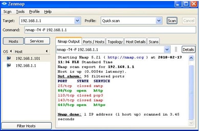
Step 14. Select Quick Scan from the profile and click on Scan. Through this we can know the ports opened and filtered as per the ACL's, the result shown is represented in the image above. Output shows that these ports are closed, regardless of the allowed ACLs being configured on the RV0xx # 1. If we try to check the ports to the LAN IP (192.168.1.1) of the remote gateway – we discover that ports 80 and 443 are open (which were closed to the PC 192.168.1.101).
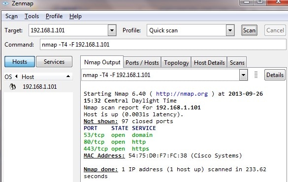
The ACL performs correctly after the removal of 7th denied ACL and works fine as we can see from the output.
Revision History
| Revision | Publish Date | Comments |
|---|---|---|
1.0 |
11-Dec-2018 |
Initial Release |
 Feedback