Add and Configure Access Rules on RV130 and RV130W
Available Languages
Objective
Network devices provide basic traffic filtering capabilities with access rules. An access rule is a single entry in an Access Control List (ACL) that specifies a permit or deny rule (to forward or drop a packet) based on the protocol, a source and destination IP address, or network configuration.
The objective of this document is to show you how to add and configure an Access Rule on the RV130 and RV130W.
Applicable Devices
• RV130
• RV130W
Software Versions
• Version 1.0.1.3
Add and Configure an Access Rule
Setting Default Outbound Policy
Step 1. Log in to the web configuration utility and choose Firewall > Access Rules. The Access Rules page opens:

Step 2. In the Default Outbound Policy area, click the desired radio button to choose a policy for outbound traffic. The policy is applied whenever there are no access rules or Internet access policies configured. The default setting is Allow, which allows all traffic to the Internet to pass through.

The available options are defined as follows:
• Allow — Permit all types of traffic going out from the LAN to the Internet.
• Deny — Block all types of traffic going out from the LAN to the Internet.
Step 3. Click Save to save the settings.

Adding an Access Rule
Step 1. Log in to the web configuration utility and choose Firewall > Access Rules. The Access Rules window opens:

Step 2. Click Add Row in the Access Rule Table to add a new access rule.

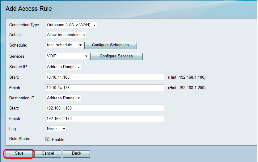
The Add Access Rule page opens:
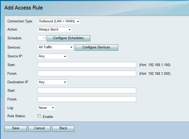
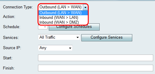
The available options are defined as follows:
• Outbound (LAN > WAN) — The rule affects packets that come from the local network (LAN) and go out to the Internet (WAN).
• Inbound (WAN > LAN) — The rule affects packets that come from the Internet (WAN) and go into the local network (LAN).
• Inbound (WAN > DMZ) — The rule affects packets that come from the Internet (WAN) and go into the demilitarized zone (DMZ) subnetwork.
Step 4. From the Action drop-down list, choose the action to be taken when a rule is matched.
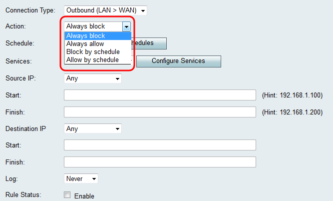
The available options are defined as follows:
• Always Block — Always deny access if the conditions are matched. Skip to Step 6.
• Always Allow — Always permit access if the conditions are matched. Skip to Step 6.
• Block by schedule — Deny access if the conditions are matched during a preconfigured schedule.
• Allow by schedule — Permit access if the conditions are matched during a preconfigured schedule.
Step 5. If you chose Block by schedule or Allow by schedule in Step 4, choose the appropriate schedule from the Schedule dropdown list.
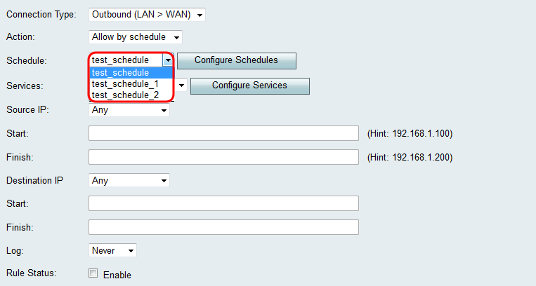
Note: To create or edit a schedule, click Configure Schedules. Refer to Configuring Schedules on the RV130 and RV130W for more information and guidelines.
Step 6. Choose the type of service the access rule applies for from the Services drop-down list.
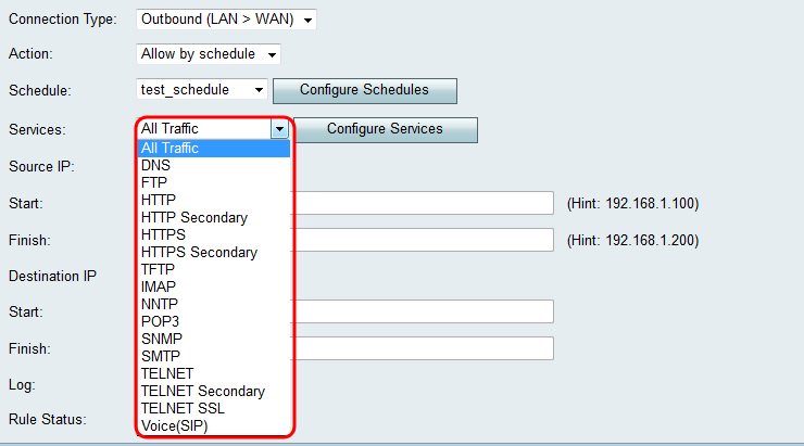
Note: If you want to add or edit a service, click Configure Services. Refer to Service Management Configuration on the RV130 and RV130W for more information and guidelines.
Configuring Source and Destination IP for Outbound traffic
Follow the steps in this section if Outbound (LAN > WAN) was selected as the Connection Type in Step 3 of Adding an Access Rule.
Note: If an inbound Connection Type was selected in Step 3 of Adding an Access Rule, skip to the next section: Configuring Source and Destination IP for Inbound traffic.
Step 1. Choose how you would like to define the Source IP from the Source IP drop-down list. For outbound traffic, the Source IP refers to the address or addresses (in the LAN) to which the Firewall rule would apply.
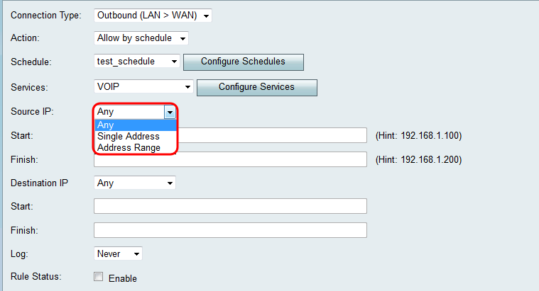
The available options are defined as follows:
• Any — Applies to traffic originating from any IP address in the local network. Therefore, leave the Start and Finish fields blank. Skip to Step 4 if you choose this option.
• Single Address — Applies to traffic originating from a single IP address in the local network. Enter the IP address in the Start field.
• Address Range — Applies to traffic originating from a range of IP addresses in the local network. Enter the starting IP address of the range in the Start field and the ending IP address in the Finish field in order to set the range.
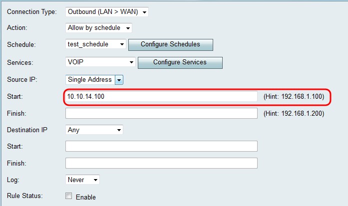
Step 2. If you chose Single Address in Step 1, enter the IP address that will be applied to the access rule in the Start field, and then skip to Step 4. If you chose Address Range in Step 1, enter a starting IP address that will be applied to the access rule in the Start field.
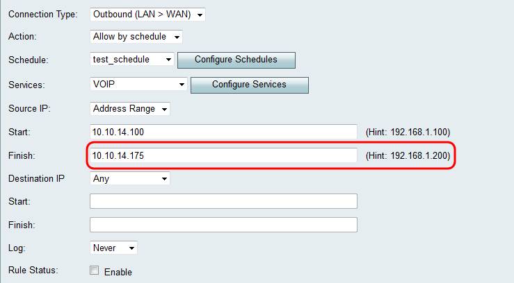
Step 3. If you chose Address Range in Step 1, enter the ending IP address that will encapsulate the IP address range for the access rule in the Finish field.
Step 4. Choose how you would like to define the Destination IP from the Destination IP drop-down list. For outbound traffic, the Destination IP refers to the address or addresses (in the WAN) to which traffic is permitted or denied from the local network.
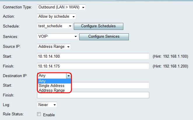
The available options are defined as follows:
• Any — Applies to traffic headed towards any IP address in the public Internet. Therefore, leave the Start and Finish fields blank.
• Single Address — Applies to traffic headed towards a single IP address in the public Internet. Enter the IP address in the Start field.
• Address Range — Applies to traffic headed towards a range of IP addresses in the public Internet. Enter the starting IP address of the range in the Start field and the ending IP address in the Finish field in order to set the range.
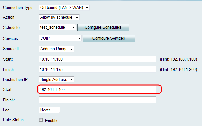
Step 5. If you chose Single Address in Step 4, enter the IP address that will be applied to the access rule in the Start field. If you chose Address Range in Step 4, enter a starting IP address that will be applied to the access rule in the Start field.
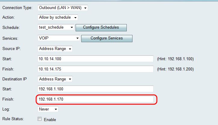
Step 6. If you chose Address Range in Step 4, enter the ending IP Address that will encapsulate the IP Address range for the access rule in the Finish field.
Configuring Source and Destination IP for Inbound traffic
Follow the steps in this section if Inbound (WAN > LAN) or Inbound (WAN > DMZ) was selected as the Connection Type in Step 3 of Adding an Access Rule.
Step 1. Choose how you would like to define the Source IP from the Source IP drop-down list. For inbound traffic, the Source IP refers to the address or addresses (in the WAN) to which the Firewall rule would apply.
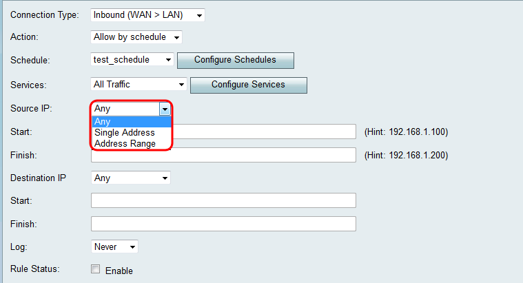
The available options are defined as follows:
• Any — Applies to traffic originating from any IP address in the public Internet. Therefore, leave the Start and Finish fields blank. Skip to Step 4 if you choose this option.
• Single Address — Applies to traffic originating from a single IP address in the public Internet. Enter the IP address in the Start field.
• Address Range — Applies to traffic originating from a range of IP addresses in the public Internet. Enter the starting IP address of the range in the Start field and the ending IP address in the Finish field in order to set the range.
Step 2. If you chose Single Address in Step 1, enter the IP address that will be applied to the access rule in the Start field, and then skip to Step 4. If you chose Address Range in Step 1, enter a starting IP address that will be applied to the access rule in the Start field.
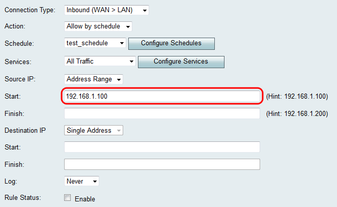
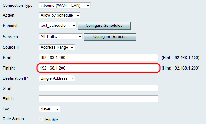
Step 3. If you chose Address Range in Step 1, enter the ending IP address that will encapsulate the IP address range for the access rule in the Finish field.
Step 4. Enter a Single Address for the Destination IP in the Start field below the Destination IP drop-down list. For inbound traffic, the Destination IP refers to the address (in the LAN) to which traffic is permitted or denied from the public Internet.
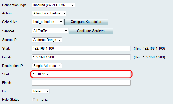
Note: If Inbound (WAN > DMZ) was selected as the Connection Type in Step 3 of Adding an Access Rule, the Single Address for the Destination IP is automatically configured with the IP address of the enabled DMZ host.
Logging and Enabling the Access Rule
Step 1. Select Always in the Log drop-down list if you want the router to create logs whenever a packet matches a rule. Select Never if want logging to never occur when a rule is matched.

Step 2. Check the Enable checkbox to enable the access rule.
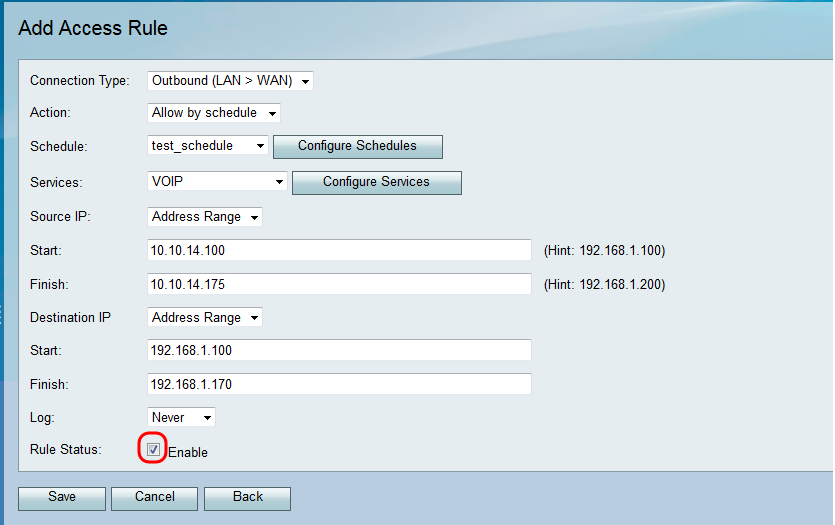
Step 3. Click Save to save your settings.
The Access Rule Table is updated with the newly configured access rule.

Revision History
| Revision | Publish Date | Comments |
|---|---|---|
1.0 |
12-Dec-2018 |
Initial Release |
 Feedback