VLAN Configuration via CLI on CBS250 and CBS350 Series Managed Switches
Available Languages
Objective
VLANs allow you to logically segment a LAN into different broadcast domains. In scenarios where sensitive data may be broadcast on a network, VLANs can be created to enhance security by designating a broadcast to a specific VLAN. Only users that belong to a VLAN are able to access and manipulate the data on that VLAN. VLANs can also be used to enhance performance by reducing the need to send broadcasts and multicasts to unnecessary destinations.
The objective of this document is to show you how to configure a basic VLAN via the Command Line Interface (CLI) on CBS250 and CBS350 Series Managed Switches.
Applicable Devices | Software Version
- CBS250 (Data Sheet) | 3.0.0
- CBS350 (Data Sheet) | 3.0.0
- CBS350-2X (Data Sheet) | 3.0.0
- CBS350-4X (Data Sheet) | 3.0.0
Basic VLAN Configuration
Step 1. Login to the switch’s Command Line Interface (CLI).
Creating a VLAN
Step 1. Enter the following commands to create a VLAN:
| Command | Purpose |
| config | Enter configuration mode. |
| vlan database | Enter VLAN database mode. |
| vlan <ID> | Create a new VLAN with an ID specified. |
| end | Exit from configure mode. |
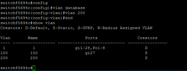
The following screenshot shows the steps required to create a VLAN with an ID of 200.

Step 2. (Optional) Enter the following command to display VLAN information:
| Command | Purpose |
| show vlan | Display VLAN information. |
Note: The VLAN information table will vary depending on the type of switch you are using. For example, SF-type switches may have a Type and Authorization field as opposed to a Creators field. The Ports field will also vary since different switches have different port types and numbering schemes.
The created VLAN is displayed:

Note: VLAN 1 is the default VLAN, which by default, includes all possible ports on the switch. Ports that are numbered with gi are Gigabit Ethernet (individual links). Ports that are numbered with fa are Fast Ethernet (individual links). Ports that are numbered with Po are port-channels (a group of Ethernet links).
Assigning a Port to a VLAN
Once the VLANs are created, you need to assign the ports to the appropriate VLAN. You can configure ports using the switchport command and specify whether the port should be in access or trunk mode.
The port modes are defined as follows:
• Access — frames received on the interface are assumed to not have a VLAN tag and are assigned to the VLAN indicated by the command. Access ports are used primarily for hosts and can only carry traffic for a single VLAN.
• Trunk — frames received on the interface are assumed to have VLAN tags. Trunk ports are for links between switches or other network devices and are capable of carrying traffic for multiple VLANs.
Note: By default, all interfaces are in trunk mode, which means they can carry traffic for all VLANs.
Step 1. Enter the following commands to configure an access port:
| Command | Purpose |
| conf t | Enter configuration mode. |
| int <port number> | Enter interface configuration mode for the specified port number. Gigabit Ethernet, Fast Ethernet and port-channels are valid. |
| switchport mode access | Sets the interface as a nontrunking nontagged single-VLAN Ethernet interface. An access port can carry traffic in one VLAN only. |
| switchport access vlan <ID> | Specifies the VLAN for which this access port will carry traffic. |
| no shut | Turn on (enable) the port. |
| end | Exit from configure mode. |
The following screenshot shows the steps required to configure the Gigabit Ethernet port (gi2) as an access port and assign it to VLAN 200.

Step 2. (Optional) Enter the show vlan command to see your assigned port.

Step 3. Enter the following commands to configure a trunk port and specify that only certain VLANs are allowed on the specified trunk:
| Command | Purpose |
| conf t | Enter configuration mode. |
| int <port number> | Enter interface configuration mode for the specified port number. Gigabit Ethernet, Fast Ethernet and port-channels are valid. |
| switchport mode trunk | Make the specified port number aware of all VLANs. |
| switchport trunk allowed vlan add <ID> | Makes the port a member in the specified VLAN ID and gives it an Egress Rule: Tagged. This means packets are tagged with the VLAN ID as they leave this port on the device. |
| no shut | Turn on (enable) the port. |
| end | Exit from configure mode. |
Note: In trunk mode, all VLANs are allowed by default. Using the switchport trunk allowed vlan add command lets you configure the VLANs allowed on the trunk.
The following screenshot shows the steps required to set the Gigabit Ethernet port (gi3) as a trunk port and add it to VLAN 200:

Step 4. (Optional) Enter the show vlan command to see your changes.

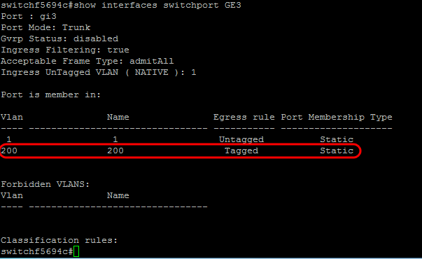
Step 5. (Optional) Enter the following command to display information about a port:
| Command | Purpose |
| show interfaces switchport <port number> | Display information such as VLAN membership, the Egress rule, and forbidden VLANs for the specified port. |
