Configure 802.1x Port Authentication Setting on a Switch
Available Languages
Objective
IEEE 802.1x is a standard which facilitates access control between a client and a server. Before services can be provided to a client by a Local Area Network (LAN) or switch, the client connected to the switch port has to be authenticated by the authentication server which runs Remote Authentication Dial-In User Service (RADIUS).
802.1x authentication restricts unauthorized clients from connecting to a LAN through publicity-accessible ports. 802.1x authentication is a client-server model. In this model, network devices have the following specific roles:
-
Client or supplicant — A client or supplicant is a network device that requests access to the LAN. The client is connected to an authenticator.
-
Authenticator — An authenticator is a network device that provides network services and to which supplicant ports are connected. The following authentication methods are supported:
-
802.1x-based — Supported in all authentication modes. In 802.1x-based authentication, the authenticator extracts the Extensible Authentication Protocol (EAP) messages from the 802.1x messages or EAP over LAN (EAPoL) packets, and passes them to the authentication server, using the RADIUS protocol.
-
MAC-based — Supported in all authentication modes. With Media Access Control (MAC)-based, the authenticator itself executes the EAP client part of the software on behalf of the clients seeking network access.
-
Web-based — Supported only in multi-sessions modes. With web-based authentication, the authenticator itself executes the EAP client part of the software on behalf of the clients seeking network access.
-
Authentication server — An authentication server performs the actual authentication of the client. The authentication server for the device is a RADIUS authentication server with EAP extensions.
Note: A network device can be either a client or supplicant, authenticator, or both per port.
The image below displays a network that have configured the devices according to the specific roles. In this example, an SG350X switch is used.

Guidelines in configuring 802.1x:
-
Create a Virtual Access Network (VLAN). To create VLANs using the web-based utility of your switch, click here. For CLI-based instructions, click here.
-
Configure Port to VLAN settings on your switch. To configure using the web-based utility, click here. To use the CLI, click here.
-
Configure 802.1x properties on the switch. 802.1x should be globally enabled on the switch to enable 802.1x port-based authentication. For instructions, click here.
-
(Optional) Configure Time Range on the switch. To learn how to configure time range settings on your switch, click here.
-
Configure 802.1x Port Authentication. This article provides instructions on how to configure 802.1x port authentication settings on your switch.
To learn how to configure mac-based authentication on a switch, click here.
Applicable Devices
-
Sx300 Series
-
Sx350 Series
-
SG350X Series
-
Sx500 Series
-
Sx550X Series
Software Version
-
1.4.7.06 — Sx300, Sx500
-
2.2.8.04 — Sx350, SG350X, Sx550X
Configure 802.1x Port Authentication Settings on a Switch
Configure RADIUS Client Settings
Step 1. Log in to the web-based utility of your switch then choose Advanced in the Display Mode drop-down list.
Note: The available menu options may vary depending on the device model. In this example, SG550X-24 is used.

Step 2. Navigate to Security > RADIUS Client.

Step 3. Scroll down to the RADIUS Table section and click Add… to add a RADIUS server.

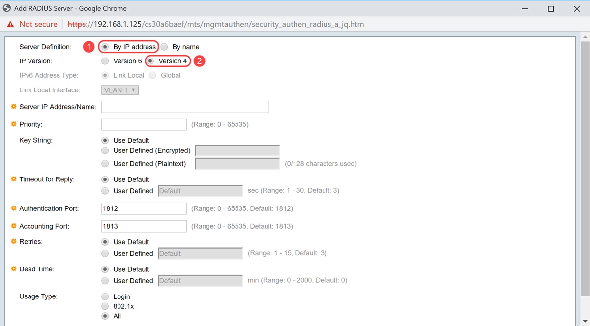
Step 4. Select whether to specify the RADIUS server by IP address or name in the Server Definition field. Select the version of the IP address of the RADIUS server in the IP Version field.
Note: We will be using By IP address and Version 4 in this example.
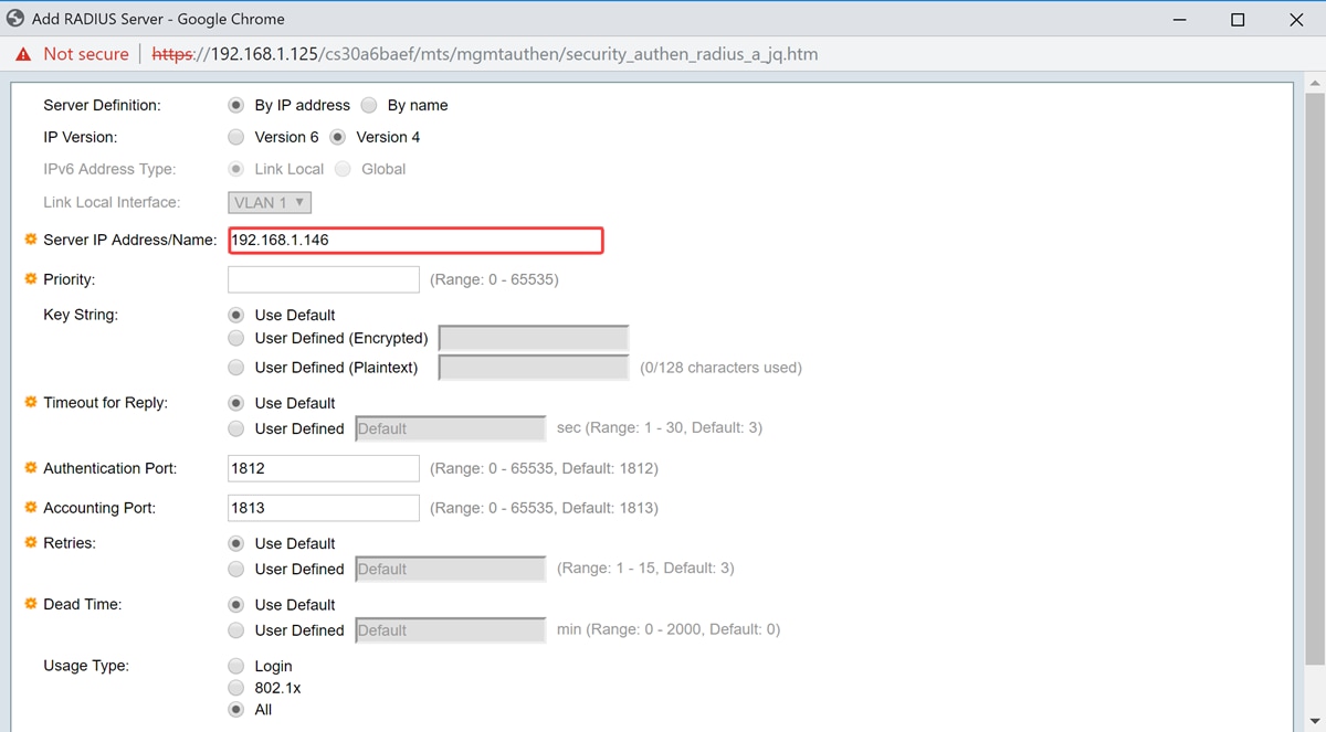
Step 5. Enter in the RADIUS server by IP address or name.
Note: We will be entering the IP address of 192.168.1.146 in the Server IP Address/Name field.
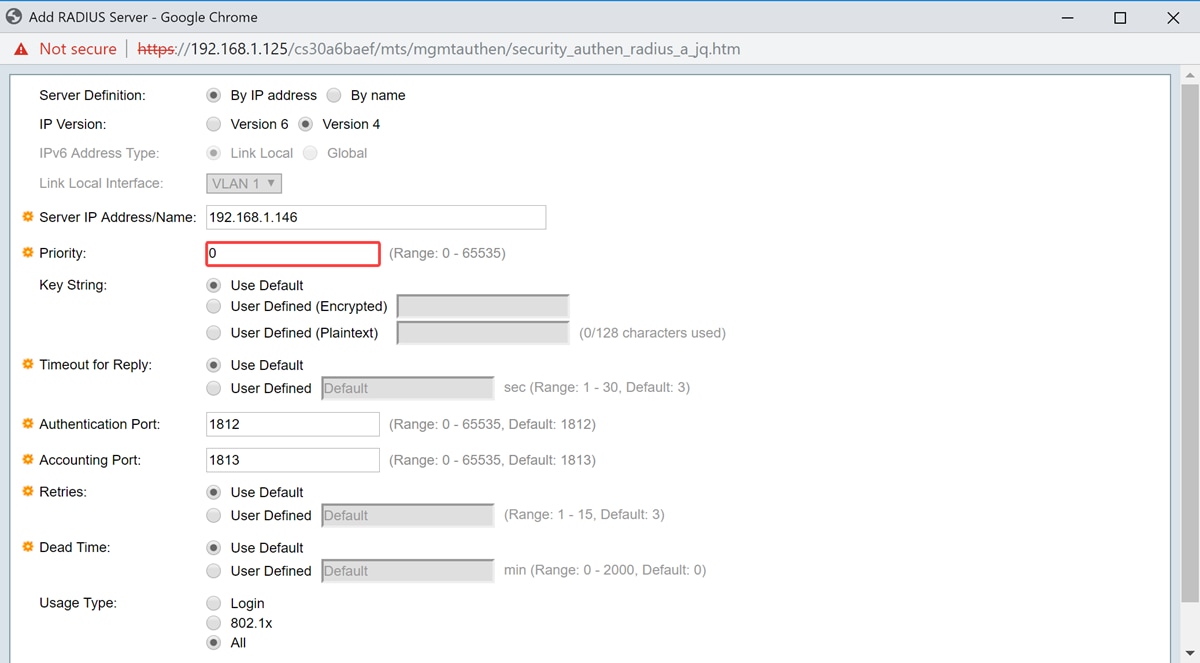
Step 6. Enter the priority of the server. The priority determines the order the device attempts to contact the servers to authenticate a user. The device starts with the highest priority RADIUS server first. 0 is the highest priority.
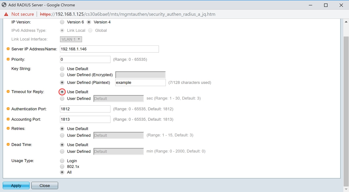
Step 7. Enter the key string used for authenticating and encrypting communication between the device and the RADIUS server. This key must match the key configured on the RADIUS server. It can be entered in Encrypted or Plaintext format. If Use Default is selected, the device attempts to authenticate to the RADIUS server by using the default key string.
Note: We will be using the User Defined (Plaintext) and entering in the key example.
To learn how to configure the RADIUS server settings on your switch, click here.

Step 8. In the Timeout for Reply field, select either Use Default or User Defined. If User Defined was selected, enter the number of seconds the device waits for an answer from the RADIUS server before retrying the query, or switching to the next server if the maximum number of retries made. If Use Default is selected, the device uses the default timeout value.
Note: In this example, Use Default was selected.
Step 9. Enter the UDP port number of the RADIUS server port for authentication request in the Authentication Port field. Enter the UDP port number of the RADIUS server port for accounting requests in the Accounting Port field.
Note: In this example, we will be using the default value for both authentication port and accounting port.
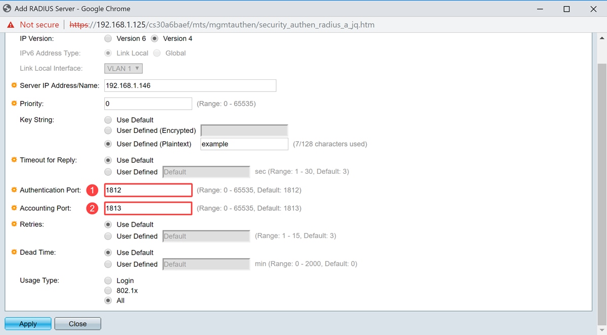
Step 10. If User Defined is selected for Retries field, enter the number of requests that are sent to the RADIUS server before a failure is considered to have occurred. If Use Default was selected, the device uses the default value for the number of retries.
If User Defined is selected for Dead Time, enter the number of minutes that must pass before a non-responsive RADIUS server is bypassed for service requests. If Use Default was selected, the device uses the default value for the dead time. If you entered 0 minutes, there is no dead time.
Note: In this example, we will be selecting Use Default for both of these fields.

Step 11. In the Usage Type field, enter the RADIUS server authentication type. The options are:
-
Login – RADIUS server is used for authenticating users that ask to administer the device.
-
802.1x – RADIUS server is used for 802.1x authentication.
-
All – RADIUS server is used for authenticating user that ask to administer the device and for 802.1x authentication.

Step 12. Click Apply.

Configure 802.1x Port Authentication Settings
Step 1. Log in to the web-based utility of your switch then choose Advanced in the Display Mode drop-down list.
Note: The available menu options may vary depending on the device model. In this example, SG350X-48MP is used.

Note: If you have an Sx300 or Sx500 Series switch, skip to Step 2.
Step 2. Choose Security > 802.1X Authentication > Port Authentication.

Step 3. Choose an interface from the Interface Type drop-down list.
-
Port — From the Interface Type drop-down list, choose Port if only a single port needs to be chosen.
-
LAG — From the Interface Type drop down list, choose the LAG to configure. This affects the group of ports defined in the LAG configuration.
Note: In this example, Port of Unit 1 is chosen.

Note: If you have a non-stackable switch such as a Sx300 Series switch, skip to Step 5.
Step 4. Click Go to bring up a list of ports or LAGs on the interface.

Step 5. Click the port that you want to configure.

Note: In this example, GE4 is chosen.
Step 6. Scroll down the page then click Edit.

Step 7. (Optional) If you want to edit another interface, choose from the Unit and Port drop-down lists.

Note: In this example, port GE4 of unit 1 is chosen.
Step 8. Click the radio button that corresponds to the desired port control in the Administrative Port Control area. The options are:
-
Force Unauthorized — Denies the interface access by moving the port into the unauthorized state. The port will discard traffic.
-
Auto — The port moves between an authorized or unauthorized state based on authentication of the supplicant.
-
Force Authorized — Authorizes the port without authentication. The port will forward traffic.

Note: In this example, Auto is chosen.
Step 9. Click a RADIUS VLAN Assignment radio button to configure dynamic VLAN assignment on the selected port. The options are:
-
Disable — Feature is not enabled.
-
Reject — If the RADIUS server authorized the supplicant, but did not provide a supplicant VLAN, the supplicant is rejected.
-
Static — If the RADIUS server authorized the supplicant, but did not provide a supplicant VLAN, the supplicant is accepted.

Note: In this example, Static is chosen.
Step 10. Check Enable in the Guest VLAN check box to enable Guest VLAN for unauthorized ports. Guest VLAN makes the unauthorized port automatically join the VLAN chosen in the Guest VLAN ID area of the 802.1 properties.

Step 11. (Optional) Check the Enable Open Access check box to enable open access. Open Access helps you to understand the configuration problems of hosts connecting to the network, monitors bad situations and enables these problems to be fixed.
Note: When Open Access is enabled on an interface, the switch treats all failures received from a RADIUS server as successes and allows access to the network for stations connected to interfaces regardless of authentication results. In this example, Open Access is disabled.

Step 12. Check the Enable 802.1x Based Authentication check box to enable 802.1X authentication on the port.

Step 13. Check the Enable MAC Based Authentication check box to enable port authentication based on the supplicant MAC address. Only eight MAC-based authentications can be used on the port.
Note: For MAC authentication to succeed, the RADIUS server supplicant username and password must be the supplicant MAC address. The MAC address must be in lower case letters and entered without the . or – separators (such as 0020aa00bbcc).

Note: In this example, MAC-based authentication is disabled.
Step 14. Check the Enable Web Based Authentication check box to enable web-based authentication on the switch. In this example, web-based authentication is disabled.

Note: In this example, web-based authentication is disabled.
Step 15. (Optional) Check the Enable Periodic Reauthentication check box to force the port to re-authenticate after a given time. This time is defined in the Reauthentication Period field.

Note: In this example, period re-authentication is enabled.
Step 16. (Optional) Enter a value in the Reauthentication Period field. This value represents the amount of seconds before the interface re-authenticates the port. The default value is 3600 seconds and the range is from 300 to 4294967295 seconds.

Note: In this example, 6000 seconds is configured.
Step 17. (Optional) Check the Enable Reauthenticate Now check box to force an immediate port re-authentication. In this example, immediate re-authentication is disabled.

The Authenticator State area displays the authorization state of the port.
Step 18. (Optional) Check the Enable Time Range check box to enable a limit on the time that the port is authorized.

Note: In this example, Time Range is enabled. If you prefer to skip this feature, proceed to Step 20.
Step 19. (Optional) From the Time Range Name drop-down list, choose a time range to use.

Note: In this example, Dayshift is chosen.
Step 20. In the Maximum WBA Login Attempts area, click either Infinite for no limit or User Defined to set a limit. If User Defined is chosen, enter the maximum number of login attempts allowed for web-based authentication.

Note: In this example, Infinite is chosen.
Step 21. In the Maximum WBA Silence Period area, click either Infinite for no limit or User Defined to set a limit. If User Defined is chosen, enter the maximum length of the silent period for web-based authentication allowed on the interface.

Note: In this example, Infinite is chosen.
Step 22. In the Max Hosts area, click either Infinite for no limit or User Defined to set a limit. If User Defined is chosen, enter the maximum number of authorized hosts allowed on the interface.

Note: Set this value to 1 to simulate single-host mode for web-based authentication in multi-sessions mode. In this example, Infinite is chosen.
Step 23. In the Quiet Period field, enter the time the switch remains in quiet state after a failed authentication exchange. When the switch is in quiet state, it means the switch is not listening for new authentication requests from the client. The default value is 60 seconds and the range is from one to 65535 seconds.

Note: In this example, the quiet period is set to 120 seconds.
Step 24. In the Resending EAP field, enter the time the switch waits for a response message from the supplicant before resending a request. The default value is 30 seconds and the range is from one to 65535 seconds.

Note: In this example, resending EAP is set to 60 seconds.
Step 25. In the Max EAP Requests field, enter the maximum number of EAP requests that can be sent. EAP is an authentication method used in 802.1X that provides authentication information exchange between the switch and the client. In this case, EAP requests are sent to the client for authentication. The client then has to respond and match the authentication information. If the client does not respond, then another EAP request is set based on the Resending EAP value and the authentication process is restarted. The default value is 2 and the range is from one to 10.

Note: In this example, the default value of 2 is used.
Step 26. In the Supplicant Timeout field, enter the time before EAP requests are resent to the supplicant. The default value is 30 seconds and the range is from one to 65535 seconds.

Note: In this example, supplicant timeout is set to 60 seconds.
Step 27. In the Server Timeout field, enter the time that elapses before the switch sends a request again to the RADIUS server. The default value is 30 seconds and the range is from one to 65535 seconds.

Note: In this example, server timeout is set to 60 seconds.
Step 28. Click Apply then click Close.

Step 29. (Optional) Click Save to save settings to the startup configuration file.
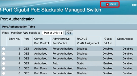
You should now have successfully configured the 802.1x port authentication settings on your switch.
Apply Interface Configuration Settings to Multiple Interfaces
Step 1. Click the radio button of the interface that you want to apply the authentication configuration to multiple interfaces.
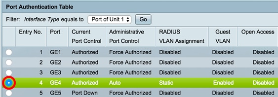
Note: In this example, GE4 is chosen.
Step 2. Scroll down then click Copy Settings.

Step 3. In the to field, enter the range of interfaces that you want to apply the configuration of the chosen interface. You can use the interface numbers or the name of the interfaces as input. You can enter each interface separated by a comma (such as 1, 3, 5 or GE1, GE3, GE5) or you can enter a range of interfaces (such as 1-5 or GE1-GE5).

Note: In this example, the configuration settings will be applied to ports 47 to 48.
Step 4. Click Apply then click Close.

The image below depicts the changes after the configuration.

You should now have successfully copied the 802.1x authentication settings of one port and applied to other port or ports on your switch.
Revision History
| Revision | Publish Date | Comments |
|---|---|---|
1.0 |
11-Dec-2018 |
Initial Release |
 Feedback