Configure MAC-Based Access Control List (ACL) and Access Control Entry (ACE) on a Managed Switch
Available Languages
Objective
An Access Control List (ACL) is a list of network traffic filters and correlated actions used to improve security. It blocks or allows users to access specific resources. An ACL contains the hosts that are permitted or denied access to the network device. Media Access Control (MAC)-based Access Control List (ACL) is a list of source MAC addresses that use Layer 2 information to permit or deny access to traffic. If a packet is coming from a wireless access point to a Local Area Network (LAN) port or vice versa, this device will check if the source MAC address of the packet matches any entry in this list and checks the ACL rules against the content of the frame. It then uses the matched results to permit or deny this packet. However, packets from LAN to LAN port will not be checked. An Access Control Entry (ACE) contains the actual access rule criteria. Once the ACE is created, it is applied to an ACL. You should use access lists to provide a basic level of security for accessing your network. If you do not configure access lists on your network devices, all packets passing through the switch or router could be allowed onto all parts of your network.
This article provides instructions on how to configure MAC-based ACL and ACE on your Managed Switch.
Applicable Devices | Software Version
- Sx350 Series | 2.2.0.66 (Download latest)
- SG350X Series | 2.2.0.66 (Download latest)
- Sx500 Series | 1.4.5.02 (Download latest)
- Sx550X Series | 2.2.0.66 (Download latest)
Configure MAC-Based ACL and ACE
Configure MAC-Based ACL
Step 1. Log in to the web-based utility then go to Access Control > MAC-Based ACL.
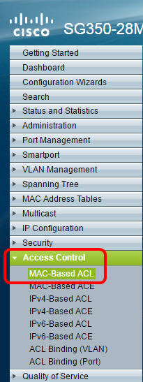
Step 2. Click the Add button.
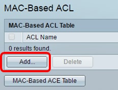
Step 3. Enter the name of the new ACL in the ACL Name field.

Step 4. Click Apply then click Close.

Step 5. (Optional) Click Save to save settings in the startup configuration file.
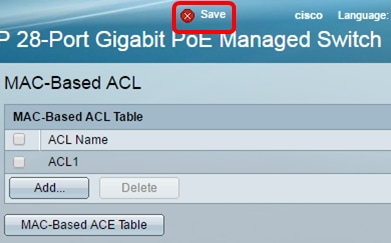
You should now have configured a MAC-based ACL on your switch.
Configure MAC-Based ACE
When a frame is received on a port, the switch processes the frame through the first ACL. If the frame matches an ACE filter of the first ACL, the ACE action takes place. If the frame matches none of the ACE filters, the next ACL is processed. If no match is found to any ACE in all relevant ACLs, the frame is dropped by default.
In this scenario, an ACE will be created to deny traffic that is sent from a specific user-defined source MAC address to any destination addresses.
Note: This default action can be avoided by the creation of a low priority ACE that permits all traffic.
Step 1. On the web-based utility, go to Access Control > MAC-Based ACE.
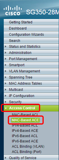
Important: To fully utilize the available features and functions of the switch, change to Advanced mode by choosing Advanced from the Display Mode drop-down list in the upper-right corner of the page.

Step 2. Choose an ACL from the ACL Name drop-down list then click Go.
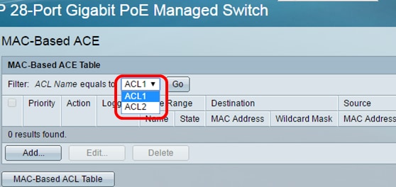
Note: The ACEs that are already configured for the ACL will be displayed in the table.
Step 3. Click the Add button to add a new rule to the ACL.
Note: The ACL Name field displays the name of the ACL.
Step 4. Enter the priority value for the ACE in the Priority field. ACEs with a higher priority value are processed first. The value 1 is the highest priority.

Step 5. (Optional) Check the Enable Logging check box to enable logging ACL flows that match the ACL rule.
Step 6. Click the radio button that corresponds to the desired action that is taken when a frame meets the required criteria of the ACE.
Note: In this example, Deny is chosen.

-
Permit — The switch forwards packets that meet the required criteria of the ACE.
-
Deny — The switch drops packets that meet the required criteria of the ACE.
-
Shutdown — The switch drops packets that do not meet the required criteria of the ACE and disables the port where the packets were received.
Note: Disabled ports can be reactivated on the Port Settings page.
Step 7. (Optional) Check the Enable Time Range check box to allow a time range to be configured to the ACE. Time ranges are used to limit the amount of time an ACE is in effect.

Step 8. (Optional) From the Time Range Name drop-down list, choose a time range to apply to the ACE.

Note: You can click Edit to navigate to and create a time range on the Time Range page.

Step 9. Click the radio button that corresponds to the desired criteria of the ACE in the Destination MAC Address area.

The options are:
-
Any — All destination MAC addresses apply to the ACE.
-
User Defined — Enter a MAC address and MAC wildcard mask that are to be applied to the ACE in the Destination MAC Address Value and Destination MAC Wildcard Mask fields. Wildcard masks are used to define a range of MAC addresses.
Note: In this example, Any is chosen. Choosing this option means that the ACE to be created will deny the ACE traffic.
Step 10. Click the radio button that corresponds to the desired criteria of the ACE in the Source MAC Address area.
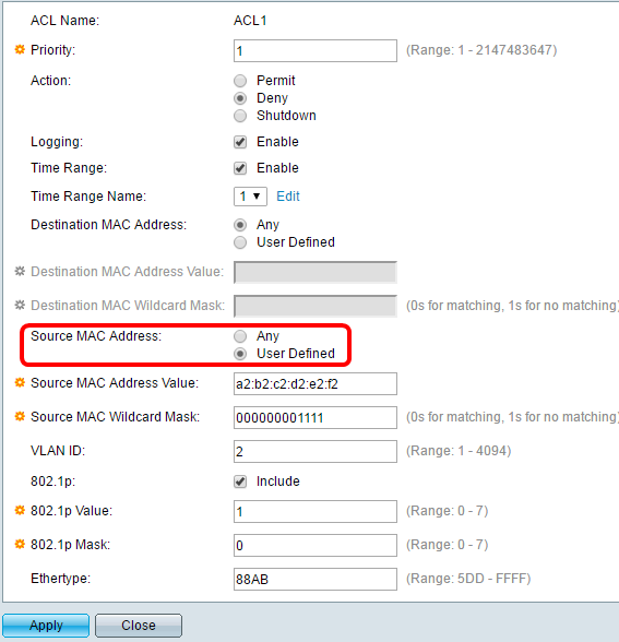
The options are:
-
Any — All source MAC addresses apply to the ACE.
-
User Defined — Enter a MAC address and MAC wildcard mask that are to be applied to the ACE in the Source MAC Address Value and Source MAC Wildcard Mask fields. Wildcard masks are used to define a range of MAC addresses.
Note: In this example, User Defined is chosen.
Step 11. (Optional) In the VLAN ID field, enter a VLAN ID that will be matched with the VLAN tag of the frame.
Step 12. (Optional) To Include 802.1p values in ACE Criteria, check Include in the 802.1p check box. The 802.1p involves the technology Class of Service (CoS). CoS is a 3-bit field in an Ethernet frame that is used to differentiate traffic.
Step 13. If 802.1p values are included, enter the following fields:
-
802.1p Value — Enter the 802.1p value that is to be matched. The 802.1p is a specification that gives Layer 2 switches the ability to prioritize traffic and to perform dynamic multicast filtering. The values are as follows:
– 0 — Background. The data that is least prioritized like bulk transfers, games, and so on.
– 1 — Best Effort. The data which needs best-effort delivery on ordinary LAN priority. The network does not provide any guarantee on delivery, but the data obtains unspecified bit rate and delivery time based upon the traffic.
– 2 — Excellent Effort. The data that needs best effort delivery for important users.
– 3 — Critical Application like Linux Virtual Server (LVS) phone Session Initiation Protocol (SIP).
– 4 — Video. Latency and Jitter less than 100 ms.
– 5 — Voice Cisco IP phone default. Latency and Jitter less than 10 ms.
– 6 — Inter-network Control LVS phone Real-time Transport Protocol (RTP).
– 7 — Network Control. High requirement to get through to maintain and support the network infrastructure.
-
802.1p Mask — Enter the wildcard mask of the 802.1p values. This wildcard mask is used to define the range of 802.1p values.
Step 14. (Optional) Enter the Ethertype of the frame that is to be matched. Ethertype is a 2-octet field in an Ethernet frame that is used to indicate which protocol is utilized for the payload of the frame.
Step 14. Click Apply then click Close. The ACE is created and associated to the ACL name.
Step 15. Click Save to save settings to the startup configuration file.
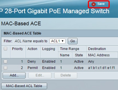
You should now have configured a MAC-based ACE on your switch.
Other links you might find valuable: