Configure VLAN Interface IPv4 Address on an Sx350 or SG350X Switch
Available Languages
Objective
This article provides instructions on how to configure VLAN interface IPv4 address on the switch.
Introduction
The switch can have multiple IP addresses and can be configured either on a port, a Link Aggregation Group (LAG), a Virtual Local Area Network (VLAN), or a loopback interface. If a switch does not have a Dynamic Host Configuration Protocol (DHCP) server then the IP address needs to be assigned statically. The switch routes traffic between the directly-attached IP subnets configured on the device and continues to bridge traffic between devices in the same VLAN. Traffic is routed by the device in layer 3 mode.
If you are unfamiliar with the terms used below, check out Cisco Business: Glossary of New Terms.
Note: For instructions on how to configure IPv4 management interfaces on the switch, click here.
Applicable Devices
- Sx350 Series
- SG350X Series
Software Version
- 2.3.0.130
Configure IPv4 Management Interface
When the switch is in a stacking mode with a standby switch present, it is recommended to configure the IP address as a static address to prevent disconnecting from the network during a stacking active switchover. This is because when the standby switch takes control of the stack, when using DHCP, it might receive a different IP address than the one that was received by the original active-enabled unit on the stack.
Enable IPv4 Routing
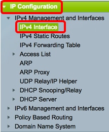
Step 1. Log in to the web-based utility of the switch then choose IP Configuration >IPv4 Management and Interfaces > IPv4 Interface.
Note: The available menu options may vary depending on the device model. In this example, SG350X-48MP is used.
Step 2. To enable IPv4 routing, check the Enable IPv4 Routing check box.
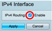
Note: If you want to configure VLAN mapping on your switch, you must disable this feature.
Step 3. Click Apply.
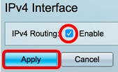
You should now have successfully enabled IPv4 routing on your switch.
Configure IPv4 Address on the Interface
The IPv4 Interface Table on the IPv4 Interface page contains the following information:
- Interface - The Unit or interface for which the IP address is defined. This can also be a loopback interface.
- IP Address Type - The available options are:
- DHCP - Received from Dynamic Host Configuration Protocol (DHCP) server.
- Static - Entered manually. Static interfaces are non-DHCP interfaces that are created by the user.
- Default - The default address that exists on the device by default, before any configurations have been made.
- IP Address - Configured IP address for the interface.
- Mask - Configured IP address mask.
- Status - Results of the IP address duplication check.
- Tentative - There is no final result for the IP address duplication check.
- Valid - The IP address collision check was completed, and no IP address collision was detected.
- Valid-Duplicated - The IP address duplication check was completed, and a duplicate IP address was detected.
- Duplicated - A duplicated IP address was detected for the default IP address.
- Delayed - The assignment of the IP address is delayed for 60 seconds if DHCP Client is enabled on startup in order to give time to discover DHCP address.
- Not Received - Relevant only for DHCP Address. When a DCHP Client starts a discovery process, it assigns a dummy IP address 0.0.0.0 before the real address is obtained. This dummy address has the status of Not Received.
Note: In this example, the IPv4 Interface Table contains the default VLAN 1 which has a DHCP-assigned IP address of 192.168.100.19 with 255.255.255.224 subnet mask.
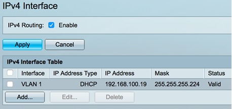
Step 1. To add a new interface, click the Add button.

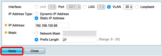
Step 2. In the Interface area, click on the radio button of the interface type that you want to assign with an IP address then choose the specific interface accordingly.

Note: In this example, VLAN is clicked and VLAN 20 is chosen from the drop-down list. To learn how to configure VLANs on your switch, click here.
Step 3. In the IP Address Type area, choose from the following options:
- Dynamic IP Address - The IP address is received from DHCP server. If this option is chosen, skip to Step 6.
- Static IP Address - The IP address is entered manually. Static interfaces are non-DHCP interfaces that are created by the user.

Note: In this example, Static IP Address is chosen.
Step 4. (Optional) If Static IP Address is chosen, enter the IP address in the IP Address field.

Note: In this example 192.168.100.66 is used.
Step 5. Click a radio button from the Mask area then enter the corresponding subnet mask. The options are:
- Network Mask - IP mask for this address.
- Prefix Length - Length of the IPv4 prefix.

Note: In this example, Prefix Length is chosen and 27 is entered in the corresponding field which also translates to 255.255.255.224 network mask.
Step 6. Click Apply then click Close.
Step 7. (Optional) Click Save to save settings to the startup configuration file.
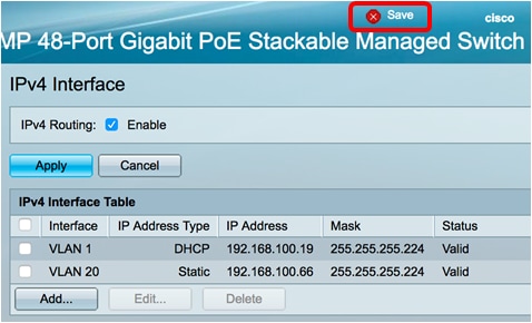
You have now successfully configured the IPv4 management interface settings on your switch through the web-based utility.
Edit or Delete an IPv4 Management Interface
Step 1. To edit the interface, check the check box of the entry that you want to modify then click the Edit button.

Note: In this example, VLAN 20 will be edited.
Step 2. Update the necessary details on the page then click Apply then Close.
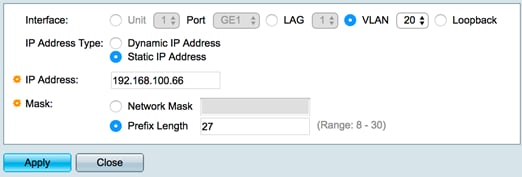
Step 3. To delete an interface, check the check box of the entry that you want to modify then click the Delete button.

Note: In this example, VLAN 20 will be deleted.
The page will update indicating that you have deleted the interface.
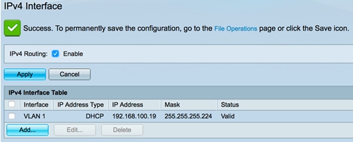
You should now have successfully edited or deleted an IPv4 management interface on your switch through the web-based utility.
Access the IPv4 Management Interface
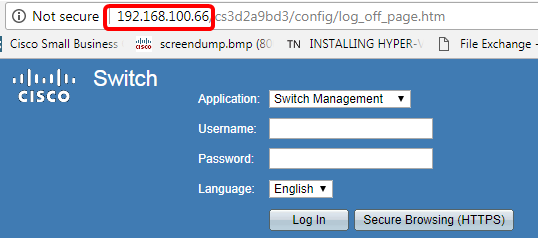
Step 1. To access the web-based utility of the interface, enter the IP address on your web browser.
Note: Make sure that your computer is connected on the same VLAN as the switch interface. In this example, 192.168.100.66 is entered.
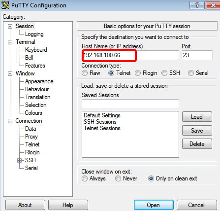
Step 2. (Optional) To access the CLI of the switch interface, enter the IP address in the client that you are using. In this example, PuTTY is used.
Note: To learn how to access an SMB switch CLI through SSH or Telnet, click here.
The CLI of the switch should be accessible.
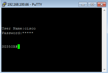
You have now successfully accessed the CLI or the web-based utility of the switch using IPv4 management interface IP address.
Note: To learn how to configure additional IPv4 routes for routing to non-directly attached subnets on the switch, click here.
Revision History
| Revision | Publish Date | Comments |
|---|---|---|
1.0 |
13-Dec-2018 |
Initial Release |
 Feedback